Victaulic Vic-Flex AH1 Series Manual
Sprinkler fittings, braided flexible hose
Hide thumbs
Also See for Vic-Flex AH1 Series:
- Installation instructions manual (20 pages) ,
- Field installation handbook (204 pages)
Table of Contents
Advertisement
Quick Links
Victaulic
Vic-Flex™ Sprinkler Fittings
®
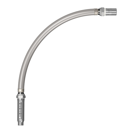
Series AH1 Braided Flexible Hose
1.0 PRODUCT DESCRIPTION
Available Sizes by Component
• Series AH1 Braided Hose: 31, 36, 48, 60, 72"/790, 914, 1220, 1525, 1830 mm. Note: length includes adapter
nipple and 5.75"/140 mm straight reducer.
• Sprinkler Reducers: ½" and ¾"/15 and 20 mm sprinkler connections and 5.75"/140 mm, 9"/230 mm, 13"/330 mm
straight lengths and short, long 90º elbows. Note: The short 90° elbow is typically used with concealed sprinklers
while the long 90º elbow is typically used in the installation of recessed pendent sprinklers.
• Adapter Nipples: 1"/25 mm NPT or BSPT adapter nipples for attaching to pipe and fittings outlined in NFPA
standards. ¾"/20 mm NPT or BSPT available for VdS. 1 ¼"/ 32mm BSPT available for LPCB.
• Brackets:
• Style AB1 for suspended and hard-lid ceilings, allows installation before ceiling tiles in place
• Style AB2 for suspended and hard-lid ceilings, allows for vertical sprinkler adjustment, and installation before
ceiling tiles in place
• Style AB3 for surface mount applications, wood, metal and block walls
• Style AB4 for hard-lid ceilings with hat furring channel grid systems, allows for vertical sprinkler adjustment
• Style AB6 for cold storage applications, refer to submittal 10.90
• Style AB7 for suspended and hard-lid ceilings
• Style AB7 Adjustable for suspended and hard-lid ceilings
• Style AB8 for hard-lid ceilings with CD 60/27 profile metal studs (regionally available)
• Style AB9 for hard-lid ceilings with hat furring channel grid systems
• Style AB10 for Armstrong
Maximum Working Temperature
• 225°F/107°C
Maximum Working Pressure
• 200 psi/1375 kPa (FM Approval)
• 175 psi/1206 kPa (cULus Listed)
• 1600 kPa/232 psi (VdS/LPCB Approved)
ALWAYS REFER TO ANY NOTIFICATIONS AT THE END OF THIS DOCUMENT REGARDING PRODUCT INSTALLATION, MAINTENANCE OR SUPPORT.
System No.
Submitted By
victaulic.com
10.95 8507 Rev A Updated 11/2015
®
TechZone
™
ceilings
Location
Date
© 2015 Victaulic Company. All rights reserved.
Spec Section
Approved
1
10.95
Paragraph
Date
Advertisement
Table of Contents

Subscribe to Our Youtube Channel
Related Manuals for Victaulic Vic-Flex AH1 Series


Summary of Contents for Victaulic Vic-Flex AH1 Series
- Page 1 ALWAYS REFER TO ANY NOTIFICATIONS AT THE END OF THIS DOCUMENT REGARDING PRODUCT INSTALLATION, MAINTENANCE OR SUPPORT. System No. Location Spec Section Paragraph Submitted By Date Approved Date victaulic.com 10.95 8507 Rev A Updated 11/2015 © 2015 Victaulic Company. All rights reserved.
- Page 2 • Gasket Seal: Victaulic EPDM • Isolation Ring: Nylon • Nut and Nipple: Carbon Steel, Zinc Plated • Reducer (½ or ¾"): Carbon Steel, Zinc-Plated Brackets: Carbon Steel, Zinc-Plated 10.95 8507 Rev A Updated 11/2015 © 2015 Victaulic Company. All rights reserved. victaulic.com...
- Page 3 The Short 90° elbow reducer is typically used with concealed sprinklers while the longer 90 elbow is typically used in the installation of recessed pendent sprinklers. 10.95 8507 Rev A Updated 11/2015 © 2015 Victaulic Company. All rights reserved. victaulic.com...
- Page 4 24"/610 mm or 48"/1220 mm Square Bar* Patent-Pending adjustable Center bracket End Bracket Both sizes FM/VdS/LPCB approved, cULus listed Style AB3 • Surface Mount Applications • FM Approved 10.95 8507 Rev A Updated 11/2015 © 2015 Victaulic Company. All rights reserved. victaulic.com...
- Page 5 • Suspended Ceilings • Hard-Lid Ceilings Item Description 700 mm or 1400 mm Square Bar* Patented 1-Bee2® Center Bracket End Bracket (adjustable) Both sizes FM/VdS approved. 10.95 8507 Rev A Updated 11/2015 © 2015 Victaulic Company. All rights reserved. victaulic.com...
- Page 6 Style AB10 • Suspended ceilings • Armstrong ® TechZone ™ Item Description 6"/152 mm Square Bar* Patented 1-Bee2® Center Bracket End Bracket FM/VdS approved, cULus listed. 10.95 8507 Rev A Updated 11/2015 © 2015 Victaulic Company. All rights reserved. victaulic.com...
- Page 7 V2707 ¾" /19 mm MAX. RECESS V2707 MAX. EXTENSION V2707 ¾"/19mm Max. Recess V3802 ½"/12.7mm Max. Recess Hose Clearance Chart Hose Clearance Chart Dimension Dimension inches inches Min. Min. 10.95 8507 Rev A Updated 11/2015 © 2015 Victaulic Company. All rights reserved. victaulic.com...
- Page 8 V2707 ¾"/19 mm MAX. RECESS V2707 MAX. EXTENSION V3802 ½"/12.7mm Max. Recess V2707 ¾"/19mm Max. Recess Hose Clearance Chart Hose Clearance Chart Dimension Dimension inches inches 3.63 Min. Min. 10.95 8507 Rev A Updated 11/2015 © 2015 Victaulic Company. All rights reserved. victaulic.com...
- Page 9 Hose Clearance Chart Hose Clearance Chart Dimension Dimension inches inches inches inches inches inches inches Minimum 3.63 Min. Bend Radius 6.13 7.13 8.13 9.13 10.13 11.13 Min. 10.95 8507 Rev A Updated 11/2015 © 2015 Victaulic Company. All rights reserved. victaulic.com...
- Page 10 Min. Min. NOTE • Variations of ceiling grids, sprinkler heads, brackets, and hoses are permitted but may result in clearance differences from the figures above. 10.95 8507 Rev A Updated 11/2015 © 2015 Victaulic Company. All rights reserved. victaulic.com...
- Page 11 Variations of ceiling grids, sprinkler heads, brackets, and hoses are permitted but may result in clearance differences from the figures above. • See installation instructions for mounting screw type and size. 10.95 8507 Rev A Updated 11/2015 © 2015 Victaulic Company. All rights reserved. victaulic.com...
- Page 12 The system hydraulics can be recalculated using actual equivalent lengths to verify the performance of the system. 10.95 8507 Rev A Updated 11/2015 © 2015 Victaulic Company. All rights reserved. victaulic.com...
- Page 13 EXAMPLE: A 48-inch hose installed with two 30° bends and two 90° bends at a 7-inch bend radius is permitted and considered equivalent to the data in the table shown above. In this example, the total number of degrees is 240°, which is less than the allowable 270°. 10.95 8507 Rev A Updated 11/2015 © 2015 Victaulic Company. All rights reserved. victaulic.com...
- Page 14 20 mm/¾"/90º Elbow 15mm/½"/Straight 15mm/½"/90º Elbow 1525/60 24.0/78.8 1525/60 24.5/80.2 20 mm/¾"/Straight 20 mm/¾"/90º Elbow 15mm/½"/Straight 15mm/½"/90º Elbow 1830/72 28.5/93.4 1830/72 27.8/91.1 20 mm/¾"/Straight 20 mm/¾"/90º Elbow 10.95 8507 Rev A Updated 11/2015 © 2015 Victaulic Company. All rights reserved. victaulic.com...
- Page 15 Warranty under any patent or other intellectual property right of Victaulic or any of its subsidaries Refer to the Warranty section of the current Price List or contact Victaulic for details.
-
Page 16: Material List
www.nibco.com A H E A D O F T H E F L O W ® Revision 11/14/2014 175 PSI WWP Bronze Angle Valves Dezincification Resistant Fire Protection Valve • Screw-in Bonnet • integral Seat • renewable disc 175 PSI/12 .1 Bar Non-Shock Cold Water COnFOrMS tO MSS SP-80 •... - Page 17 Backflow Direct Tamper Switch Recommendation READ INSTRUCTIONS IN FULL BEFORE INSTALLATION. QUESTIONS? CALL 916-760-4524 M-F 8:00 AM – 4:30 PM PST At Backflow Direct we are committed to making our products as easy to install as possible. We design for most contingencies, but installation may be different based on your regional regulations or system design.
- Page 18 Backflow Direct Tamper Switch Recommendation Tools Required: This list is the recommended tools for ease of installation. Other versions of the same tool can be used. For example, Allen Wrenches instead of Allen Drive Sockets. Backflow Direct recommends using a weather proof rigid ½” 90 degree pull elbow, a weather proof rigid ½” LB Conduit Important Note: Body and ½”...
- Page 19 Backflow Direct Tamper Switch Recommendation Install 90 Degree Pull Elbow A. If the pull elbow did not come with a threaded end attach a ½” close nipple to the 90 degree pull elbow. B. run the electrical leads from the gearbox through the 90 degree pull elbow and then attach the 90 degree pull elbow by inserting the close nipple into the threaded port on the gearbox.
- Page 20 Backflow Direct Tamper Switch Recommendation Install LB Conduit Body D. Attach the second ½” close nipple to LB Conduit body to the threaded port that is located at the 90 degree angle. E. Attach the LB Conduit body to 90 degree pull elbow and run electrical leads through the close nipple into the LB Conduit body.
- Page 21 www.nibco.com A H E A D O F T H E F L O W ® Revision 8/3/2010 300 PSI WWP Bronze Ball Valves Dezincification Resistant 300 PSI/20.7 Bar Non-Shock Cold Water MATERIAL LIST PART SPECIFICATION KT-585-70-UL ¹⁄₄ Threaded KT-580-70-UL 1¹⁄₄...
-
Page 22: Data Sheet
data sheet BEAM CLAMPS FILE EX 6559 Malleable Iron • Size Range: 3/8”, 1/2” and 5/8” and rod sizes • Surface Finish: Black, Electro-zinc plated • Structural attachment to top or bottom of metal beams, purlins, channel, or angle iron •... - Page 23 FIG. AN7722-3 A Grooved End Butterfly Valve The Gruvlok Figure AN7722-3A Grooved End Butterfly Valve is ® UL Listed and FM Approved as a system control valve. The valve is rated at 300 psi for steel pipe in the 2” to 10” sizes. The 2” through 10”...
- Page 24 FIG. AN7722-3 A Grooved End Butterfly Valve CLOSED O.D. (MAX) FIGURE AN7722-3A UL/ULC/FM BUTTERFLY VALVE Valve Dimensions Valve Pipe Approx. Size O.D. Wt. Ea. In./DN(mm) In./mm In./mm In./mm In./mm In./mm In./mm In./mm In./mm In./mm In./mm Lbs./Kg 2.375 3.19 2.97 3.87 6.17 4.18 2.25...
-
Page 25: Actuator Wiring
FIG. AN7722-3 A Grooved End Butterfly Valve ACTUATOR WIRING SUPERVISORY SWITCH FIRE ALARM CONTROL PANEL Orange (Common) SUPERVISORY CIRCUIT Yellow Yellow Orange Yellow Common Normally Open (NO): Not Wired Orange Normally Closed (NC): (2) Yellow Common: (2) Orange TO END-OF-LINE RESISTOR OR NEXT SUPERVISORY SWITCH Notes: 1. -
Page 28: Material Specifications
DUCTILE IRON THREADED FITTINGS FIG. 3201 90˚ Elbow For Listings/Approval Details and Limitations, visit our website at www.anvilintl.com or contact an Anvil ® Sales Representative. MATERIAL SPECIFICATIONS FIGURE 3201 - 90° ELBOW Maximum Nominal Size Dimension A Approx. Wt. Each Dimensions: ASME B16.3 Working Pressure Material:... - Page 29 DUCTILE IRON THREADED FITTINGS FIG. 3283 Bushings Inside Head Inside Head For Listings/Approval Details and Limitations, visit our website at www.anvilintl.com or contact an Anvil ® Sales Representative. Inside Head Inside Head Outside Head Outside Head MATERIAL SPECIFICATIONS FIGURE 3283 - BUSHINGS Nominal Size Dimensions Max.
-
Page 30: Project Information
DUCTILE IRON THREADED FITTINGS FIG. 3224 For Listings/Approval Details and Limitations, visit our website at www.anvilintl.com or contact an Anvil ® Sales Representative. MATERIAL SPECIFICATIONS FIGURE 3224 - CAP Maximum Nominal Size Dimension A Approx. Wt. Each Dimensions: ASME B16.3 Working Pressure Material: ASTM A536 Grade 65-45-12... - Page 31 DUCTILE IRON THREADED FITTINGS FIG. 3201R Reducing 90˚ Elbow For Listings/Approval Details and Limitations, 1 x 2 visit our website at www.anvilintl.com or contact an Anvil ® Sales Representative. MATERIAL SPECIFICATIONS FIGURE 3201R - REDUCING 90° ELBOW Nominal Size Dimensions Max.
- Page 32 DUCTILE IRON THREADED FITTINGS FIG. 3221R Reducing Coupling For Listings/Approval Details and Limitations, visit our website at www.anvilintl.com or contact an Anvil ® Sales Representative. MATERIAL SPECIFICATIONS FIGURE 3221R - REDUCING COUPLING Maximum Nominal Size Dimension A Approx. Wt. Each Dimensions: ASME B16.3 Working Pressure Material:...
- Page 33 DUCTILE IRON THREADED FITTINGS FIG. 3205R Reducing Tee For Listings/Approval Details and Limitations, 1 x 2 x 3 visit our website at www.anvilintl.com or contact an Anvil ® Sales Representative. MATERIAL SPECIFICATIONS FIGURE 3205R - REDUCING TEE Nominal Size Max. Dimensions Approx.
- Page 34 DUCTILE IRON THREADED FITTINGS FIG. 3205R Reducing Tee 1 x 2 x 3 FIGURE 3205R - REDUCING TEE FIGURE 3205R - REDUCING TEE Nominal Size Max. Dimensions Nominal Size Max. Dimensions Approx. Approx. Working Working Wt. Each Wt. Each 1 x 2 x 3 Pressure 1 x 2 x 3 Pressure...
- Page 35 DUCTILE IRON THREADED FITTINGS FIG. 3205 Straight Tee For Listings/Approval Details and Limitations, visit our website at www.anvilintl.com or contact an Anvil ® Sales Representative. MATERIAL SPECIFICATIONS FIGURE 3205 - STRAIGHT TEE Maximum Nominal Size Dimension A Approx. Wt. Each Dimensions: ASME B16.3 Working Pressure Material:...
- Page 36 FIRE DEPT. INLET CONN. EXPOSED TYPE 6405-6425 SERIES SINGLE CLAPPER TWO-WAY INLETS An exposed auxiliary inlet connection with 500 G.P.M. inlet capacity to supplement fire protection water supply. Exposed design provides an economical method of satisfying Fire Dept. inlet requirements. STANDARD EQUIPMENT: Cast brass two-way inlet body only with single swing clapper and pin lug swivel back or angle...
- Page 37 Seismic Bracing Fig. 1000 - “Fast Clamp” Sway Brace Attachment Size Range: Pipe size to be braced: 1" thru 4" 40 IPS.* (25mm) (100mm) Pipe size used for bracing: 1" and 1 ⁄ " Schedule 40 (25mm) (32mm) IPS. * Maximum horizontal design load is 655 lbs. Torque requirement (2.91kN) is 6-8 ft./lbs.
- Page 38 Fig. 4L Longitudinal “In-Line” Sway Brace Attachment Size Range — 2” through 8” IPS. Material — Carbon Steel Function — For bracing pipe against sway and seismic disturbance. Approvals — Underwriter’s Laboratories Listed in the USA (UL) and Canada (cUL) 2” - 8”. Approved by Factory Mutual Engineering (FM), 2½”...
- Page 39 Seismic Bracing Fig. 980 - Universal Swivel Sway Brace Attachment - ” to ” Size Range: One size fits bracing pipe 1" thru 2" , Cooper (25mm) (50mm) B-Line 12 gauge channel, and all structural steel up to " thick. (2.6mm) (31.7mm) Material: Steel...
- Page 40 Component of State of Fig. 1001 - Sway Brace Attachment California OSHPD Approved Seismic Restraints System Size Range — Pipe size to be braced: 2 ⁄ ” thru 8” IPS.* Pipe size used for bracing: 1” and 1 ⁄ ” Schedule 40 IPS. Material —...
- Page 41 Firestop System Firestop Firestop System System PDF Created with deskPDF PDF Writer - Trial :: http://www.docudesk.com...
- Page 42 MSDS No.: Revision No.: Revision Date: 08/17/04 ® Page: 1 of 2 MATERIAL SAFETY DATA SHEET Product name: FS-ONE High Performance Intumescent Firestop Sealant Description: One-part acrylic-based sealant Supplier: Hilti, Inc. P.O. Box 21148, Tulsa, OK 74121 Emergency # (Chem-Trec.): 1 800 424 9300 (USA, PR, Virgin Islands, Canada);...
- Page 43 IARC classifies crystalline silica (quartz sand) as Group I based upon evidence among workers in Carcinogenicity: industries where there has been long-term and chronic exposure (via inhalation) to silica dust; e.g. mining, quarry, stone crushing, refractory brick and pottery workers. This product does not pose a dust hazard;...
- Page 44 PDF Created with deskPDF PDF Writer - Trial :: http://www.docudesk.com...
-
Page 45: General Information
VANE TYPE WATERFLOW ALARM SWITCH WITH RETARD UL, CUL and CSFM Listed, FM Approved, LPCB Approved, For CE Marked (EN12259-5) / VdS Approved model use VSR-EU Service Pressure: 450 PSI (31 BAR) - UL Flow Sensitivity Range for Signal: 4-10 GPM (15-38 LPM) - UL Maximum Surge: 18 FPS (5.5 m/s) Contact Ratings:... - Page 46 VANE TYPE WATERFLOW ALARM SWITCH WITH RETARD Installation (see Fig. 1) These devices may be mounted on horizontal or vertical pipe. On horizontal pipe they shall be installed on the top side of the pipe where they will be accessible. The device should not be installed within 6" (15 cm) of a fitting which changes the direction of the waterflow or within 24" (60 cm) of a valve or drain. NOTE: Do not leave cover off for an extended period of time. Drain the system and drill a hole in the pipe using a hole saw in a slow speed drill (see Fig. 1). Clean the inside pipe of all growth or other material for a distance equal to the pipe diameter on either side of the hole.
- Page 47 VANE TYPE WATERFLOW ALARM SWITCH WITH RETARD Fig. 2 Fig. 3 Fig. 4 Switch Terminal Connections Clamping To remove knockouts: Place screwdriver at Plate Terminal Break out thin section of cover when inside edge of knockouts, not in the center. wiring both switches from one conduit entrance. An uninsulated section of a single conductor should not be looped around the terminal and serve as two separate connections.
- Page 48 VANE TYPE WATERFLOW ALARM SWITCH WITH RETARD Maintenance Inspect detectors monthly. If leaks are found, replace the detector. The VSR waterflow switch should provide years of trouble-free service. The retard and switch assembly are easily field replaceable. In the unlikely event that either component does not perform properly, please order replacement retard switch assembly stock #1029030 (see Fig. 8). There is no maintenance required, only periodic testing and inspection. Retard/Switch Assembly Replacement (See Fig. 8) The Retard/Switch Assembly is field-replaceable without draining the system or removing the waterflow switch from the pipe Make sure the fire alarm zone or circuit connected to the waterflow switch is bypassed or otherwise taken out of service. Disconnect the power source for local bell (if applicable). Identify and remove all wires from the waterflow switch.
- Page 49 Shop Drawing Review Project Name: Malco Owensboro Project No.: 17025 Spec. Section: 21 0000 Reviewed By: Jimmy Rosales Date: 7/31/18 * Revise per Comments. Re-submittal not required. Comments: • Please obtain all necessary approvals from local authorities having jurisdiction prior to beginning work.
-
Page 50: Product Description
ALWAYS REFER TO ANY NOTIFICATIONS AT THE END OF THIS DOCUMENT REGARDING PRODUCT INSTALLATION, MAINTENANCE OR SUPPORT. System No. Location Spec Section Paragraph Submitted By Date Approved Date victaulic.com 10.95 8507 Rev A Updated 11/2015 © 2015 Victaulic Company. All rights reserved. - Page 51 • Gasket Seal: Victaulic EPDM • Isolation Ring: Nylon • Nut and Nipple: Carbon Steel, Zinc Plated • Reducer (½ or ¾"): Carbon Steel, Zinc-Plated Brackets: Carbon Steel, Zinc-Plated 10.95 8507 Rev A Updated 11/2015 © 2015 Victaulic Company. All rights reserved. victaulic.com...
- Page 52 The Short 90° elbow reducer is typically used with concealed sprinklers while the longer 90 elbow is typically used in the installation of recessed pendent sprinklers. 10.95 8507 Rev A Updated 11/2015 © 2015 Victaulic Company. All rights reserved. victaulic.com...
- Page 53 24"/610 mm or 48"/1220 mm Square Bar* Patent-Pending adjustable Center bracket End Bracket Both sizes FM/VdS/LPCB approved, cULus listed Style AB3 • Surface Mount Applications • FM Approved 10.95 8507 Rev A Updated 11/2015 © 2015 Victaulic Company. All rights reserved. victaulic.com...
- Page 54 • Suspended Ceilings • Hard-Lid Ceilings Item Description 700 mm or 1400 mm Square Bar* Patented 1-Bee2® Center Bracket End Bracket (adjustable) Both sizes FM/VdS approved. 10.95 8507 Rev A Updated 11/2015 © 2015 Victaulic Company. All rights reserved. victaulic.com...
- Page 55 Style AB10 • Suspended ceilings • Armstrong ® TechZone ™ Item Description 6"/152 mm Square Bar* Patented 1-Bee2® Center Bracket End Bracket FM/VdS approved, cULus listed. 10.95 8507 Rev A Updated 11/2015 © 2015 Victaulic Company. All rights reserved. victaulic.com...
- Page 56 V2707 ¾" /19 mm MAX. RECESS V2707 MAX. EXTENSION V2707 ¾"/19mm Max. Recess V3802 ½"/12.7mm Max. Recess Hose Clearance Chart Hose Clearance Chart Dimension Dimension inches inches Min. Min. 10.95 8507 Rev A Updated 11/2015 © 2015 Victaulic Company. All rights reserved. victaulic.com...
- Page 57 V2707 ¾"/19 mm MAX. RECESS V2707 MAX. EXTENSION V3802 ½"/12.7mm Max. Recess V2707 ¾"/19mm Max. Recess Hose Clearance Chart Hose Clearance Chart Dimension Dimension inches inches 3.63 Min. Min. 10.95 8507 Rev A Updated 11/2015 © 2015 Victaulic Company. All rights reserved. victaulic.com...
- Page 58 Hose Clearance Chart Hose Clearance Chart Dimension Dimension inches inches inches inches inches inches inches Minimum 3.63 Min. Bend Radius 6.13 7.13 8.13 9.13 10.13 11.13 Min. 10.95 8507 Rev A Updated 11/2015 © 2015 Victaulic Company. All rights reserved. victaulic.com...
- Page 59 Min. Min. NOTE • Variations of ceiling grids, sprinkler heads, brackets, and hoses are permitted but may result in clearance differences from the figures above. 10.95 8507 Rev A Updated 11/2015 © 2015 Victaulic Company. All rights reserved. victaulic.com...
- Page 60 Variations of ceiling grids, sprinkler heads, brackets, and hoses are permitted but may result in clearance differences from the figures above. • See installation instructions for mounting screw type and size. 10.95 8507 Rev A Updated 11/2015 © 2015 Victaulic Company. All rights reserved. victaulic.com...
- Page 61 The system hydraulics can be recalculated using actual equivalent lengths to verify the performance of the system. 10.95 8507 Rev A Updated 11/2015 © 2015 Victaulic Company. All rights reserved. victaulic.com...
- Page 62 EXAMPLE: A 48-inch hose installed with two 30° bends and two 90° bends at a 7-inch bend radius is permitted and considered equivalent to the data in the table shown above. In this example, the total number of degrees is 240°, which is less than the allowable 270°. 10.95 8507 Rev A Updated 11/2015 © 2015 Victaulic Company. All rights reserved. victaulic.com...
- Page 63 20 mm/¾"/90º Elbow 15mm/½"/Straight 15mm/½"/90º Elbow 1525/60 24.0/78.8 1525/60 24.5/80.2 20 mm/¾"/Straight 20 mm/¾"/90º Elbow 15mm/½"/Straight 15mm/½"/90º Elbow 1830/72 28.5/93.4 1830/72 27.8/91.1 20 mm/¾"/Straight 20 mm/¾"/90º Elbow 10.95 8507 Rev A Updated 11/2015 © 2015 Victaulic Company. All rights reserved. victaulic.com...
- Page 64 Warranty under any patent or other intellectual property right of Victaulic or any of its subsidaries Refer to the Warranty section of the current Price List or contact Victaulic for details.
-
Page 65: Material List
www.nibco.com A H E A D O F T H E F L O W ® Revision 11/14/2014 175 PSI WWP Bronze Angle Valves Dezincification Resistant Fire Protection Valve • Screw-in Bonnet • integral Seat • renewable disc 175 PSI/12 .1 Bar Non-Shock Cold Water COnFOrMS tO MSS SP-80 •... - Page 66 Backflow Direct Tamper Switch Recommendation READ INSTRUCTIONS IN FULL BEFORE INSTALLATION. QUESTIONS? CALL 916-760-4524 M-F 8:00 AM – 4:30 PM PST At Backflow Direct we are committed to making our products as easy to install as possible. We design for most contingencies, but installation may be different based on your regional regulations or system design.
- Page 67 Backflow Direct Tamper Switch Recommendation Tools Required: This list is the recommended tools for ease of installation. Other versions of the same tool can be used. For example, Allen Wrenches instead of Allen Drive Sockets. Backflow Direct recommends using a weather proof rigid ½” 90 degree pull elbow, a weather proof rigid ½” LB Conduit Important Note: Body and ½”...
- Page 68 Backflow Direct Tamper Switch Recommendation Install 90 Degree Pull Elbow A. If the pull elbow did not come with a threaded end attach a ½” close nipple to the 90 degree pull elbow. B. run the electrical leads from the gearbox through the 90 degree pull elbow and then attach the 90 degree pull elbow by inserting the close nipple into the threaded port on the gearbox.
- Page 69 Backflow Direct Tamper Switch Recommendation Install LB Conduit Body D. Attach the second ½” close nipple to LB Conduit body to the threaded port that is located at the 90 degree angle. E. Attach the LB Conduit body to 90 degree pull elbow and run electrical leads through the close nipple into the LB Conduit body.
- Page 70 www.nibco.com A H E A D O F T H E F L O W ® Revision 8/3/2010 300 PSI WWP Bronze Ball Valves Dezincification Resistant 300 PSI/20.7 Bar Non-Shock Cold Water MATERIAL LIST PART SPECIFICATION KT-585-70-UL ¹⁄₄ Threaded KT-580-70-UL 1¹⁄₄...
-
Page 71: Data Sheet
data sheet BEAM CLAMPS FILE EX 6559 Malleable Iron • Size Range: 3/8”, 1/2” and 5/8” and rod sizes • Surface Finish: Black, Electro-zinc plated • Structural attachment to top or bottom of metal beams, purlins, channel, or angle iron •... - Page 72 FIG. AN7722-3 A Grooved End Butterfly Valve The Gruvlok Figure AN7722-3A Grooved End Butterfly Valve is ® UL Listed and FM Approved as a system control valve. The valve is rated at 300 psi for steel pipe in the 2” to 10” sizes. The 2” through 10”...
- Page 73 FIG. AN7722-3 A Grooved End Butterfly Valve CLOSED O.D. (MAX) FIGURE AN7722-3A UL/ULC/FM BUTTERFLY VALVE Valve Dimensions Valve Pipe Approx. Size O.D. Wt. Ea. In./DN(mm) In./mm In./mm In./mm In./mm In./mm In./mm In./mm In./mm In./mm In./mm Lbs./Kg 2.375 3.19 2.97 3.87 6.17 4.18 2.25...
-
Page 74: Actuator Wiring
FIG. AN7722-3 A Grooved End Butterfly Valve ACTUATOR WIRING SUPERVISORY SWITCH FIRE ALARM CONTROL PANEL Orange (Common) SUPERVISORY CIRCUIT Yellow Yellow Orange Yellow Common Normally Open (NO): Not Wired Orange Normally Closed (NC): (2) Yellow Common: (2) Orange TO END-OF-LINE RESISTOR OR NEXT SUPERVISORY SWITCH Notes: 1. - Page 77 DUCTILE IRON THREADED FITTINGS FIG. 3201 90˚ Elbow For Listings/Approval Details and Limitations, visit our website at www.anvilintl.com or contact an Anvil ® Sales Representative. MATERIAL SPECIFICATIONS FIGURE 3201 - 90° ELBOW Maximum Nominal Size Dimension A Approx. Wt. Each Dimensions: ASME B16.3 Working Pressure Material:...
- Page 78 DUCTILE IRON THREADED FITTINGS FIG. 3283 Bushings Inside Head Inside Head For Listings/Approval Details and Limitations, visit our website at www.anvilintl.com or contact an Anvil ® Sales Representative. Inside Head Inside Head Outside Head Outside Head MATERIAL SPECIFICATIONS FIGURE 3283 - BUSHINGS Nominal Size Dimensions Max.
-
Page 79: Project Information
DUCTILE IRON THREADED FITTINGS FIG. 3224 For Listings/Approval Details and Limitations, visit our website at www.anvilintl.com or contact an Anvil ® Sales Representative. MATERIAL SPECIFICATIONS FIGURE 3224 - CAP Maximum Nominal Size Dimension A Approx. Wt. Each Dimensions: ASME B16.3 Working Pressure Material: ASTM A536 Grade 65-45-12... - Page 80 DUCTILE IRON THREADED FITTINGS FIG. 3201R Reducing 90˚ Elbow For Listings/Approval Details and Limitations, 1 x 2 visit our website at www.anvilintl.com or contact an Anvil ® Sales Representative. MATERIAL SPECIFICATIONS FIGURE 3201R - REDUCING 90° ELBOW Nominal Size Dimensions Max.
- Page 81 DUCTILE IRON THREADED FITTINGS FIG. 3221R Reducing Coupling For Listings/Approval Details and Limitations, visit our website at www.anvilintl.com or contact an Anvil ® Sales Representative. MATERIAL SPECIFICATIONS FIGURE 3221R - REDUCING COUPLING Maximum Nominal Size Dimension A Approx. Wt. Each Dimensions: ASME B16.3 Working Pressure Material:...
- Page 82 DUCTILE IRON THREADED FITTINGS FIG. 3205R Reducing Tee For Listings/Approval Details and Limitations, 1 x 2 x 3 visit our website at www.anvilintl.com or contact an Anvil ® Sales Representative. MATERIAL SPECIFICATIONS FIGURE 3205R - REDUCING TEE Nominal Size Max. Dimensions Approx.
- Page 83 DUCTILE IRON THREADED FITTINGS FIG. 3205R Reducing Tee 1 x 2 x 3 FIGURE 3205R - REDUCING TEE FIGURE 3205R - REDUCING TEE Nominal Size Max. Dimensions Nominal Size Max. Dimensions Approx. Approx. Working Working Wt. Each Wt. Each 1 x 2 x 3 Pressure 1 x 2 x 3 Pressure...
- Page 84 DUCTILE IRON THREADED FITTINGS FIG. 3205 Straight Tee For Listings/Approval Details and Limitations, visit our website at www.anvilintl.com or contact an Anvil ® Sales Representative. MATERIAL SPECIFICATIONS FIGURE 3205 - STRAIGHT TEE Maximum Nominal Size Dimension A Approx. Wt. Each Dimensions: ASME B16.3 Working Pressure Material:...
- Page 85 FIRE DEPT. INLET CONN. EXPOSED TYPE 6405-6425 SERIES SINGLE CLAPPER TWO-WAY INLETS An exposed auxiliary inlet connection with 500 G.P.M. inlet capacity to supplement fire protection water supply. Exposed design provides an economical method of satisfying Fire Dept. inlet requirements. STANDARD EQUIPMENT: Cast brass two-way inlet body only with single swing clapper and pin lug swivel back or angle...
- Page 86 Fig. 4L Longitudinal “In-Line” Sway Brace Attachment Size Range — 2” through 8” IPS. Material — Carbon Steel Function — For bracing pipe against sway and seismic disturbance. Approvals — Underwriter’s Laboratories Listed in the USA (UL) and Canada (cUL) 2” - 8”. Approved by Factory Mutual Engineering (FM), 2½”...
- Page 87 Seismic Bracing Fig. 980 - Universal Swivel Sway Brace Attachment - ” to ” Size Range: One size fits bracing pipe 1" thru 2" , Cooper (25mm) (50mm) B-Line 12 gauge channel, and all structural steel up to " thick. (2.6mm) (31.7mm) Material: Steel...
- Page 88 Seismic Bracing Fig. 1000 - “Fast Clamp” Sway Brace Attachment Size Range: Pipe size to be braced: 1" thru 4" 40 IPS.* (25mm) (100mm) Pipe size used for bracing: 1" and 1 ⁄ " Schedule 40 (25mm) (32mm) IPS. * Maximum horizontal design load is 655 lbs. Torque requirement (2.91kN) is 6-8 ft./lbs.
- Page 89 Component of State of Fig. 1001 - Sway Brace Attachment California OSHPD Approved Seismic Restraints System Size Range — Pipe size to be braced: 2 ⁄ ” thru 8” IPS.* Pipe size used for bracing: 1” and 1 ⁄ ” Schedule 40 IPS. Material —...
- Page 90 Firestop System Firestop Firestop System System PDF Created with deskPDF PDF Writer - Trial :: http://www.docudesk.com...
- Page 91 MSDS No.: Revision No.: Revision Date: 08/17/04 ® Page: 1 of 2 MATERIAL SAFETY DATA SHEET Product name: FS-ONE High Performance Intumescent Firestop Sealant Description: One-part acrylic-based sealant Supplier: Hilti, Inc. P.O. Box 21148, Tulsa, OK 74121 Emergency # (Chem-Trec.): 1 800 424 9300 (USA, PR, Virgin Islands, Canada);...
- Page 92 IARC classifies crystalline silica (quartz sand) as Group I based upon evidence among workers in Carcinogenicity: industries where there has been long-term and chronic exposure (via inhalation) to silica dust; e.g. mining, quarry, stone crushing, refractory brick and pottery workers. This product does not pose a dust hazard;...
- Page 93 PDF Created with deskPDF PDF Writer - Trial :: http://www.docudesk.com...
-
Page 94: General Information
VANE TYPE WATERFLOW ALARM SWITCH WITH RETARD UL, CUL and CSFM Listed, FM Approved, LPCB Approved, For CE Marked (EN12259-5) / VdS Approved model use VSR-EU Service Pressure: 450 PSI (31 BAR) - UL Flow Sensitivity Range for Signal: 4-10 GPM (15-38 LPM) - UL Maximum Surge: 18 FPS (5.5 m/s) Contact Ratings:... - Page 95 VANE TYPE WATERFLOW ALARM SWITCH WITH RETARD Installation (see Fig. 1) These devices may be mounted on horizontal or vertical pipe. On horizontal pipe they shall be installed on the top side of the pipe where they will be accessible. The device should not be installed within 6" (15 cm) of a fitting which changes the direction of the waterflow or within 24" (60 cm) of a valve or drain. NOTE: Do not leave cover off for an extended period of time. Drain the system and drill a hole in the pipe using a hole saw in a slow speed drill (see Fig. 1). Clean the inside pipe of all growth or other material for a distance equal to the pipe diameter on either side of the hole.
- Page 96 VANE TYPE WATERFLOW ALARM SWITCH WITH RETARD Fig. 2 Fig. 3 Fig. 4 Switch Terminal Connections Clamping To remove knockouts: Place screwdriver at Plate Terminal Break out thin section of cover when inside edge of knockouts, not in the center. wiring both switches from one conduit entrance. An uninsulated section of a single conductor should not be looped around the terminal and serve as two separate connections.
- Page 97 VANE TYPE WATERFLOW ALARM SWITCH WITH RETARD Maintenance Inspect detectors monthly. If leaks are found, replace the detector. The VSR waterflow switch should provide years of trouble-free service. The retard and switch assembly are easily field replaceable. In the unlikely event that either component does not perform properly, please order replacement retard switch assembly stock #1029030 (see Fig. 8). There is no maintenance required, only periodic testing and inspection. Retard/Switch Assembly Replacement (See Fig. 8) The Retard/Switch Assembly is field-replaceable without draining the system or removing the waterflow switch from the pipe Make sure the fire alarm zone or circuit connected to the waterflow switch is bypassed or otherwise taken out of service. Disconnect the power source for local bell (if applicable). Identify and remove all wires from the waterflow switch.
- Page 98 Shop Drawing Review Project Name: Malco Owensboro Project No.: 17025 Spec. Section: 21 0000 Reviewed By: Jimmy Rosales Date: * No Exceptions Taken. Comments: • Please obtain all necessary approvals from local authorities having jurisdiction prior to beginning work. • Coordinate concealed sprinkler cover color with Architect to provide white covers in light colored ceilings and black covers in dark colored ceilings.
- Page 99 ALWAYS REFER TO ANY NOTIFICATIONS AT THE END OF THIS DOCUMENT REGARDING PRODUCT INSTALLATION, MAINTENANCE OR SUPPORT. System No. Location Spec Section Paragraph Submitted By Date Approved Date victaulic.com 10.95 8507 Rev A Updated 11/2015 © 2015 Victaulic Company. All rights reserved.
- Page 100 • Gasket Seal: Victaulic EPDM • Isolation Ring: Nylon • Nut and Nipple: Carbon Steel, Zinc Plated • Reducer (½ or ¾"): Carbon Steel, Zinc-Plated Brackets: Carbon Steel, Zinc-Plated 10.95 8507 Rev A Updated 11/2015 © 2015 Victaulic Company. All rights reserved. victaulic.com...
- Page 101 The Short 90° elbow reducer is typically used with concealed sprinklers while the longer 90 elbow is typically used in the installation of recessed pendent sprinklers. 10.95 8507 Rev A Updated 11/2015 © 2015 Victaulic Company. All rights reserved. victaulic.com...
- Page 102 24"/610 mm or 48"/1220 mm Square Bar* Patent-Pending adjustable Center bracket End Bracket Both sizes FM/VdS/LPCB approved, cULus listed Style AB3 • Surface Mount Applications • FM Approved 10.95 8507 Rev A Updated 11/2015 © 2015 Victaulic Company. All rights reserved. victaulic.com...
- Page 103 • Suspended Ceilings • Hard-Lid Ceilings Item Description 700 mm or 1400 mm Square Bar* Patented 1-Bee2® Center Bracket End Bracket (adjustable) Both sizes FM/VdS approved. 10.95 8507 Rev A Updated 11/2015 © 2015 Victaulic Company. All rights reserved. victaulic.com...
- Page 104 Style AB10 • Suspended ceilings • Armstrong ® TechZone ™ Item Description 6"/152 mm Square Bar* Patented 1-Bee2® Center Bracket End Bracket FM/VdS approved, cULus listed. 10.95 8507 Rev A Updated 11/2015 © 2015 Victaulic Company. All rights reserved. victaulic.com...
- Page 105 V2707 ¾" /19 mm MAX. RECESS V2707 MAX. EXTENSION V2707 ¾"/19mm Max. Recess V3802 ½"/12.7mm Max. Recess Hose Clearance Chart Hose Clearance Chart Dimension Dimension inches inches Min. Min. 10.95 8507 Rev A Updated 11/2015 © 2015 Victaulic Company. All rights reserved. victaulic.com...
- Page 106 V2707 ¾"/19 mm MAX. RECESS V2707 MAX. EXTENSION V3802 ½"/12.7mm Max. Recess V2707 ¾"/19mm Max. Recess Hose Clearance Chart Hose Clearance Chart Dimension Dimension inches inches 3.63 Min. Min. 10.95 8507 Rev A Updated 11/2015 © 2015 Victaulic Company. All rights reserved. victaulic.com...
- Page 107 Hose Clearance Chart Hose Clearance Chart Dimension Dimension inches inches inches inches inches inches inches Minimum 3.63 Min. Bend Radius 6.13 7.13 8.13 9.13 10.13 11.13 Min. 10.95 8507 Rev A Updated 11/2015 © 2015 Victaulic Company. All rights reserved. victaulic.com...
- Page 108 Min. Min. NOTE • Variations of ceiling grids, sprinkler heads, brackets, and hoses are permitted but may result in clearance differences from the figures above. 10.95 8507 Rev A Updated 11/2015 © 2015 Victaulic Company. All rights reserved. victaulic.com...
- Page 109 Variations of ceiling grids, sprinkler heads, brackets, and hoses are permitted but may result in clearance differences from the figures above. • See installation instructions for mounting screw type and size. 10.95 8507 Rev A Updated 11/2015 © 2015 Victaulic Company. All rights reserved. victaulic.com...
- Page 110 The system hydraulics can be recalculated using actual equivalent lengths to verify the performance of the system. 10.95 8507 Rev A Updated 11/2015 © 2015 Victaulic Company. All rights reserved. victaulic.com...
- Page 111 EXAMPLE: A 48-inch hose installed with two 30° bends and two 90° bends at a 7-inch bend radius is permitted and considered equivalent to the data in the table shown above. In this example, the total number of degrees is 240°, which is less than the allowable 270°. 10.95 8507 Rev A Updated 11/2015 © 2015 Victaulic Company. All rights reserved. victaulic.com...
- Page 112 20 mm/¾"/90º Elbow 15mm/½"/Straight 15mm/½"/90º Elbow 1525/60 24.0/78.8 1525/60 24.5/80.2 20 mm/¾"/Straight 20 mm/¾"/90º Elbow 15mm/½"/Straight 15mm/½"/90º Elbow 1830/72 28.5/93.4 1830/72 27.8/91.1 20 mm/¾"/Straight 20 mm/¾"/90º Elbow 10.95 8507 Rev A Updated 11/2015 © 2015 Victaulic Company. All rights reserved. victaulic.com...
- Page 113 Warranty under any patent or other intellectual property right of Victaulic or any of its subsidaries Refer to the Warranty section of the current Price List or contact Victaulic for details.
-
Page 114: Material List
www.nibco.com A H E A D O F T H E F L O W ® Revision 11/14/2014 175 PSI WWP Bronze Angle Valves Dezincification Resistant Fire Protection Valve • Screw-in Bonnet • integral Seat • renewable disc 175 PSI/12 .1 Bar Non-Shock Cold Water COnFOrMS tO MSS SP-80 •... - Page 115 Backflow Direct Tamper Switch Recommendation READ INSTRUCTIONS IN FULL BEFORE INSTALLATION. QUESTIONS? CALL 916-760-4524 M-F 8:00 AM – 4:30 PM PST At Backflow Direct we are committed to making our products as easy to install as possible. We design for most contingencies, but installation may be different based on your regional regulations or system design.
- Page 116 Backflow Direct Tamper Switch Recommendation Tools Required: This list is the recommended tools for ease of installation. Other versions of the same tool can be used. For example, Allen Wrenches instead of Allen Drive Sockets. Backflow Direct recommends using a weather proof rigid ½” 90 degree pull elbow, a weather proof rigid ½” LB Conduit Important Note: Body and ½”...
- Page 117 Backflow Direct Tamper Switch Recommendation Install 90 Degree Pull Elbow A. If the pull elbow did not come with a threaded end attach a ½” close nipple to the 90 degree pull elbow. B. run the electrical leads from the gearbox through the 90 degree pull elbow and then attach the 90 degree pull elbow by inserting the close nipple into the threaded port on the gearbox.
- Page 118 Backflow Direct Tamper Switch Recommendation Install LB Conduit Body D. Attach the second ½” close nipple to LB Conduit body to the threaded port that is located at the 90 degree angle. E. Attach the LB Conduit body to 90 degree pull elbow and run electrical leads through the close nipple into the LB Conduit body.
- Page 119 www.nibco.com A H E A D O F T H E F L O W ® Revision 8/3/2010 300 PSI WWP Bronze Ball Valves Dezincification Resistant 300 PSI/20.7 Bar Non-Shock Cold Water MATERIAL LIST PART SPECIFICATION KT-585-70-UL ¹⁄₄ Threaded KT-580-70-UL 1¹⁄₄...
- Page 120 data sheet BEAM CLAMPS FILE EX 6559 Malleable Iron • Size Range: 3/8”, 1/2” and 5/8” and rod sizes • Surface Finish: Black, Electro-zinc plated • Structural attachment to top or bottom of metal beams, purlins, channel, or angle iron •...
- Page 121 FIG. AN7722-3 A Grooved End Butterfly Valve The Gruvlok Figure AN7722-3A Grooved End Butterfly Valve is ® UL Listed and FM Approved as a system control valve. The valve is rated at 300 psi for steel pipe in the 2” to 10” sizes. The 2” through 10”...
- Page 122 FIG. AN7722-3 A Grooved End Butterfly Valve CLOSED O.D. (MAX) FIGURE AN7722-3A UL/ULC/FM BUTTERFLY VALVE Valve Dimensions Valve Pipe Approx. Size O.D. Wt. Ea. In./DN(mm) In./mm In./mm In./mm In./mm In./mm In./mm In./mm In./mm In./mm In./mm Lbs./Kg 2.375 3.19 2.97 3.87 6.17 4.18 2.25...
- Page 123 FIG. AN7722-3 A Grooved End Butterfly Valve ACTUATOR WIRING SUPERVISORY SWITCH FIRE ALARM CONTROL PANEL Orange (Common) SUPERVISORY CIRCUIT Yellow Yellow Orange Yellow Common Normally Open (NO): Not Wired Orange Normally Closed (NC): (2) Yellow Common: (2) Orange TO END-OF-LINE RESISTOR OR NEXT SUPERVISORY SWITCH Notes: 1.
- Page 126 DUCTILE IRON THREADED FITTINGS FIG. 3201 90˚ Elbow For Listings/Approval Details and Limitations, visit our website at www.anvilintl.com or contact an Anvil ® Sales Representative. MATERIAL SPECIFICATIONS FIGURE 3201 - 90° ELBOW Maximum Nominal Size Dimension A Approx. Wt. Each Dimensions: ASME B16.3 Working Pressure Material:...
- Page 127 DUCTILE IRON THREADED FITTINGS FIG. 3283 Bushings Inside Head Inside Head For Listings/Approval Details and Limitations, visit our website at www.anvilintl.com or contact an Anvil ® Sales Representative. Inside Head Inside Head Outside Head Outside Head MATERIAL SPECIFICATIONS FIGURE 3283 - BUSHINGS Nominal Size Dimensions Max.
- Page 128 DUCTILE IRON THREADED FITTINGS FIG. 3224 For Listings/Approval Details and Limitations, visit our website at www.anvilintl.com or contact an Anvil ® Sales Representative. MATERIAL SPECIFICATIONS FIGURE 3224 - CAP Maximum Nominal Size Dimension A Approx. Wt. Each Dimensions: ASME B16.3 Working Pressure Material: ASTM A536 Grade 65-45-12...
- Page 129 DUCTILE IRON THREADED FITTINGS FIG. 3201R Reducing 90˚ Elbow For Listings/Approval Details and Limitations, 1 x 2 visit our website at www.anvilintl.com or contact an Anvil ® Sales Representative. MATERIAL SPECIFICATIONS FIGURE 3201R - REDUCING 90° ELBOW Nominal Size Dimensions Max.
- Page 130 DUCTILE IRON THREADED FITTINGS FIG. 3221R Reducing Coupling For Listings/Approval Details and Limitations, visit our website at www.anvilintl.com or contact an Anvil ® Sales Representative. MATERIAL SPECIFICATIONS FIGURE 3221R - REDUCING COUPLING Maximum Nominal Size Dimension A Approx. Wt. Each Dimensions: ASME B16.3 Working Pressure Material:...
- Page 131 DUCTILE IRON THREADED FITTINGS FIG. 3205R Reducing Tee For Listings/Approval Details and Limitations, 1 x 2 x 3 visit our website at www.anvilintl.com or contact an Anvil ® Sales Representative. MATERIAL SPECIFICATIONS FIGURE 3205R - REDUCING TEE Nominal Size Max. Dimensions Approx.
- Page 132 DUCTILE IRON THREADED FITTINGS FIG. 3205R Reducing Tee 1 x 2 x 3 FIGURE 3205R - REDUCING TEE FIGURE 3205R - REDUCING TEE Nominal Size Max. Dimensions Nominal Size Max. Dimensions Approx. Approx. Working Working Wt. Each Wt. Each 1 x 2 x 3 Pressure 1 x 2 x 3 Pressure...
- Page 133 DUCTILE IRON THREADED FITTINGS FIG. 3205 Straight Tee For Listings/Approval Details and Limitations, visit our website at www.anvilintl.com or contact an Anvil ® Sales Representative. MATERIAL SPECIFICATIONS FIGURE 3205 - STRAIGHT TEE Maximum Nominal Size Dimension A Approx. Wt. Each Dimensions: ASME B16.3 Working Pressure Material:...
- Page 134 FIRE DEPT. INLET CONN. EXPOSED TYPE 6405-6425 SERIES SINGLE CLAPPER TWO-WAY INLETS An exposed auxiliary inlet connection with 500 G.P.M. inlet capacity to supplement fire protection water supply. Exposed design provides an economical method of satisfying Fire Dept. inlet requirements. STANDARD EQUIPMENT: Cast brass two-way inlet body only with single swing clapper and pin lug swivel back or angle...
- Page 135 Fig. 4L Longitudinal “In-Line” Sway Brace Attachment Size Range — 2” through 8” IPS. Material — Carbon Steel Function — For bracing pipe against sway and seismic disturbance. Approvals — Underwriter’s Laboratories Listed in the USA (UL) and Canada (cUL) 2” - 8”. Approved by Factory Mutual Engineering (FM), 2½”...
- Page 136 Seismic Bracing Fig. 980 - Universal Swivel Sway Brace Attachment - ” to ” Size Range: One size fits bracing pipe 1" thru 2" , Cooper (25mm) (50mm) B-Line 12 gauge channel, and all structural steel up to " thick. (2.6mm) (31.7mm) Material: Steel...
- Page 137 Seismic Bracing Fig. 1000 - “Fast Clamp” Sway Brace Attachment Size Range: Pipe size to be braced: 1" thru 4" 40 IPS.* (25mm) (100mm) Pipe size used for bracing: 1" and 1 ⁄ " Schedule 40 (25mm) (32mm) IPS. * Maximum horizontal design load is 655 lbs. Torque requirement (2.91kN) is 6-8 ft./lbs.
- Page 138 Component of State of Fig. 1001 - Sway Brace Attachment California OSHPD Approved Seismic Restraints System Size Range — Pipe size to be braced: 2 ⁄ ” thru 8” IPS.* Pipe size used for bracing: 1” and 1 ⁄ ” Schedule 40 IPS. Material —...
- Page 139 Firestop System Firestop Firestop System System PDF Created with deskPDF PDF Writer - Trial :: http://www.docudesk.com...
- Page 140 MSDS No.: Revision No.: Revision Date: 08/17/04 ® Page: 1 of 2 MATERIAL SAFETY DATA SHEET Product name: FS-ONE High Performance Intumescent Firestop Sealant Description: One-part acrylic-based sealant Supplier: Hilti, Inc. P.O. Box 21148, Tulsa, OK 74121 Emergency # (Chem-Trec.): 1 800 424 9300 (USA, PR, Virgin Islands, Canada);...
- Page 141 IARC classifies crystalline silica (quartz sand) as Group I based upon evidence among workers in Carcinogenicity: industries where there has been long-term and chronic exposure (via inhalation) to silica dust; e.g. mining, quarry, stone crushing, refractory brick and pottery workers. This product does not pose a dust hazard;...
- Page 142 PDF Created with deskPDF PDF Writer - Trial :: http://www.docudesk.com...
- Page 143 VANE TYPE WATERFLOW ALARM SWITCH WITH RETARD UL, CUL and CSFM Listed, FM Approved, LPCB Approved, For CE Marked (EN12259-5) / VdS Approved model use VSR-EU Service Pressure: 450 PSI (31 BAR) - UL Flow Sensitivity Range for Signal: 4-10 GPM (15-38 LPM) - UL Maximum Surge: 18 FPS (5.5 m/s) Contact Ratings:...
- Page 144 VANE TYPE WATERFLOW ALARM SWITCH WITH RETARD Installation (see Fig. 1) These devices may be mounted on horizontal or vertical pipe. On horizontal pipe they shall be installed on the top side of the pipe where they will be accessible. The device should not be installed within 6" (15 cm) of a fitting which changes the direction of the waterflow or within 24" (60 cm) of a valve or drain. NOTE: Do not leave cover off for an extended period of time. Drain the system and drill a hole in the pipe using a hole saw in a slow speed drill (see Fig. 1). Clean the inside pipe of all growth or other material for a distance equal to the pipe diameter on either side of the hole.
- Page 145 VANE TYPE WATERFLOW ALARM SWITCH WITH RETARD Fig. 2 Fig. 3 Fig. 4 Switch Terminal Connections Clamping To remove knockouts: Place screwdriver at Plate Terminal Break out thin section of cover when inside edge of knockouts, not in the center. wiring both switches from one conduit entrance. An uninsulated section of a single conductor should not be looped around the terminal and serve as two separate connections.
- Page 146 VANE TYPE WATERFLOW ALARM SWITCH WITH RETARD Maintenance Inspect detectors monthly. If leaks are found, replace the detector. The VSR waterflow switch should provide years of trouble-free service. The retard and switch assembly are easily field replaceable. In the unlikely event that either component does not perform properly, please order replacement retard switch assembly stock #1029030 (see Fig. 8). There is no maintenance required, only periodic testing and inspection. Retard/Switch Assembly Replacement (See Fig. 8) The Retard/Switch Assembly is field-replaceable without draining the system or removing the waterflow switch from the pipe Make sure the fire alarm zone or circuit connected to the waterflow switch is bypassed or otherwise taken out of service. Disconnect the power source for local bell (if applicable). Identify and remove all wires from the waterflow switch.
- Page 147 DESCRIPTION/SUGGESTED SPECIFICATIONS Self drilling & self tapping into steel up to Anchors 1/2" thick— The Steel Sammy is made using Teks® self-drilling fasteners, perfect for Hanging Sprinklers, Pipes, Electrical for Steel Fixture or HVAC Equipment to steel purlin, structural beams, and open web joist. The Steel Sammy is available in vertical mount, horizontal mount, and Swivel mount to accommodate all fastening situations.
- Page 148 SAMMYS for Steel APPROVALS APPLICATIONS Sprinkler Systems See Selection Chart for items with approvals. Pipes/Plumbing Electrical Lighting and Fixtures HVAC Equipment and Fixutres INSTALLATION INSTRUCTIONS VERTICAL MOUNT Fig. 1 Fig 2. Fig. 3 Fig.4 Insert the appropriate nut driver into a 3/8" or 1/2" portable drill. Insert the SAMMYS into the #14 (black) nut driver (p/n 8113910).
-
Page 149: Selection Chart
SAMMYS for Steel SELECTION CHART SAMMYS Vertical Mount !" !" !" Part # 8113910 Part # 8114910 Part # 8273910 ULTIMATE TEST TEST PART CASE MODEL DESCRIPTION PULLOUT LOAD LOAD SIZE NUMBER THICKNESS THICKNESS DRIVER 1/4-20 x 1" 1/4" 8024957 DSTR 100 * 1510 (20 ga.) .036"-20 ga... - Page 150 SAMMYS for Steel SELECTION CHART SAMMYS Horizontal Mount !" !" !" Part # 8113910 Part # 8114910 Part # 8273910 ULTIMATE TEST TEST PART CASE MODEL DESCRIPTION PULLOUT LOAD LOAD SIZE NUMBER THICKNESS THICKNESS DRIVER 1/4-14 x 1" 3/8" 8050957 SWD 10 1477 (16 ga.) .060"-16 ga...
-
Page 151: Specifications
Swivel Head Teks for Seismic Restraint DESCRIPTION FEATURES BENEFITS !" Structural attachment and !" Reduced installation cost. restraint component combined; Reduced material coordination. !" ready for selected rod. !" Less on site material (GO GREEN). No pre-drilling. !" Aesthetically pleasing. !"... - Page 152 SAMMYS for Steel – Seismic Restraint DESCRIPTION SIDEWINDER SWDR 1 1/2 AND SWDR 516 FOR 3/8" ROD Structural attachment for installation of branch/end of line restraint using 3/8" threaded rod. Used primarily in purlin, bar joist, or other steel structural members.
- Page 153 PDF Created with deskPDF PDF Writer - Trial :: http://www.docudesk.com...
- Page 154 PDF Created with deskPDF PDF Writer - Trial :: http://www.docudesk.com...
-
Page 155: Material Specifications
FIG. C-3 Lightweight Flexible Coupling The C-3 Coupling is a flexible light weight style which is ideal for fire protection services and other services where low pressure and ambient temperature conditions are expected. For the latest UL/ULC listed, LPCB, VdS and FM Approved pressure ratings versus pipe schedule, see www.anvilintl.com or contact your local Anvil Representative. - Page 156 FIG. C-3 Lightweight Flexible Coupling C-3 LIGHTWEIGHT FLEXIBLE COUPLING Deflection From C L Max. Range of Coupling Dimensions Coupling Bolts Specified Torque § Nominal Pipe Max. End Approx. Working Pipe End Size O.D. Load Wt. Ea. Per Coupling Pipe Qty. Size Min.
- Page 157 FIG. C-3 Lightweight Flexible Coupling The instructions are based on pipe grooved in accordance with SPF™ grooving specifications. Check pipe ends for proper groove dimensions and to assure that the pipe ends are free of indentations and projections which would prevent proper sealing. ALWAYS USE A GRUVLOK SPF/ANVIL™...
- Page 158 FIG. SK-1 E to E SK-1 GROOVED CAP Nominal Approx. O.D. Size to End Wt. Ea. In./DN(mm) In./mm In./mm Lbs./Kg For Listings/Approval Details and Limitations, visit our website at 1.315 ⁄ www.anvilintl.com or contact an Anvil ® Sales Representative. 33.4 ⁄...
- Page 159 FIG. C-4 Rigid Coupling The C-4 Rigid Coupling is our standard coupling and is designed for rigid piping applications. The C-4 is specially designed to provide a rigid, locked-in pipe connection to meet the specific demands of rigid design steel pipe. For the latest UL/ULC listed, LPCB, VdS and FM Approved pressure ratings versus pipe schedule, see www.anvilintl.com or contact your local Anvil Representative.
- Page 160 FIG. C-4 Rigid Coupling C-4 RIGID COUPLING Max. Coupling Dimensions Coupling Bolts Specified Torque § Nominal Pipe Max. Range of Pipe Approx. Working Size O.D. End Load End Separation Wt. Ea. Qty. Size Min. Max. Pressure s In./DN(mm) In./mm PSI/bar Lbs./kN In./mm In./mm...
- Page 161 FIG. C-4 Rigid Coupling The instructions are based on pipe grooved in accordance with SPF™ grooving specifications. Check pipe ends for proper groove dimensions and to assure that the pipe ends are free of indentations and projections which would prevent proper sealing. ALWAYS USE A GRUVLOK SPF/ANVIL™...
- Page 162 FIG. K-9 Drain Cap K-9 DRAIN CAP Nominal Approx. For Listings/Approval Details and Limitations, O.D. visit our website at www.anvilintl.com or Size to End Wt. Ea. contact an Anvil Sales Representative. ® In./DN(mm) In./mm In./mm Lbs./Kg MATERIAL SPECIFICATIONS 2.375 – 0.83 60.3 –...
- Page 163 FIG. E-9 Drain Elbow C to E O.D. E-9 DRAIN ELBOW Max. Nominal Center Approx. For Listings/Approval Details and Limitations, O.D. Working visit our website at www.anvilintl.com or Size to End Wt. Ea. contact an Anvil ® Sales Representative. Pressure s In./DN(mm) In./mm PSI/bar...
-
Page 164: Reducing Coupling
FIG. RC-2 Reducing Coupling The Model RC-2 Reducing Coupling makes it possible to directly connect two different pipe sizes, eliminating the need for two couplings and a reducing fitting. The specially designed reducing coupling gasket with a center rib assures proper positioning of the gasket and prevents the smaller pipe from telescoping into the larger during assembly. - Page 165 FIG. RC-2 Reducing Coupling RC-2 REDUCING COUPLING Deflection From C L Coupling Dimensions Coupling Bolts Specified Torque § Max. Range of Nominal Larger Smaller Max. End Approx. Working Pipe End Size O.D. O.D. Load Wt. Ea. Pipe Qty. Size Min. Max.
- Page 166 FIG. ST-1 Short Pattern Tee ST-1 are short pattern products that are specifically designed for use in Fire Protection applications where economy is a factor. All products are UL/ULC Listed, LPCB, VdS and FM Approved. Maximum working pressure for these products is 300 PSI. For the latest UL/ ULC listed, LPCB, VdS and FM Approved pressure ratings versus pipe schedule, see www.anvilintl.com or contact your local Anvil Representative.
- Page 167 FIG. SE-1 Short Pattern 90˚ Elbow SE-1 are short pattern products and are specifically designed for use in Fire Protection applications where economy is a factor. All products are is UL/ULC Listed, LPCB, VdS and FM Approved. Maximum working pressure for these products is 300 PSI. For the latest UL/ULC listed, LPCB, VdS and FM Approved pressure ratings versus pipe schedule, see www.anvilintl.com or contact your local Anvil Representative.
-
Page 168: Dimensions / Weights
www.tolco.com Revision 12/18/2008 Fig. 200 - “Trimline” Adjustable Band Hanger Fig. 200R (Import) - "Trimline" Adjustable Band Hanger w/Retainer Ring Size Range — 1/2" thru 8" pipe Material — Carbon Steel, Mil. Galvanized to G90 specifications Function — For fire sprinkler and other general piping purposes. -
Page 169: Retaining Strap
www.tolco.com Revision 3/10/2010 Component of State of Fig. 69R - Retrofit Capable Beam Clamp California OSHPD Approved Seismic Restraints System Retaining Strap Size Range — 3/8" and 1/2" rod; 4" thru 16" length. Material — Pre-Galvanized Steel Function — To offer more secure fastening of various types of beam clamps to beam where danger of movement might be expected. -
Page 170: Operation
Worldwide www.tyco-fire.com Contacts Series TY-FRB, 5.6 K-factor Upright, Pendent, and Recessed Pendent Sprinklers Quick Response, Standard Coverage General NOTICE The TYCO Series TY-FRB Sprinklers Description described herein must be installed and maintained in compliance with The TYCO Series TY-FRB, 5.6 K-factor, this document, as well as with the Upright (TY313) and Pendent (TY323) applicable standards of the National... -
Page 171: Installation
TFP172 Page 2 of 4 Components: Temperature rating is Pipe thread connections per ISO 7-1 4 - Bulb Frame indicated on De ector. can be provided on special request. Button Compression STYLE 15 or 20 Screw Sealing 7/16" (11,1 mm) ESCUTCHEON PLATE 1/2"... -
Page 172: Care And Maintenance
TFP172 Page 3 of 4 Care and 2-7/8" DIA. (73,0 mm) Maintenance 2-1/4" DIA. (57,2 mm) FACE OF The TYCO Series TY-FRB, 5.6 K-factor, SPRINKLER Upright (TY313) and Pendent (TY323) FITTING Sprinklers must be maintained and ser- 5/8" (15,9 mm) viced in accordance with this section. - Page 173 TFP172 Page 4 of 4 SPRINKLER FINISH (See Note 7) BULB LIQUID NATURAL CHROME TYPE TEMPERATURE POLYESTER FACTOR COLOR BRASS PLATED 135°F (57°C) Orange UPRIGHT 155°F (68°C) (TY313) 175°F (79°C) Yellow 1, 2, 3, 4, 5, 6 PENDENT 200°F (93°C) Green (TY323) 286°F (141°C)
-
Page 174: Technical Data
Worldwide www.tyco-fire.com Contacts Series RFII — 5.6 K-factor “Royal Flush II” Concealed Pendent Sprinklers Quick & Standard Response, Standard Coverage General tective Cap can be used to mark the center of the ceiling hole into plaster Description board or ceiling tiles by gently pushing the ceiling product against the Pro- tective Cap. - Page 175 TFP181 Page 2 of 4 Adjustment 1/2" NPT SEALING 1/2 inch (12,7 mm) ASSEMBLY Finishes See the Ordering Procedure section. FRAME Physical Characteristics Frame ......Bronze Support Cup .
- Page 176 TFP181 Page 3 of 4 FACE OF CLEARANCE HOLE CLEARANCE SPRINKLER DIAMETER HOLE FITTING DIMENSION C SPRINKLER SUPPORT CUP ASSEMBLY 1/2" (12,7 mm) THREADED ADJUSTMENT FACE OF CEILING, RETAINING RING MOUNTING FIGURE 4 SURFACE DISPOSABLE PROTECTIVE CAP Step 5. Replace the Protective Cap by pushing it upwards until it bottoms out against the Support Cup.
-
Page 177: Limited Warranty
TFP181 Page 4 of 4 Step 8. Screw on the Cover Plate/ SUPPORT SPRINKLER FACE OF ORIENT Retainer Assembly until the Retainer CEILING SEAL (shown in Figure 2) or the Air and Dust BEVEL AS Seal (shown in Figure 5) contacts the SHOWN ceiling. - Page 178 DESCRIPTION/SUGGESTED SPECIFICATIONS Self drilling & self tapping into steel up to Anchors 1/2" thick— The Steel Sammy is made using Teks® self-drilling fasteners, perfect for Hanging Sprinklers, Pipes, Electrical for Steel Fixture or HVAC Equipment to steel purlin, structural beams, and open web joist. The Steel Sammy is available in vertical mount, horizontal mount, and Swivel mount to accommodate all fastening situations.
- Page 179 SAMMYS for Steel APPROVALS APPLICATIONS Sprinkler Systems See Selection Chart for items with approvals. Pipes/Plumbing Electrical Lighting and Fixtures HVAC Equipment and Fixutres INSTALLATION INSTRUCTIONS VERTICAL MOUNT Fig. 1 Fig 2. Fig. 3 Fig.4 Insert the appropriate nut driver into a 3/8" or 1/2" portable drill. Insert the SAMMYS into the #14 (black) nut driver (p/n 8113910).
-
Page 180: Selection Chart
SAMMYS for Steel SELECTION CHART SAMMYS Vertical Mount !" !" !" Part # 8113910 Part # 8114910 Part # 8273910 ULTIMATE TEST TEST PART CASE MODEL DESCRIPTION PULLOUT LOAD LOAD SIZE NUMBER THICKNESS THICKNESS DRIVER 1/4-20 x 1" 1/4" 8024957 DSTR 100 * 1510 (20 ga.) .036"-20 ga... - Page 181 SAMMYS for Steel SELECTION CHART SAMMYS Horizontal Mount !" !" !" Part # 8113910 Part # 8114910 Part # 8273910 ULTIMATE TEST TEST PART CASE MODEL DESCRIPTION PULLOUT LOAD LOAD SIZE NUMBER THICKNESS THICKNESS DRIVER 1/4-14 x 1" 3/8" 8050957 SWD 10 1477 (16 ga.) .060"-16 ga...
-
Page 182: Specifications
Swivel Head Teks for Seismic Restraint DESCRIPTION FEATURES BENEFITS !" Structural attachment and !" Reduced installation cost. restraint component combined; Reduced material coordination. !" ready for selected rod. !" Less on site material (GO GREEN). No pre-drilling. !" Aesthetically pleasing. !"... - Page 183 SAMMYS for Steel – Seismic Restraint DESCRIPTION SIDEWINDER SWDR 1 1/2 AND SWDR 516 FOR 3/8" ROD Structural attachment for installation of branch/end of line restraint using 3/8" threaded rod. Used primarily in purlin, bar joist, or other steel structural members.
- Page 184 PDF Created with deskPDF PDF Writer - Trial :: http://www.docudesk.com...
- Page 185 PDF Created with deskPDF PDF Writer - Trial :: http://www.docudesk.com...
-
Page 186: Material Specifications
FIG. C-3 Lightweight Flexible Coupling The C-3 Coupling is a flexible light weight style which is ideal for fire protection services and other services where low pressure and ambient temperature conditions are expected. For the latest UL/ULC listed, LPCB, VdS and FM Approved pressure ratings versus pipe schedule, see www.anvilintl.com or contact your local Anvil Representative. - Page 187 FIG. C-3 Lightweight Flexible Coupling C-3 LIGHTWEIGHT FLEXIBLE COUPLING Deflection From C L Max. Range of Coupling Dimensions Coupling Bolts Specified Torque § Nominal Pipe Max. End Approx. Working Pipe End Size O.D. Load Wt. Ea. Per Coupling Pipe Qty. Size Min.
- Page 188 FIG. C-3 Lightweight Flexible Coupling The instructions are based on pipe grooved in accordance with SPF™ grooving specifications. Check pipe ends for proper groove dimensions and to assure that the pipe ends are free of indentations and projections which would prevent proper sealing. ALWAYS USE A GRUVLOK SPF/ANVIL™...
- Page 189 FIG. SK-1 E to E SK-1 GROOVED CAP Nominal Approx. O.D. Size to End Wt. Ea. In./DN(mm) In./mm In./mm Lbs./Kg For Listings/Approval Details and Limitations, visit our website at 1.315 ⁄ www.anvilintl.com or contact an Anvil ® Sales Representative. 33.4 ⁄...
- Page 190 FIG. C-4 Rigid Coupling The C-4 Rigid Coupling is our standard coupling and is designed for rigid piping applications. The C-4 is specially designed to provide a rigid, locked-in pipe connection to meet the specific demands of rigid design steel pipe. For the latest UL/ULC listed, LPCB, VdS and FM Approved pressure ratings versus pipe schedule, see www.anvilintl.com or contact your local Anvil Representative.
- Page 191 FIG. C-4 Rigid Coupling C-4 RIGID COUPLING Max. Coupling Dimensions Coupling Bolts Specified Torque § Nominal Pipe Max. Range of Pipe Approx. Working Size O.D. End Load End Separation Wt. Ea. Qty. Size Min. Max. Pressure s In./DN(mm) In./mm PSI/bar Lbs./kN In./mm In./mm...
- Page 192 FIG. C-4 Rigid Coupling The instructions are based on pipe grooved in accordance with SPF™ grooving specifications. Check pipe ends for proper groove dimensions and to assure that the pipe ends are free of indentations and projections which would prevent proper sealing. ALWAYS USE A GRUVLOK SPF/ANVIL™...
- Page 193 FIG. K-9 Drain Cap K-9 DRAIN CAP Nominal Approx. For Listings/Approval Details and Limitations, O.D. visit our website at www.anvilintl.com or Size to End Wt. Ea. contact an Anvil Sales Representative. ® In./DN(mm) In./mm In./mm Lbs./Kg MATERIAL SPECIFICATIONS 2.375 – 0.83 60.3 –...
- Page 194 FIG. E-9 Drain Elbow C to E O.D. E-9 DRAIN ELBOW Max. Nominal Center Approx. For Listings/Approval Details and Limitations, O.D. Working visit our website at www.anvilintl.com or Size to End Wt. Ea. contact an Anvil ® Sales Representative. Pressure s In./DN(mm) In./mm PSI/bar...
-
Page 195: Reducing Coupling
FIG. RC-2 Reducing Coupling The Model RC-2 Reducing Coupling makes it possible to directly connect two different pipe sizes, eliminating the need for two couplings and a reducing fitting. The specially designed reducing coupling gasket with a center rib assures proper positioning of the gasket and prevents the smaller pipe from telescoping into the larger during assembly. - Page 196 FIG. RC-2 Reducing Coupling RC-2 REDUCING COUPLING Deflection From C L Coupling Dimensions Coupling Bolts Specified Torque § Max. Range of Nominal Larger Smaller Max. End Approx. Working Pipe End Size O.D. O.D. Load Wt. Ea. Pipe Qty. Size Min. Max.
- Page 197 FIG. ST-1 Short Pattern Tee ST-1 are short pattern products that are specifically designed for use in Fire Protection applications where economy is a factor. All products are UL/ULC Listed, LPCB, VdS and FM Approved. Maximum working pressure for these products is 300 PSI. For the latest UL/ ULC listed, LPCB, VdS and FM Approved pressure ratings versus pipe schedule, see www.anvilintl.com or contact your local Anvil Representative.
- Page 198 FIG. SE-1 Short Pattern 90˚ Elbow SE-1 are short pattern products and are specifically designed for use in Fire Protection applications where economy is a factor. All products are is UL/ULC Listed, LPCB, VdS and FM Approved. Maximum working pressure for these products is 300 PSI. For the latest UL/ULC listed, LPCB, VdS and FM Approved pressure ratings versus pipe schedule, see www.anvilintl.com or contact your local Anvil Representative.
-
Page 199: Dimensions / Weights
www.tolco.com Revision 12/18/2008 Fig. 200 - “Trimline” Adjustable Band Hanger Fig. 200R (Import) - "Trimline" Adjustable Band Hanger w/Retainer Ring Size Range — 1/2" thru 8" pipe Material — Carbon Steel, Mil. Galvanized to G90 specifications Function — For fire sprinkler and other general piping purposes. -
Page 200: Retaining Strap
www.tolco.com Revision 3/10/2010 Component of State of Fig. 69R - Retrofit Capable Beam Clamp California OSHPD Approved Seismic Restraints System Retaining Strap Size Range — 3/8" and 1/2" rod; 4" thru 16" length. Material — Pre-Galvanized Steel Function — To offer more secure fastening of various types of beam clamps to beam where danger of movement might be expected. -
Page 201: Operation
Worldwide www.tyco-fire.com Contacts Series TY-FRB, 5.6 K-factor Upright, Pendent, and Recessed Pendent Sprinklers Quick Response, Standard Coverage General NOTICE The TYCO Series TY-FRB Sprinklers Description described herein must be installed and maintained in compliance with The TYCO Series TY-FRB, 5.6 K-factor, this document, as well as with the Upright (TY313) and Pendent (TY323) applicable standards of the National... -
Page 202: Installation
TFP172 Page 2 of 4 Components: Temperature rating is Pipe thread connections per ISO 7-1 4 - Bulb Frame indicated on De ector. can be provided on special request. Button Compression STYLE 15 or 20 Screw Sealing 7/16" (11,1 mm) ESCUTCHEON PLATE 1/2"... -
Page 203: Care And Maintenance
TFP172 Page 3 of 4 Care and 2-7/8" DIA. (73,0 mm) Maintenance 2-1/4" DIA. (57,2 mm) FACE OF The TYCO Series TY-FRB, 5.6 K-factor, SPRINKLER Upright (TY313) and Pendent (TY323) FITTING Sprinklers must be maintained and ser- 5/8" (15,9 mm) viced in accordance with this section. - Page 204 TFP172 Page 4 of 4 SPRINKLER FINISH (See Note 7) BULB LIQUID NATURAL CHROME TYPE TEMPERATURE POLYESTER FACTOR COLOR BRASS PLATED 135°F (57°C) Orange UPRIGHT 155°F (68°C) (TY313) 175°F (79°C) Yellow 1, 2, 3, 4, 5, 6 PENDENT 200°F (93°C) Green (TY323) 286°F (141°C)
-
Page 205: Technical Data
Worldwide www.tyco-fire.com Contacts Series RFII — 5.6 K-factor “Royal Flush II” Concealed Pendent Sprinklers Quick & Standard Response, Standard Coverage General tective Cap can be used to mark the center of the ceiling hole into plaster Description board or ceiling tiles by gently pushing the ceiling product against the Pro- tective Cap. - Page 206 TFP181 Page 2 of 4 Adjustment 1/2" NPT SEALING 1/2 inch (12,7 mm) ASSEMBLY Finishes See the Ordering Procedure section. FRAME Physical Characteristics Frame ......Bronze Support Cup .
- Page 207 TFP181 Page 3 of 4 FACE OF CLEARANCE HOLE CLEARANCE SPRINKLER DIAMETER HOLE FITTING DIMENSION C SPRINKLER SUPPORT CUP ASSEMBLY 1/2" (12,7 mm) THREADED ADJUSTMENT FACE OF CEILING, RETAINING RING MOUNTING FIGURE 4 SURFACE DISPOSABLE PROTECTIVE CAP Step 5. Replace the Protective Cap by pushing it upwards until it bottoms out against the Support Cup.
-
Page 208: Limited Warranty
TFP181 Page 4 of 4 Step 8. Screw on the Cover Plate/ SUPPORT SPRINKLER FACE OF ORIENT Retainer Assembly until the Retainer CEILING SEAL (shown in Figure 2) or the Air and Dust BEVEL AS Seal (shown in Figure 5) contacts the SHOWN ceiling. - Page 209 DESCRIPTION/SUGGESTED SPECIFICATIONS Self drilling & self tapping into steel up to Anchors 1/2" thick— The Steel Sammy is made using Teks® self-drilling fasteners, perfect for Hanging Sprinklers, Pipes, Electrical for Steel Fixture or HVAC Equipment to steel purlin, structural beams, and open web joist. The Steel Sammy is available in vertical mount, horizontal mount, and Swivel mount to accommodate all fastening situations.
- Page 210 SAMMYS for Steel APPROVALS APPLICATIONS Sprinkler Systems See Selection Chart for items with approvals. Pipes/Plumbing Electrical Lighting and Fixtures HVAC Equipment and Fixutres INSTALLATION INSTRUCTIONS VERTICAL MOUNT Fig. 1 Fig 2. Fig. 3 Fig.4 Insert the appropriate nut driver into a 3/8" or 1/2" portable drill. Insert the SAMMYS into the #14 (black) nut driver (p/n 8113910).
- Page 211 SAMMYS for Steel SELECTION CHART SAMMYS Vertical Mount !" !" !" Part # 8113910 Part # 8114910 Part # 8273910 ULTIMATE TEST TEST PART CASE MODEL DESCRIPTION PULLOUT LOAD LOAD SIZE NUMBER THICKNESS THICKNESS DRIVER 1/4-20 x 1" 1/4" 8024957 DSTR 100 * 1510 (20 ga.) .036"-20 ga...
- Page 212 SAMMYS for Steel SELECTION CHART SAMMYS Horizontal Mount !" !" !" Part # 8113910 Part # 8114910 Part # 8273910 ULTIMATE TEST TEST PART CASE MODEL DESCRIPTION PULLOUT LOAD LOAD SIZE NUMBER THICKNESS THICKNESS DRIVER 1/4-14 x 1" 3/8" 8050957 SWD 10 1477 (16 ga.) .060"-16 ga...
-
Page 213: Specifications
Swivel Head Teks for Seismic Restraint DESCRIPTION FEATURES BENEFITS !" Structural attachment and !" Reduced installation cost. restraint component combined; Reduced material coordination. !" ready for selected rod. !" Less on site material (GO GREEN). No pre-drilling. !" Aesthetically pleasing. !"... - Page 214 SAMMYS for Steel – Seismic Restraint DESCRIPTION SIDEWINDER SWDR 1 1/2 AND SWDR 516 FOR 3/8" ROD Structural attachment for installation of branch/end of line restraint using 3/8" threaded rod. Used primarily in purlin, bar joist, or other steel structural members.
- Page 215 PDF Created with deskPDF PDF Writer - Trial :: http://www.docudesk.com...
- Page 216 PDF Created with deskPDF PDF Writer - Trial :: http://www.docudesk.com...
-
Page 217: Material Specifications
FIG. C-3 Lightweight Flexible Coupling The C-3 Coupling is a flexible light weight style which is ideal for fire protection services and other services where low pressure and ambient temperature conditions are expected. For the latest UL/ULC listed, LPCB, VdS and FM Approved pressure ratings versus pipe schedule, see www.anvilintl.com or contact your local Anvil Representative. - Page 218 FIG. C-3 Lightweight Flexible Coupling C-3 LIGHTWEIGHT FLEXIBLE COUPLING Deflection From C L Max. Range of Coupling Dimensions Coupling Bolts Specified Torque § Nominal Pipe Max. End Approx. Working Pipe End Size O.D. Load Wt. Ea. Per Coupling Pipe Qty. Size Min.
- Page 219 FIG. C-3 Lightweight Flexible Coupling The instructions are based on pipe grooved in accordance with SPF™ grooving specifications. Check pipe ends for proper groove dimensions and to assure that the pipe ends are free of indentations and projections which would prevent proper sealing. ALWAYS USE A GRUVLOK SPF/ANVIL™...
- Page 220 FIG. SK-1 E to E SK-1 GROOVED CAP Nominal Approx. O.D. Size to End Wt. Ea. In./DN(mm) In./mm In./mm Lbs./Kg For Listings/Approval Details and Limitations, visit our website at 1.315 ⁄ www.anvilintl.com or contact an Anvil ® Sales Representative. 33.4 ⁄...
- Page 221 FIG. C-4 Rigid Coupling The C-4 Rigid Coupling is our standard coupling and is designed for rigid piping applications. The C-4 is specially designed to provide a rigid, locked-in pipe connection to meet the specific demands of rigid design steel pipe. For the latest UL/ULC listed, LPCB, VdS and FM Approved pressure ratings versus pipe schedule, see www.anvilintl.com or contact your local Anvil Representative.
- Page 222 FIG. C-4 Rigid Coupling C-4 RIGID COUPLING Max. Coupling Dimensions Coupling Bolts Specified Torque § Nominal Pipe Max. Range of Pipe Approx. Working Size O.D. End Load End Separation Wt. Ea. Qty. Size Min. Max. Pressure s In./DN(mm) In./mm PSI/bar Lbs./kN In./mm In./mm...
- Page 223 FIG. C-4 Rigid Coupling The instructions are based on pipe grooved in accordance with SPF™ grooving specifications. Check pipe ends for proper groove dimensions and to assure that the pipe ends are free of indentations and projections which would prevent proper sealing. ALWAYS USE A GRUVLOK SPF/ANVIL™...
- Page 224 FIG. K-9 Drain Cap K-9 DRAIN CAP Nominal Approx. For Listings/Approval Details and Limitations, O.D. visit our website at www.anvilintl.com or Size to End Wt. Ea. contact an Anvil Sales Representative. ® In./DN(mm) In./mm In./mm Lbs./Kg MATERIAL SPECIFICATIONS 2.375 – 0.83 60.3 –...
- Page 225 FIG. E-9 Drain Elbow C to E O.D. E-9 DRAIN ELBOW Max. Nominal Center Approx. For Listings/Approval Details and Limitations, O.D. Working visit our website at www.anvilintl.com or Size to End Wt. Ea. contact an Anvil ® Sales Representative. Pressure s In./DN(mm) In./mm PSI/bar...
-
Page 226: Reducing Coupling
FIG. RC-2 Reducing Coupling The Model RC-2 Reducing Coupling makes it possible to directly connect two different pipe sizes, eliminating the need for two couplings and a reducing fitting. The specially designed reducing coupling gasket with a center rib assures proper positioning of the gasket and prevents the smaller pipe from telescoping into the larger during assembly. - Page 227 FIG. RC-2 Reducing Coupling RC-2 REDUCING COUPLING Deflection From C L Coupling Dimensions Coupling Bolts Specified Torque § Max. Range of Nominal Larger Smaller Max. End Approx. Working Pipe End Size O.D. O.D. Load Wt. Ea. Pipe Qty. Size Min. Max.
- Page 228 FIG. ST-1 Short Pattern Tee ST-1 are short pattern products that are specifically designed for use in Fire Protection applications where economy is a factor. All products are UL/ULC Listed, LPCB, VdS and FM Approved. Maximum working pressure for these products is 300 PSI. For the latest UL/ ULC listed, LPCB, VdS and FM Approved pressure ratings versus pipe schedule, see www.anvilintl.com or contact your local Anvil Representative.
- Page 229 FIG. SE-1 Short Pattern 90˚ Elbow SE-1 are short pattern products and are specifically designed for use in Fire Protection applications where economy is a factor. All products are is UL/ULC Listed, LPCB, VdS and FM Approved. Maximum working pressure for these products is 300 PSI. For the latest UL/ULC listed, LPCB, VdS and FM Approved pressure ratings versus pipe schedule, see www.anvilintl.com or contact your local Anvil Representative.
- Page 230 www.tolco.com Revision 12/18/2008 Fig. 200 - “Trimline” Adjustable Band Hanger Fig. 200R (Import) - "Trimline" Adjustable Band Hanger w/Retainer Ring Size Range — 1/2" thru 8" pipe Material — Carbon Steel, Mil. Galvanized to G90 specifications Function — For fire sprinkler and other general piping purposes.
- Page 231 www.tolco.com Revision 3/10/2010 Component of State of Fig. 69R - Retrofit Capable Beam Clamp California OSHPD Approved Seismic Restraints System Retaining Strap Size Range — 3/8" and 1/2" rod; 4" thru 16" length. Material — Pre-Galvanized Steel Function — To offer more secure fastening of various types of beam clamps to beam where danger of movement might be expected.
-
Page 232: Operation
Worldwide www.tyco-fire.com Contacts Series TY-FRB, 5.6 K-factor Upright, Pendent, and Recessed Pendent Sprinklers Quick Response, Standard Coverage General NOTICE The TYCO Series TY-FRB Sprinklers Description described herein must be installed and maintained in compliance with The TYCO Series TY-FRB, 5.6 K-factor, this document, as well as with the Upright (TY313) and Pendent (TY323) applicable standards of the National... -
Page 233: Installation
TFP172 Page 2 of 4 Components: Temperature rating is Pipe thread connections per ISO 7-1 4 - Bulb Frame indicated on De ector. can be provided on special request. Button Compression STYLE 15 or 20 Screw Sealing 7/16" (11,1 mm) ESCUTCHEON PLATE 1/2"... -
Page 234: Care And Maintenance
TFP172 Page 3 of 4 Care and 2-7/8" DIA. (73,0 mm) Maintenance 2-1/4" DIA. (57,2 mm) FACE OF The TYCO Series TY-FRB, 5.6 K-factor, SPRINKLER Upright (TY313) and Pendent (TY323) FITTING Sprinklers must be maintained and ser- 5/8" (15,9 mm) viced in accordance with this section. - Page 235 TFP172 Page 4 of 4 SPRINKLER FINISH (See Note 7) BULB LIQUID NATURAL CHROME TYPE TEMPERATURE POLYESTER FACTOR COLOR BRASS PLATED 135°F (57°C) Orange UPRIGHT 155°F (68°C) (TY313) 175°F (79°C) Yellow 1, 2, 3, 4, 5, 6 PENDENT 200°F (93°C) Green (TY323) 286°F (141°C)
- Page 236 Worldwide www.tyco-fire.com Contacts Series RFII — 5.6 K-factor “Royal Flush II” Concealed Pendent Sprinklers Quick & Standard Response, Standard Coverage General tective Cap can be used to mark the center of the ceiling hole into plaster Description board or ceiling tiles by gently pushing the ceiling product against the Pro- tective Cap.
- Page 237 TFP181 Page 2 of 4 Adjustment 1/2" NPT SEALING 1/2 inch (12,7 mm) ASSEMBLY Finishes See the Ordering Procedure section. FRAME Physical Characteristics Frame ......Bronze Support Cup .
- Page 238 TFP181 Page 3 of 4 FACE OF CLEARANCE HOLE CLEARANCE SPRINKLER DIAMETER HOLE FITTING DIMENSION C SPRINKLER SUPPORT CUP ASSEMBLY 1/2" (12,7 mm) THREADED ADJUSTMENT FACE OF CEILING, RETAINING RING MOUNTING FIGURE 4 SURFACE DISPOSABLE PROTECTIVE CAP Step 5. Replace the Protective Cap by pushing it upwards until it bottoms out against the Support Cup.
- Page 239 TFP181 Page 4 of 4 Step 8. Screw on the Cover Plate/ SUPPORT SPRINKLER FACE OF ORIENT Retainer Assembly until the Retainer CEILING SEAL (shown in Figure 2) or the Air and Dust BEVEL AS Seal (shown in Figure 5) contacts the SHOWN ceiling.
Need help?
Do you have a question about the Vic-Flex AH1 Series and is the answer not in the manual?
Questions and answers