Table of Contents
Advertisement
Quick Links
INSTALLATION INSTRUCTIONS
Victaulic
VicFlex
®
Maximum Working Pressure
Rating:
175 psi/12 Bar/1207 kPa
Connection to Branch Line
(Inlet):
1 inch/25 mm NPT or BSPT
Minimum Bend Radius:
2 inch/50 mm (UL)
7 inch/178 mm (FM)
SIDEWALL
Y
Face of
Fitting
Heated
Space
PENDENT
Y
Face of
Fitting
Heated
Space
REV_D
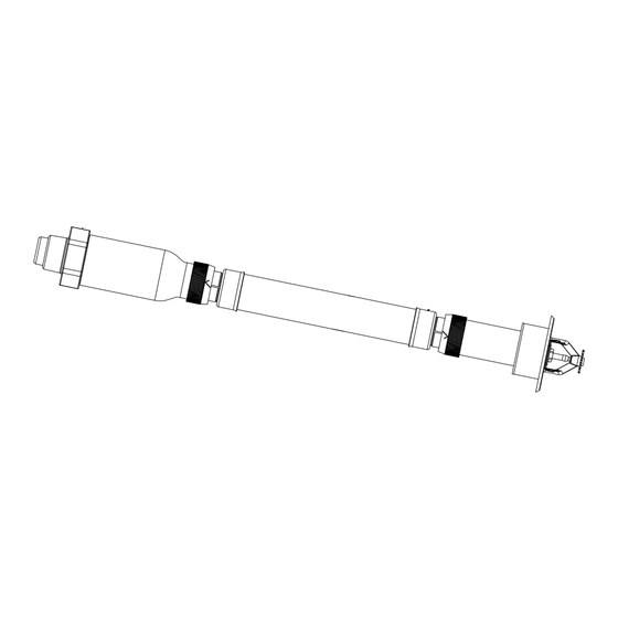
Style VS1 Dry Sprinkler
™
• Read and understand all instructions before attempting to install any Victaulic
• Wear safety glasses, hardhat, and foot protection.
• These installation instructions are intended for an experienced, trained installer.
• The installer shall understand the use of this product and why it was specified for the particular
application.
• The installer shall understand common industry safety standards and potential consequences of
improper product installation.
• It is the system designer's responsibility to verify suitability of stainless steel flexible hose for use
with the intended fluid media within the piping system and external environment.
• The material specifier shall evaluate the effect of chemical composition, pH level, operating
temperature, chloride level, oxygen level, and flow rate on stainless steel components to confirm
system life will be acceptable for the intended service.
Failure to follow these instructions could cause improper sprinkler operation and product failure,
resulting in death or serious personal injury and property damage.
K-Factor of Sprinkler:
5.6 US/80 metric
Maximum Number of 90° Bends:
4 Bends (UL) – All Hose Lengths
2 Bends (FM) – 38-inch/965-mm
Hose Length
3 Bends (FM) – 50-inch/1270-mm
Hose Length
4 Bends (FM) – 58-inch/1475-mm
Hose Length
Unheated
Space
Exterior
Unheated
Space
Exterior
WARNING
Flexible Hose Bend Characteristics:
NOTE: For out-of-plane (three-dimensional) bends, care shall be taken
to avoid imparting torque on the flexible hose.
Minimum
Bend Radius
90°
Minimum
Bend Radius
The following table is used when the ambient temperature is maintained
between 40° F/4° C and 60°F/16°C around the wet piping system.
Ambient
Temperature
Exposed Minimum Barrel Length "Y" inches/mm
Exposed to
Discharge End
of Sprinkler
°F/°C
40
4
30
-1
20
-7
10
-12
0
-18
-10
-23
-20
-29
-30
-34
-40
-40
-50
-46
-60
-51
NOTE: Exposed minimum barrel lengths are inclusive up to 30-mph/48-kph wind velocities
I-VICFLEX.VS1
®
VicFlex
2X
Minimum
Bend
Minimum
Radius
Bend
Radius
OR
Minimum
Bend Radius
Minimum
Bend Radius
Minimum
Bend Radius
40°F
50°F
4°C
10°C
0
0
0
0
0
0
0
0
4
0
100
0
8
1
200
25
12
3
300
75
14
4
350
100
14
6
350
150
16
8
400
200
18
8
450
200
20
10
500
250
20
10
500
250
I-VICFLEX.VS1_1
™
products.
Minimum
2X
Bend Radius
OR
Minimum
Bend Radius
60°F
16°C
0
0
0
0
0
0
0
0
0
0
1
25
3
75
4
100
4
100
6
150
6
150
Advertisement
Table of Contents

Related Manuals for Victaulic VS1 Series


Summary of Contents for Victaulic VS1 Series
- Page 1 Victaulic VicFlex Style VS1 Dry Sprinkler ® ™ WARNING • Read and understand all instructions before attempting to install any Victaulic ® VicFlex ™ products. • Wear safety glasses, hardhat, and foot protection. • These installation instructions are intended for an experienced, trained installer.
- Page 2 • Refer to the specific Victaulic product submittal for applications • Style VS1 Dry Sprinklers that have operated cannot be and listing information. Submittals can be downloaded at reassembled or reused, per NFPA requirements.
- Page 3 I-VICFLEX.VS1 / Victaulic VicFlex Style VS1 Dry Sprinkler / Installation Instructions ® ™ STYLE VB1 BRACKET ASSEMBLY DRAWING Item Description Style VB1 Bracket Hex Cap Screw Relocation Warning Label STYLE VB2 BRACKET ASSEMBLY DRAWING Item Description 24-inch/610-mm or 48-inch/1219-mm Square Bar*...
- Page 4 I-VICFLEX.VS1 / Victaulic VicFlex Style VS1 Dry Sprinkler / Installation Instructions ® ™ STYLE VS1 SPRINKLER ASSEMBLY PITCHING REQUIREMENTS SIDEWALL Continuous Downward Slope Inlet Heated Space Unheated Space Outlet ACCEPTABLE PITCH Inlet Low Point Outlet Heated Space Unheated Space UNACCEPTABLE PITCH...
- Page 5 I-VICFLEX.VS1 / Victaulic VicFlex Style VS1 Dry Sprinkler / Installation Instructions ® ™ FOR DRY SYSTEMS ONLY: • The Style VS1 Dry Sprinkler’s inlet shall be installed only into the outlet of a fitting (excluding elbows) or welded outlet that meets the dimensional requirements of ANSI B16.3 and ANSI B16.4, Class 125 and Class 150.
- Page 6 #10 x 1 1/2-inch long wood screws (for wood Screw for Installation joists/studs shown above) or two #10 x 1 1/2-inch long sheet metal screws (for metal joists/studs). NOTE: Victaulic does not supply Snap the bracket onto the wood screws or sheet metal screws.
- Page 7 I-VICFLEX.VS1 / Victaulic VicFlex Style VS1 Dry Sprinkler / Installation Instructions ® ™ STYLE VB2 AND STYLE VB3 BRACKETS – INSTALLATION FOR ASTM C635 CEILING SUSPENSION SYSTEMS INSTALLED WITH LAY-IN TILES (IN ACCORDANCE WITH Side Facing the ASTM C636 STANDARDS)
- Page 8 For complete contact information, visit victaulic.com I-VICFLEX.VS1 8919 REV D UPDATED 07/2018 Z000VS1000 VICTAULIC AND VICFLEX ARE REGISTERED TRADEMARKS OR TRADEMARKS OF VICTAULIC COMPANY AND/OR ITS AFFILIATED ENTITIES IN THE UNITED STATES AND/OR OTHER COUNTRIES. © 2018 VICTAULIC COMPANY. ALL RIGHTS RESERVED.
Need help?
Do you have a question about the VS1 Series and is the answer not in the manual?
Questions and answers