
Related Manuals for Texas Instruments CBL


Summary of Contents for Texas Instruments CBL
- Page 1 é SYSTEM G U I D E B O O K ® Table of Contents Guidebook Texas Instruments developed by: Instructional Communications © 1994–1997 by Texas Instruments Incorporated.
- Page 2 “as-is” basis. In no event shall Texas Instruments be liable to anyone for special, collateral, incidental, or consequential damages in connection with or...
-
Page 3: Table Of Contents
Table of Contents Safety Instructions ........... Chapter 1: What is the CBL System? An Overview The CBL System ..........Introduction to the CBL ........Special CBL Features ......... Connecting the CBL to a Calculator ......Chapter 2: Getting Started About the Display .......... -
Page 4: Safety Instructions
All voltage sources must be fully isolated from AC power lines. External Power ªCAUTION! Use the correct power adapter with the CBL. Using a wrong power adapter may cause damage to the adapter and to the unit. Analog Inputs ªCAUTION! It is very important that the ground connections of the analog inputs are never connected to different potentials. -
Page 5: Chapter 1: What Is The Cbl System? An Overview
Chapter 1: What is the CBL System? An Overview This chapter provides a brief overview of the CBL system — its components, its features, and how it works. Chapter Contents The CBL System ..........Introduction to the CBL ........Special CBL Features ......... -
Page 6: The Cbl System
The Calculator-Based Laboratory Systemé (CBLé) is a portable, handheld, battery-operated, data-collection device for collecting “real- world” data. The data collected with the CBL can then be retrieved by a calculator for further analysis. With the CBL system and appropriate sensors, you can measure motion, temperature, light, sound, pH, force, and more. -
Page 7: Introduction To The Cbl
To prolong battery life, the APD feature turns off the CBL automatically after 10 minutes without any activity. When you press P, the CBL will be exactly as you left it. The CBL does not APD while it is in mode, nor when is active. - Page 8 LCD display. But its real power is apparent when it is used interactively with a calculator. To control the CBL, you send a list such as {1,2,3} from a calculator to the CBL. The CBL interprets the lists as commands, which then control what the CBL does.
-
Page 9: Special Cbl Features
The CBL has a feature called Automatic Probe Identification AutoIDENT ). This lets the CBL automatically identify specific probes connected to the CBL. When you connect any of the provided TI probes to a CBL channel, the AutoIDENT feature does the following: ¦... - Page 10 Summary On the following pages you will learn more about the CBL and how to use a calculator to send commands and retrieve collected data. Although the CBL can perform complex experiments and complex operations, its use is simplified by many built-in automatic features and supplied programs.
-
Page 11: Connecting The Cbl To A Calculator
To prolong the life of batteries, the APD feature turns off the CBL automatically after 10 minutes without any activity. When you press P, the CBL will be exactly as you left it. The CBL does not APD while it is in... - Page 12 CBLé System Guidebook...
-
Page 13: Chapter 2: Getting Started
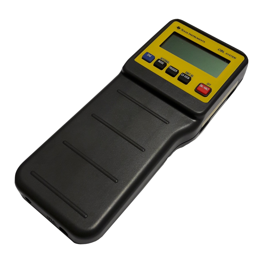
Chapter 2: Getting Started This chapter describes the contents of the display, the functions of the keyboard keys, and the six probe connections. Chapter Contents About the Display ..........About the Keyboard .......... About the Probe Connections ......... CBLé System Guidebook... -
Page 14: About The Display
. For example, the TI temperature probe measures the Ω Ω resistance of a thermistor when measuring temperature—the indicator is lit in and the ºC indicator is lit in . The resistance measured by the CBL is converted into temperature units. CBLé System Guidebook... -
Page 15: About The Keyboard
Keypress Functions Description Selects the function above M, O, and P. Toggles the CBL between Multimeter mode and Communications mode. In Communications mode puts the CBL in Internal INTERNAL mode. M or L returns the CBL to INTERNAL Communications mode... - Page 16 TI-85 because programming commands to send and receive data are not provided. Turns the CBL on. If the CBL is on, aborts any pending operation and stops data sampling. Any data collected is saved in the CBL and is available to be retrieved into the calculator.
-
Page 17: About The Probe Connections
The labeling for DIG IN DIG OUT is blue and matches the blue band on the cable in the CBL digital probe kit (page 85). Note: The included voltage probe (for ±10 Volts) can only be used on Analog Inputs... - Page 18 CBLé System Guidebook...
-
Page 19: Chapter 3: Using The Cbl System
Chapter 3: Using the CBL System This chapter describes how the CBL is set up and controlled by commands sent from a connected calculator. Parameter descriptions are provided for each of the commands. Chapter Contents What a Typical Program Might Include ...... -
Page 20: What A Typical Program Might Include
What a Typical Program Might Include About a Typical Program Format Programs are created on a calculator to set up the CBL operations for the experiments that you want to perform. A typical CBL program format might include the following basic tasks: 1. -
Page 21: About Automatic Probe Identification (Autoident)
AutoIDENT the CBL when connected to , or (analog channels), or to the ultrasonic channel. Each of the three TI probes provided with the CBL contain an AutoIDENT resistor. When an AutoIDENT probe is detected, the CBL sets the proper operation, loads a conversion equation into memory for the selected channel, and turns on the Conversion Equation for that channel. -
Page 22: Understanding Modes
Understanding Modes Communications Mode and Operating Conditions When the CBL is on, it is in one of three operating modes: . M or L [ Communications, Multimeter , or Internal INTERNAL] controls the mode. Communications mode is the default operating mode for collecting data. - Page 23 CBL to measure frequency as a stand- alone device. This is shown in the display MULTIMETER example to the right. If the CBL is connected to a calculator, commands in Multimeter Mode Setup ( CMD6 , page 52) also select multimeter operations.
-
Page 24: Understanding Cbl Commands
Understanding CBL Commands What are CBL Commands? Commands are sent to the CBL as a list. A command number is always the first integer in the list. CBL command numbers are single-digit integers that represent operations as shown in the table below. There are eight commands that are used to control the CBL. - Page 25 The maximum number of elements that can be in a command list is 25. If a list sent to the CBL contains more than 25 elements, the CBL ignores the entire list, and the calculator resumes operation at the next program instruction.
- Page 26 Assume the CBL receives two one-parameter commands as successive lists as shown by the following: :{1}→ → L:Send(L) :{3}→ → L‚:Send(L‚) The CBL interprets the first list ({1}) as a Channel Setup command and performs the following default operations: 1. Selects to collect data.
-
Page 27: About Cmd0-All Clear
CMD0 clears the unit of all previous data and resets all channels to their default settings. The only element in the list is a zero. When you send a to the CBL: CMD0 ¦ All channel indicators are turned off. -
Page 28: About Cmd1-Channel Setup
CMD1 a probe connected for collecting data. This command clears all previously collected data from the CBL. The first element in the list must be a 1 to designate CMD1... - Page 29 Statistics (mean, standard deviation, minimum, maximum) Derivatives and statistics are computed on values after the conversion equation has been applied. When derivatives are requested, Relative Record Time ( CMD3 ) is automatically turned on. CBLé System Guidebook...
- Page 30 0 (zero) turns it off, and 1 turns it on. (Default: Conversion Equation is a CBL feature that converts a measured physical unit such as volts or ohms into a more useful measurement unit such as Newtons or degrees Celsius.
- Page 31 AutoIDENT defaults to meters.) Meters Feet Note: The CBL uses 343 meters/second, the speed of sound at a pressure of 760 millimeters of mercury at 20ºC, for ultrasonic motion computations. Post-Processing This parameter lets you select the type of processing that is performed after the data has been collected.
- Page 32 Zero (0) turns it off, and 1 turns it on. (Default: Conversion Equation for the ultrasonic channel is a CBL feature that converts a measured distance in meters or feet to another measurement unit. The equation types are defined in...
- Page 33 Turns off the conversion equation and the indicator for that channel. ¦ Clears data for that channel. ¦ Conversion equation remains loaded, but is not active. ¦ For Channel = 0, the above operations affect all channels. Additionally, Record Time is turned off. CBLé System Guidebook...
- Page 34 (Sample and Trigger Setup) you define six statistic points to collect. The CBL collects 30 data samples (6 statistic points Q 5 data samples). The data that is returned to the CBL consists of four lists (mean, standard deviation, minimum, maximum) with each list containing six elements.
- Page 35 Select CH31 Number of data elements. Select output data element to be digital pattern corresponding to 1111. {1,31,4,0,1, Channel Setup command. 2,3} Set up CH31 Number of data elements. 0,1,2,3= Output 0,1,2,3 where: 0=0000, 1=0001, 2=0010, 3=0011. CBLé System Guidebook...
-
Page 36: About Cmd2-Data Type And Display Setup
Data Type With the exception of picture data, all data is stored in the CBL as a sequence of real numbers. This parameter lets you determine if the data will be stored as on the calculator as a list, matrix, or picture. - Page 37 This picture-only parameter sets the maximum Y value for picture data. Enter a real number greater than Ymin . (Default: Note: Ymin Ymax , and Xmin Xmax (on next page), are Window variables on a calculator, except on the TI-85 where they are Range variables. CBLé System Guidebook...
- Page 38 Examples: Data Type Setup Instruction {2,1} 2= Data Type and Display Setup command. 1= Select list data type using the default to display lowest active channel data on the CBL. {2,2,3} 2= Data Type and Display Setup command. 2= Select matrix data type.
-
Page 39: About Cmd3-Sample And Trigger Setup
CMD3 List Syntax {3,sample_time,number_samples,trigger_type,trigger_channel,trigger_ threshold,prestore, external_clock,record_time,filter} Note: The last list sent to the CBL must be a Sample and Trigger Setup command ( CMD3 ). This list should be sent by itself and must be the last setup command sent to the CBL before data collection begins. - Page 40 Trigger Type This parameter lets you select a specific point at which to start collecting data. You can trigger CBL to start collecting data at a specific point on the actual data, or on an external clock. The function performed...
- Page 41 CMD1 . (Default: Triggers on Triggers on Triggers on Triggers on an external clock signal. This trigger can be one of two physical signals that is determined by the External Clock Source parameter (page 44). CBLé System Guidebook...
- Page 42 Threshold and the operation selected in CMD1 , you will get an E.36 error message (page 57). There are two types of thresholds that can be set—hardware triggering and software triggering. (Refer to page 71 for additional information.) CBLé System Guidebook...
- Page 43 For example, a prestore data value of 10 results in 10% of the data being collected before triggering and 90% of the data being collected after triggering. Note: This parameter is ignored if Post-Processing is 3 (Statistics) in CMD1 CBLé System Guidebook...
- Page 44 ) should normally be selected when using an external clock source. Record Time This parameter lets you specify whether CBL records absolute or relative time during data collection. (Default: None. No time value is recorded. Absolute. Records the actual time in seconds from the start of data collection.
- Page 45 This “end effect” affects the filtered data at the beginning and end of the data range for (n-1)à2 points, where n is the number of points in the filter. CBLé System Guidebook...
- Page 46 Default values used for trigger and remaining parameters. {3,.0002,99, Sample and Trigger Setup command. Take a sample every 200 msec. 2,1,2.9} .0002= Collect 99 samples. Software triggering on rising edge. Trigger on 2.9= Trigger when voltage exceeds 2.9 Volts. CBLé System Guidebook...
-
Page 47: About Cmd4-Conversion Equation Setup
11 Reciprocal logarithmic 5 Logarithmic 12 Steinhart-Hart model * Conversion Equation is still enabled if selected in CMD1 and the EQ indicator in the display remains on. Note: Refer to “Conversion Equation Reference Information” in Appendix A. CBLé System Guidebook... - Page 48 This equation is a Type 3 equation, power, K , where K = 2750 and = L1.3. {4,1,3,2750, 4= Conversion Equation Setup command. L1.3} 1= Set up equation 1 (for 3= Set equation type to Power. 2750,L1.3= Set constants. Set K =2750 Set K =L1.3 CBLé System Guidebook...
-
Page 49: About Cmd5-Data Range Setup
99th sample. The CBL only stores the relative record time and computes the absolute time as each list or matrix is requested. If you need absolute time with... - Page 50 Data End is set to 99 for a list or 255 for a matrix. If the number of elements is greater than 99 for a list or 255 for a matrix, Data End is set to Data Begin plus 99 or 255. CBLé System Guidebook...
- Page 51 {5,11,3} Data Range Setup command. Retrieve data from channel. SONIC Retrieve unfiltered raw collected data (ignore filter setting)*. {5,-1} Data Range Setup command. L1= Retrieve recorded time*. * Retrieves data from the first to the last sample. CBLé System Guidebook...
-
Page 52: About Cmd6-Multimeter Mode Setup
6 to designate CMD6 List Syntax {6,set_reset,operation} Note: Pressing M lets you use the CBL in Multimeter mode as a stand-alone device without requiring setup commands from the calculator. Set/Reset This parameter lets you set or reset the Multimeter mode. (Default:... - Page 53 CBL. {6,1,2} 6= Multimeter Mode Setup command. 1= Set to Multimeter mode. 2= Measure voltage (±10 Volts) from This example sets up the CBL according to the resistance AutoIDENT sensed. With the TI temperature probe connected to , resistance is measured and converted to temperature in ºC.
-
Page 54: About Cmd7-Request Status
CH11 (999 Kohms = open) ¦ List of all active channels To create a list showing the system status of the CBL and to clear any error messages, send a , and then retrieve the list. Any error CMD7 condition except (Power-on Short, page 57) is cleared, when the list is retrieved. -
Page 55: Appendix A: Reference Information
... Clock-In Line Operation ........Clock-Out Line Operation ........Digital Output Buffer ........Determining the Minimum Sample Time ....Hardware Triggering ........Software Triggering ........Measuring Period and Frequency ......Asynchronous/ Synchronous Triggering vs. Record Time ..CBLé System Guidebook... -
Page 56: Error Conditions
Error Conditions Error and Status Messages When the CBL detects an error, it displays a coded error message from E.05 E.63 . In most cases, the first digit denotes the command in which the error occurred; the second digit denotes the parameter number where the error occurred. - Page 57 Invalid Multimeter mode operation. (Must be an integer from 1–8.) E.63 Power-on Short. The CBL detected a short on one or more of the +5 Volt DC supply pins, or a total current drain greater than 120 mA. CBLé System Guidebook...
-
Page 58: Ti Probes
The range of light over which the probe is sensitive is 10µW/cm to 1mW/cm AutoIDENT resistor in the probe causes the CBL software to automatically convert the measured voltage to mW/cm units. The probe is direction dependent and achieves the highest output when the end of the probe is pointed directly at the light source. - Page 59 Steinhart-Hart equation (refer to the table below). At 25°C, the resistance is 20 Kohms and the sensitivity is approximately 4.3% per °C. The CBL measures the thermistor as a resistance. The AutoIDENT resistor contained in the probe causes the CBL software to automatically convert the measured resistance to °C.
- Page 60 TI Probes (Continued) Temperature Resolution Temperature resolution on the CBL is represented by the chart shown below. For example, the resolution at L20ºC is about 0.29, at 0ºC about 0.15, at 20ºC about 0.1, and at 70ºC about 0.2. Temperature Probe and Chemical Tolerance The TI temperature probe was tested with chemicals at room temperature and at the chemical’s boiling temperature.
- Page 61 IDENT values are resistance values in ohms (tolerance ±5%). Operation 3 is a mathematical conversion of voltage to a current reading (1V=1A). There is no circuitry inside the CBL to convert current to voltage; this must be done in the external probe.
- Page 62 To connect custom-designed probes or other circuits to the analog input channels, the digital input channel, or the digital output channel on the CBL, you can purchase an analog probe kit, or a digital probe kit from TI or its Instructional Dealers. (Refer to page 87 for ordering information.) Each probe kit includes a four-foot length of telephone cable and a connector attached to one end.
- Page 63 Input impedance: 740KJ to 2.0 Volts 748KJ to 0.03 Volts Note: Due to a floating internal reference voltage, it is normal for the CBL to measure about 30 mV (Vin-low) or 2.0 Volts (Vin) when no input is connected. ¦...
-
Page 64: Conversion Equation
In particular, some operations are not defined for negative arguments. The overall accuracy of the CBL does not guarantee that a precisely zero volt input will not be read as a slightly negative number. Therefore, if you are using a conversion equation that has this limitation, use input voltages with minimum values above zero. -
Page 65: Triggering With Prestore
where: T = The location in the list retrieved from the CBL of the first sample after the trigger event. L = The actual length of the list returned by the CBL (see next page). N = The number of samples requested in... - Page 66 Because the some calculators, such as the TI-82, only returns lists up to 99 elements, determining the actual length of the list collected by the CBL is difficult unless the number of samples requested is 99 or less. If CMD5 is used to change the data range, the T computed on the previous page could be outside the list retrieved from the CBL.
-
Page 67: Miscellaneous Reference Information
Note: In the case of real-time data collection, any value entered for the Sample Time parameter that is less than or equal to 0.20 causes the CBL to collect data at this maximum rate. CBLé System Guidebook... -
Page 68: Improving Data Collection Accuracy Using Pause
Improving Data Collection Accuracy Using Pause When the sample time specified in is faster than 0.003 seconds, CMD3 sample events can be affected by the CBL having to respond to a Get( Input "CBLGET" instruction from a calculator. If Record Time is on, discrepancies will be found in the collected data. -
Page 69: Digital Output Buffer
The drive (output current) capability for nibble data and the clock is shown by the following: ¦ > L6ma (negative current flow > 3.98 Volts @ I output-high output-high out of the CBL) ¦ < 0.26 Volts @ I < 6ma (positive current flow output-low output-low into the CBL port) -
Page 70: Determining The Minimum Sample Time
Determining the Minimum Sample Time Different minimum sample times apply depending on what is currently active on the CBL. Several conditions that affect minimum sample times are: number of active channels, what is being measured, status of record time, Statistics post-processing, etc. -
Page 71: Hardware Triggering
Hardware Triggering When you set hardware triggering to trigger on a specific voltage, the CBL selects one of seven voltage levels as the trigger point. These voltage levels are established by the Trigger Threshold parameter and are shown in the table below. -
Page 72: Measuring Period And Frequency
If the CBL is set up using CMD3 to make multiple measurements at a particular sample time, the CBL waits for the sample time that you specified after it completes the current measurement. It then initiates the next cycle of period/frequency measurement. The minimum sampling time for period and frequency is 0.25 seconds. - Page 73 0=Trigger channel not applicable; 1=Trigger at 1 Volt. Assume a ±10 Volt, 20 Hz sine wave is the input signal on pin 1. The CBL follows the sequence of steps indicated below when the first trigger occurs (a trigger occurs every 0.05 seconds).
-
Page 74: Asynchronous/ Synchronous Triggering Vs. Record Time
When no prestore is selected, the first sample time will be the trigger point. Its recorded time will not be the internal sample clock time because the CBL is always sampling on the internal clock interval that you selected, and is storing points (if you selected prestore) until the trigger event occurs. - Page 75 Trigger Threshold is set to 1.0 and Trigger Type is set to 2 (trigger on rising edge). The CBL will collect and store a sample every 10 seconds. The recorded time for each sample will be 10 seconds. The trigger event (signal rising through 1.0 Volts) occurs 1.5 seconds after the previous sample, so a...
- Page 76 CBLé System Guidebook...
-
Page 77: Command Tables
Appendix B: Command Tables The tables in this section provide a quick reference to CBL commands. Default values appear in boldface type. Contents CMD1—Channel Setup ........CMD2—Data Type and Display Setup ......CMD3—Sample and Trigger Setup ......CMD4—Conversion Equation Setup ...... -
Page 78: Cmd1-Channel Setup
2= d/dt and 2= Meters 3 = Feet 3= Stats (mean, standard deviation, minimum, maximum) Applies only to CH1 and CH2. Period and Frequency apply only to , and only can be active if Operation = 5 or 6. CBLé System Guidebook... -
Page 79: Cmd2-Data Type And Display Setup
PicY and PicX parameters only apply when Data Type is 3 (Picture). Collect X data from 1 to the number of samples defined in CMD3 from the specified Y channel. Collect X data as the recorded time selected in CMD3 CBLé System Guidebook... -
Page 80: Cmd3-Sample And Trigger Setup
L0.2, L1.0, L5.0 for voltage and corresponding values for current and resistance). The trigger threshold in the setup string is rounded to the nearest value. or Stats is requested, or number of samples is L1, the default (no filtering) is CH31 used. CBLé System Guidebook... -
Page 81: Cmd4-Conversion Equation Setup
(K 1 X) Exponential (K 1 /X Modified exponential Xƒ0 (K 1 X) Geometric X‚0 (K 1 /X) Modified geometric X>0 Reciprocal logarithmic ln(K X>0 Steinhart-Hart model (ln 1000X)+K (ln 1000X) X>0 * No restrictions other than overflow. CBLé System Guidebook... -
Page 82: Cmd5-Data Range Setup
Data Select = 3, 4, 5; ignore filter setting in CMD3 Data End must be greater than or equal to Data Begin (unless Data End = 0), and both must be less than or equal to the number of samples sent to the CBL in the last CMD3 CMD6—Multimeter Mode Setup... - Page 83 Appendix C: Service and Warranty Information This appendix contains information about batteries, and service and warranty information. Contents Battery and Adapter Information ......In Case of Difficulty .......... Service Information .......... One-Year Limited Warranty ........CBLé System Guidebook...
-
Page 84: Battery And Adapter Information
Operating Power Requirements The CBL is designed to operate with four AA alkaline batteries. Factors that affect battery life are the actual time that the CBL is on and the amount of current used by connected probes during your experiments. The display contains a low-battery icon ( ) to let you know when these batteries should be replaced. - Page 85 6 Volts DC output when plugged into an electrical wall outlet. The Texas Instruments model AC-9201 power supply is the only AC-to- DC power adapter approved for use with the CBL. The use of other power adapters is strongly discouraged. AC9201...
-
Page 86: In Case Of Difficulty
(page 11). Press P to abort any pending operation. Check calculator program for correct instructions and syntax used to send commands to the CBL and to retrieve data from the CBL. Make sure CBL is not in Multimeter mode... -
Page 87: Service Information
For information about available documentation ¦ For information about purchasing related products. For Technical Information If you have technical questions about the installation or use of the CBL, you can call the Technical Support Group of Customer Support at: 1.972.917.8324 Hours: 8:00 AM–4:30 PM CST on Monday–Thursday... -
Page 88: One-Year Limited Warranty
Texas Instruments shall not be liable for loss of use of the product or other incidental or consequential costs, expenses, or damages incurred by the consumer or any other user. - Page 89 A nibble is a 4-bit digital binary group. There are two nibbles to an 8-bit digital byte, and two bytes to a 16-bit digital word. Done The state of the CBL in which data collecting has ceased and data is ready to be sent to the calculator. CBLé System Guidebook...
- Page 90 Ready The state of the CBL immediately after a Sample and Trigger Setup command is sent from the calculator. The CBL is ready to collect data. Record Time A parameter in the Sample and Trigger Setup command that specifies whether CBL records absolute or relative time during data collection.
- Page 91 52 collection, 67 stat samples, 30 trigger channel, 41 trigger threshold, 42 CBL and a calculator, description, 7, 8 trigger type, 40 CH VIEW key, 16 units display, 48 Channel parameter, 28 Xmin, Xmax, 38...
- Page 92 External Clock-Out line, 68 data accuracy, 67 external power adapter. See AC adapter Data Begin parameter, 50 data conversion, 9 features, CBL, 9 Data Display Channel parameter, 37 Filter parameter, 45, 46 Data Elements parameter, 33 filtering algorithms, 45, 46...
- Page 93 Operation parameter sample programs, basic format, 20 CH1, CH2, CH3, 29 sample rate, maximum, 67 DIG IN, 32 sample rate, various CBL-CPs, 67 Multimeter mode, 52 sample time, 39, 70 SONIC, 31 Sample Time parameter, 39 using to clear channels, 32...
- Page 94 17 Units Display parameter, 48 valid sampling and triggering, 68 viewing collected data, 10 voltage probe, 61 warranty information, 88 website address, 87 Xmin/Xmax, parameter description, 38 XMIT-85 key, description, 16 Ymin/Ymax, parameter description, 37 CBLé System Guidebook...