
Subscribe to Our Youtube Channel
Related Manuals for Pyronix ATLAS 4


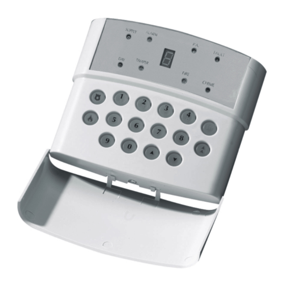
Summary of Contents for Pyronix ATLAS 4
-
Page 1: Programming Option
INSTALLATION INSTRUCTIONS Led Remote Keypad ® ® Pyronix Ltd. October 2001 This Product is approved for use in the Residential, Commercial and Light Industrial Environments Rins141 Issue 7... -
Page 2: System Option
This product is sold subject to our standard warranty conditions and is warranted against defects in workmanship for a period of 2 years. In the interest of continuing improvement of quality, customer care and design, Pyronix reserve the right to amend specifications without giving prior notice. -
Page 3: Table Of Contents
CONTENTS INTRODUCTION SAFETY ACCESS LEVELS Limited User Master User Engineer FUNCTIONAL DESCRIPTION Operating Modes Entry / Exit Mode ZONES Engineer Programmable Zones DIAL OUT REPORTING FUNCTIONS INSTALLATION AND WIRING Plan View With Cover Removed POWER CONNECTIONS Low Voltage a.c. Connections Battery Connections Bell, Strobe and Extension Speaker Connections Remote Keypad 'RKP' Conections... -
Page 4: System Option
10.27 Restoral Reporting Codes 10.28 Digicom Codes 10.29 Keyswitch Set Configuration 10.30 Group Reporting Telephone Allocation 10.31 Engineer NVM Reset 10.32 Follow Select 10.33 Exiting Engineer Mode LED FUNCTION SYSTEM FAULTS TECHNICAL SPECIFICATION 13.1 Power supply 13.2 Control PCB 13.3 Mechanical 13.4 Environmental... -
Page 5: Introduction
The Engineer cannot, however, set or unset the system. NOTE: The Atlas 4 uses the same software to control the panel as the Atlas 8, therefore any programming of zones will show all 8 zones, however only the first 4 are available for use. -
Page 6: Entry / Exit Mode
DIAL OUT REPORTING The Atlas 4 has the capability to send messages of alarm status to a Central Receiving Station. Every time the alarm status changes i.e. System Set/Unset, System Fault or Alarm Actuation a message is sent to the Central Receiving Station informing it of the status change. -
Page 7: Functions
Event Log The Atlas 4 control panel incorporates a memory log of the last 30 alarm events and is accessible to both Users and the Engineer. It will record Fire, Intruder, Personal Attack and Tamper alarms and also show if any of the 4 alarm zones have been triggered or omitted. - Page 8 24 Hour Test Dial: Dials the Central Monitoring Station every 24 hours. Dial In: This option will cause the Atlas 4 to respond to an incoming call in Answer Machine Compatible mode for a downloading or uploading operation. No Dial In: This option will cause the Atlas 4 to ignore incoming calls.
- Page 9 Central Monitoring Station Second Telephone Number: This is an alternative number which will be used by the Atlas 4 if the first telephone line is busy. If after four attempts connection with the first number fails then this number will be dialled.
-
Page 10: Installation And Wiring
System Option 4 Bell Squawk- Upon expiry of the exit time, if the panel sets OK the bell will emit a short duration of sound. It will also emit a short duration of sound upon disarming. Default value - OFF. Bell Time Minutes/Seconds- This option allows for very short bell durations. -
Page 11: Power Connections
To Battery Negative (-) In order for the Atlas 4 to operate if the mains power is cut a battery back-up is required. Refer to 9.6 for battery specifications. Connect the battery to the terminals marked +BAT- on the PCB. -
Page 12: Battery Capacity
End of line resistors When a Sensor, and tamper are wired into the same zone this is called an End of Line Zone (EOL). The Atlas 4 panel uses resistors on all of its end of line zones. Two resistor values are used, these are 2K2 and 4K7. -
Page 13: Double End Of Line Resistor Wiring Diagram
9.7.1 Atlas 4 End Of Line Resistor Wiring Diagrams Wiring unused zones. Wiring two or more sensors with end of line resistors to a single zone. NOTE: only one 2K2 resistor should be used per zone. The 2k2 resistor should be installed in the last detector in series to protect all the zone tamper wiring. -
Page 14: Atlas End Of Line Wiring Diagram
Page 14... -
Page 15: Programming
10.5 Programming Set Modes NOTE: The Atlas 4 uses the same software to control the panel as the Atlas 8, therefore any programming of zones will show all 8 zones, however only the first 4 are available for use. Any of the 4 zones may be programmed to be any one of the following:... -
Page 16: Setting The Alarm Bell Time
( minutes) followed by Incorrect entry gives an audible error tone and correct entry gives three bleeps. The alarm bell cut off time for the Atlas 4 is factory set to 20 minutes. 10.7 Setting Entry Time To set the required Entry time. -
Page 17: System Option 1
10.11 Programmable Output Enter followed by for following options: OFF (programmable output 1 not used). PIR remote LED enable. PIR latch memory. Output switch 5 secs. Output switch reflecting setting and unsetting of panel. Follow zone. Refer to 10.12.20 for Zone allocation. Follow line fail. -
Page 18: Customer Account Code
10.18 Central Monitoring Station Second Telephone Number Enter followed by the telephone number. (Up to 16 digits) By pressing the a " " displayed to cause a 2 second pause during dial out. Press to store entry. A number consisting of 16 digits will be stored automatically when the last digit is entered. 10.19 Customer Account Code (Issued by Central Monitoring Station) Enter... -
Page 19: Zone Tamper Alarm Report Codes
10.23 System Set / Unset Reporting Codes Enter Enter 2 digits for seven reporting codes. To disable an event insert blanks for both digits. e.g. 2 digit code Set A Set B Set C Set D Duress set Duress unset Confirmed alarm code To use HEX codes, use the key to select the character required and the... - Page 20 10.26 Maintenance and Priority Codes Enter Enter 2 digits for eight maintenance / priority codes. To disable an event insert blanks for both e.g. 2 digit code P.A. alarm entered at RKP Fire alarm entered at RKP Engineer mode entered Bell fuse failure Auxiliary fuse failure Battery trouble...
- Page 21 1 to 4 or if no zone is to be followed. 10.33 Exiting Engineer Mode Enter (Where is the 4 digit Engineer Code). Refer to the User Instructions for operating the Atlas 4 after programming. Rins141 Issue 7 Page 21...
- Page 22 SYSTEM FAULTS There are 6 fault conditions automatically detected by the Atlas 4. The user is informed of a fault via the fault LED. This LED will illumiate and an error tone will be emitted every 5 seconds when the panel is in day mode, Press a function key to stop the error tone.
-
Page 23: System Set / Unset Reporting Codes
ENGINEER QUICK REFERENCE PROGRAMMING SECTION Set A zone attributes. Set B zone attributes. Set C zone attributes. Set D zone attributes. Bell time Entry time Exit time Engineer code change Programmable output 1 Spare System option 1 System option 2 System option 3 Re-set First telephone number... - Page 24 COMMUNICATION PROGRAMMING Programmable Outputs Programmable Output 1 Default Off System Option 1 1 Default - End Line 2 Default - User Log Reset Disabled 3 Default - Tone dial 4 Default - Internal Sounder only on tamper activation System Option 2 1 Default - 24 hour test dial 2 Default - No dial in 3 Default - Standard Filters...
- Page 25 System Set / Unset Reporting Codes Set A Set B Set C Set D Duress Set Duress Unset Confirmed Alarm Code User Set ReportingCodes Set User 1 Set User 2 Set User 3 Set User 4 Set User 5 Set User 6 Set User 7/Keyswitch User Unset Reporting Codes Unset User 1...
- Page 26 Restoral Reporting Codes User code Restoral Bell Timeout Restoral Battery Restoral A.C. Restoral Test Transmission Digicom Codes Keyswitch Set Configuration Group Allocation Group 1 Group 2 Group 3 24hr. Test Call Page 26...
- Page 27 Rins141 Issue 7 Page 27...
- Page 28 Page 28...
Need help?
Do you have a question about the ATLAS 4 and is the answer not in the manual?
Questions and answers