HIKVISION DS-KH6320-LE1 Operation Manual
Network indoor station
Hide thumbs
Also See for DS-KH6320-LE1:
- Configuration manual (52 pages) ,
- Operation manual (34 pages) ,
- Manual (8 pages)
Table of Contents
Advertisement
Advertisement
Table of Contents

Related Manuals for HIKVISION DS-KH6320-LE1


Summary of Contents for HIKVISION DS-KH6320-LE1
- Page 1 Network Indoor Station Operation Guide...
- Page 2 WITHOUT LIMITATION, MERCHANTABILITY, SATISFACTORY QUALITY, OR FITNESS FOR A PARTICULAR PURPOSE. THE USE OF THE PRODUCT BY YOU IS AT YOUR OWN RISK. IN NO EVENT WILL HIKVISION BE LIABLE TO YOU FOR ANY SPECIAL, CONSEQUENTIAL, INCIDENTAL, OR INDIRECT DAMAGES,...
- Page 3 Network Indoor Station Operation Guide CONNECTION WITH THE USE OF THE PRODUCT, EVEN IF HIKVISION HAS BEEN ADVISED OF THE POSSIBILITY OF SUCH DAMAGES OR LOSS. YOU ACKNOWLEDGE THAT THE NATURE OF THE INTERNET PROVIDES FOR INHERENT SECURITY RISKS, AND HIKVISION SHALL NOT TAKE ANY...
- Page 4 Network Indoor Station Operation Guide Symbol Conventions The symbols that may be found in this document are defined as follows. Symbol Description Indicates a hazardous situation which, if not avoided, will or Danger could result in death or serious injury. Indicates a potentially hazardous situation which, if not Caution avoided, could result in equipment damage, data loss,...
- Page 5 Network Indoor Station Operation Guide Safety Instruction Warning • The working temperature of the device is from -10 ºC to 55 ºC. • All the electronic operation should be strictly compliance with the electrical safety regulations, fire prevention regulations and other related regulations in your local region.
- Page 6 Network Indoor Station Operation Guide • Please use the provided glove when open up the device cover, avoid direct contact with the device cover, because the acidic sweat of the fingers may erode the surface coating of the device cover. •...
- Page 7 Network Indoor Station Operation Guide Regulatory Information FCC Information Please take attention that changes or modification not expressly approved by the party responsible for compliance could void the user's authority to operate the equipment. FCC compliance: This equipment has been tested and found to comply with the limits for a Class B digital device, pursuant to part 15 of the FCC Rules.
- Page 8 Network Indoor Station Operation Guide EU Conformity Statement This product and - if applicable - the supplied accessories too are marked with "CE" and comply therefore with the applicable harmonized European standards listed under the EMC Directive 2014/30/EU, RE Directive 2014/53/EU,the RoHS Directive 2011/ 65/EU 2012/19/EU (WEEE directive): Products marked with this symbol cannot be disposed of as unsorted municipal waste in the...
- Page 9 Network Indoor Station Operation Guide l'appareil ne doit pas produire de brouillage, et l'utilisateur de l'appareil doit accepter tout brouillage radioélectrique subi, même si le brouillage est susceptible d'en compromettre le fonctionnement. Under Industry Canada regulations, this radio transmitter may only operate using an antenna of a type and maximum (or lesser) gain approved for the transmitter by Industry Canada.
-
Page 10: Table Of Contents
Network Indoor Station Operation Guide Contents 1 About this Manual ..................1 2 Home Page & Buttons Introduction ............2 3 Local Operation ..................4 3.1 Call Settings ....................... 4 3.1.1 Add Contact ....................4 3.1.2 Call Resident ..................... 5 3.1.3 Call Indoor Extension/Indoor Station ............ - Page 11 Network Indoor Station Operation Guide 4.6.1 Search Call Logs ..................17 4.6.2 Search Notice ..................18 A. Communication Matrix and Device Command ........21...
-
Page 12: About This Manual
Network Indoor Station Operation Guide 1 About this Manual Get the manual and related software from or the official website (http:// www.hikvision.com). Product Model DS-KH6320-LE1/DS-KH6320-LSE1/DS- Network Indoor Station KH6220-LE1... -
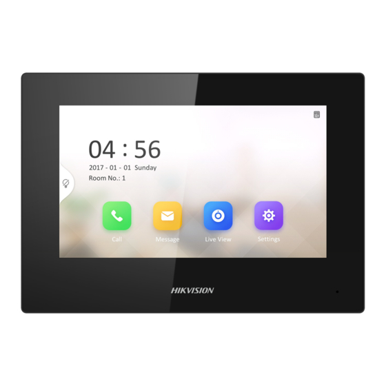
Page 13: Home Page & Buttons Introduction
Network Indoor Station Operation Guide 2 Home Page & Buttons Introduction Home Page Introduction Figure 2-1 Home Page Call You can call residents, add contacts, and view call logs. Message You can view notices, alarm logs and visitor messages. Live View You can unlock the door remotely while monitoring. - Page 14 Network Indoor Station Operation Guide Note Elevator control, management center and alarm functions are disabled by default. You should tap Settings → → Preference to enable the functions. Buttons Introduction There are 4 buttons on the front panel of the indoor station without touch screen.
-
Page 15: Local Operation
Network Indoor Station Operation Guide 3 Local Operation 3.1 Call Settings 3.1.1 Add Contact Steps 1. Tap Call → to enter the contact list page. Figure 3-1 Contact List 2. Tap + to pop up the contact adding dialog. Figure 3-2 Add Contact... -
Page 16: Call Resident
Network Indoor Station Operation Guide 3. Enter the contact name and phone No. Note The phone No. is the number you created when registering SIP account. 4. Tap OK to save the settings. Note Up to 200 contacts can be added. 3.1.2 Call Resident Steps 1. -
Page 17: Call Indoor Extension/Indoor Station
Network Indoor Station Operation Guide Note • The maximum two-way communication duration is 1800 seconds. • The floor No. should be less than 3 digits. Floor No. rangs from 0 to 999. Room No. ranges from 1 to 9999. 3.1.3 Call Indoor Extension/Indoor Station If you install indoor station and indoor extensions at home, you can call the indoor extension via your indoor station, and vice versa. -
Page 18: View Call Logs
Network Indoor Station Operation Guide Note • The maximum communicating duration between 2 indoor station is 1800 s. • The maximum communicating duration between indoor station and door station is 120 s. • The maximum communicating duration between indoor station and main station is 120 s. -
Page 19: Live View
Network Indoor Station Operation Guide • Hold a piece of call logs, and tap Delete to delete. • Tap Clear to delete all pieces of call logs. 3.2 Live View On the live view page, you can view the live video of added door station and network camera. -
Page 20: Disarm Your Room
Network Indoor Station Operation Guide Before You Start • Tap Settings → → Preference → Alarm to enable the Alarm function. • You should create an arm/disarm password. Please refers to Password Settings for the details. Steps 1. Tap to enter the scene page. 2. -
Page 21: Information Management
Network Indoor Station Operation Guide Figure 3-5 Arming Mode Settings 3. Arm the selected zone. Note • Zones are configurable on the arming mode page. • 24H alarm zone including smoke detector zone and gas detector zone will be triggered even if they are disabled. •... - Page 22 Network Indoor Station Operation Guide Figure 3-6 Alarm Log Delete: Hold an item, you can select it to delete. Clear: Hold an item, you can clear all logs. Note Indoor extension only supports alarm log.
-
Page 23: Remote Operation Via The Client Software
Network Indoor Station Operation Guide 4 Remote Operation via the client software The Video Intercom module provides remote control and configuration on video intercom products via the iVMS-4200 client software. 4.1 Call Indoor Station Steps 1. On the main page, click Access Control → Video Intercom to enter the Video Intercom page. -
Page 24: Receive Call From Indoor Station/Door Station
Network Indoor Station Operation Guide 4.2 Receive Call from Indoor Station/Door Station Steps 1. Select the client software in the indoor station or door station page to start calling the client and an incoming call dialog will pop up in the client software. Figure 4-2 Incoming Call from Indoor Station 2. -
Page 25: View Call Logs
Network Indoor Station Operation Guide You can get the live view of the door station and outer door station in the Main View module and control the door station and outer door station remotely. In the Main View module, double-click a door station or outer door station device or drag the device to a display window to start the live view. - Page 26 Network Indoor Station Operation Guide Steps 1. On the main page, click Access Control → Video Intercom to enter the Video Intercom page. 2. Click Notice to enter the Release Notice page. Figure 4-4 Release Notice 3. Click Add on the left panel to create a new notice.
- Page 27 Network Indoor Station Operation Guide Figure 4-5 Create a Notice 4. Edit the notice on the right panel. 1) Click ... on the Send To field to pop up the Select Resident dialog. 2) Check the checkbox(es) to select the resident(s). Or you can check the All checkbox to select all the added residents.
-
Page 28: Search Video Intercom Information
Network Indoor Station Operation Guide Note Up to 6 pictures in the JPGE format can be added to one notice. And the maximum size of one picture is 512KB. 7) Enter the notice content in the Information field. 8) Optional: You can also click Clear to clear the edited content. Note Up to 1023 characters are allowed in the Content field. - Page 29 Network Indoor Station Operation Guide Figure 4-6 Search Call Logs 3. Set the search conditions, including call status, device type, start time and end time. Call Status Click to unfold the drop-down list and select the call status as Dialed, Received or Missed.
- Page 30 Network Indoor Station Operation Guide Steps 1. On the main page, click Access Control → Video Intercom to enter the Video Intercom page. 2. Click Notice to enter the Notice page. Figure 4-7 Search Notice 3. Set the search conditions, including notice type, subject, recipient, start time and end time.
- Page 31 Network Indoor Station Operation Guide 7. Optional: Click Export to export the notices to your PC.
- Page 32 A. Communication Matrix and Device Command Communication Matrix Scan the following QR code to get the device communication matrix. Note that the matrix contains all communication ports of Hikvision access control and video intercom devices. Figure A-1 QR Code of Communication Matrix Device Command Scan the following QR code to get the device common serial port commands.
- Page 33 UD20153B...
Need help?
Do you have a question about the DS-KH6320-LE1 and is the answer not in the manual?
Questions and answers