Advertisement
Quick Links
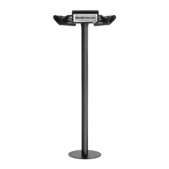
Solaira Malibu
Post Kit with Alpha H1 Heaters
SHORTWAVE INFRARED HEATERS WITH POST & INCOMING TERMINAL BOX KIT
FOR: INDOOR USE - COMMERCIAL AND INDUSTRIAL ONLY
OUTDOOR USE - RESIDENTIAL, COMMERCIAL AND INDUSTRIAL
FOR USE IN NON-HAZARDOUS AREAS ONLY
Post and weatherproof terminal box rain tested to:
UL 2021 4th Edition by CSA Montréal Lab.
Alpha H1 Heaters fitted are approved to:
CAN.CSA-C22.2 No. 46-13 & UL 2021 3rd Edition.
INFORESIGHT CONSUMER PRODUCTS INC.
125 Traders Blvd. E Unit # 4, Mississauga, Ontario L4Z 2H3
Email: info@solairaheaters.com - Website: www.solairaheaters.com
I M P O R TA N T - S AV E T H E S E I N S T R U C T I O N S F O R F U T U R E R E F E R E N C E
Reference Manual
MAL 45240 208/240V 4.5kW (3 × 1.5kW)
MAL 60240 208/240V 6.0kW (3 × 2.0kW)
Tel: 905-568-7655 - Fax: 905-568-7521
247748
Advertisement

Related Manuals for Solaira Malibu MAL 45240


Summary of Contents for Solaira Malibu MAL 45240
- Page 1 Reference Manual Solaira Malibu Post Kit with Alpha H1 Heaters MAL 45240 208/240V 4.5kW (3 × 1.5kW) MAL 60240 208/240V 6.0kW (3 × 2.0kW) SHORTWAVE INFRARED HEATERS WITH POST & INCOMING TERMINAL BOX KIT FOR: INDOOR USE - COMMERCIAL AND INDUSTRIAL ONLY...
- Page 2 I M P O R TA N T I N S T R U C T I O N S I M P O R TA N T I N S T R U C T I O N S I M P O R TA N T I N S T R U C T I O N S I M P O R TA N T I N S T R U C T I O N S When using electrical INFRARED HEATERS, basic precautions...
- Page 3 I M P O R TA N T I N S T RU C T I O N S I M P O R TA N T I N S T RU C T I O N S I M P O R TA N T I N S T RU C T I O N S I M P O R TA N T I N S T RU C T I O N S 11.
- Page 4 I N T R O D U C T I O N The Malibu outdoor heater produces radiant heat like the sun, warming people and objects and not the air in between, providing the only form of heat that will not blow away with wind or drafts.
- Page 5 K I T C O N T E N T S ALPHA H1 WEATHER- INFILL PIECE DEBRIS PROTECTION PROOF CSA APPROVED 3 - OFF COVER HEATER 1 - OFF 3 - OFF INFILL & COVER FIXING KIT HEATER FIXING KIT 1 - OFF 1 - OFF JOINING INSERT...
- Page 6 A S S E M B LY C AU T I O N C AU T I O N C AU T I O N C AU T I O N The following procedure should be carried out by a qualified person only in accordance with the National Electric Code (NEC) and local codes.
- Page 7 4. Take the terminal box/bracket assembly (Fig. 4) and place in the space where the 3 × curved tubes (arms) come together as shown in Fig. 5 with the lid on the top. Note. The nuts on the two side strain relief glands can be removed to provide better access to the screw slots.
- Page 8 7. Fit a Alpha H1 heater to a curved tube by placing the middle bracket of the heater into the tube opening and push an M8 screw through the underside of the tube. Place a washer and an M8 Nyloc nut on the end of the screw (Fig. 7a) taking care not to drop the nut down the tube.
- Page 9 9. Cut the heater cords to the correct length for connecting into the terminal box. Then pass cords through respective strain relief glands into the box. Strip back cable to relevant length. GROUND POST Fig. 9 Fig. 10a Fig. 10b 10.
- Page 10 12. Fully tighten the strain relief gland nuts and the terminal box lid can be fitted as shown in Fig. 12. Fig. 12 13. Fit a zip tie around the curved arms at the base plate to keep them together when the assembly is moved in the installation stage (on the next page).
- Page 11 I N S TA L L AT I O N I N S T R U C T I O N S Always allow the heater to cool before attempting to reposition/move. Never attempt to move the heater while it is switched on! Observe the minimum safe distance between the heater body and inflammable surfaces and objects when mounting.
- Page 12 3. Slide a body pole (with joining pieces fitted) onto the three upright pieces on the base plate by matching the flat faces on the tube with the flat faces of the upright piece, feeding the supply cable through. Secure in place with 3 X M8 × 20 button head socket screws placing a M8 spring/split washer behind the head of the screw on all faces.
- Page 13 5. Feeding the supply cable through the heater assembly, pass the cable through the M25 cable gland and through the terminal box. Locate the heater assembly onto the joining pieces of the body pole assembly. Secure in place with 3 X M8 × 20mm button head socket screws, placing M8 spring/split washers behind the heads of the screws.
- Page 14 7. Replace the terminal box lid and fit the infill pieces by locating the lower tabs into the locating tabs on the curved arms. Once located the upper tabs can be screwed into position with M4 screws and shake-proof washers in the threaded holes. Repeat for the other sides (total of three).
- Page 15 G E N E R A L S I Z E S of 20 Ref No. 043477-EN Rev. A...
- Page 16 M AI N T E N A N C E NOTE: For replacement lamp emitters or spare parts please contact your local distributor quoting model type and rating from rating label. It is very important that your replacement lamp emitter is exactly the same as the one it was supplied with. Failure to fit the exact same type can cause the heater to prematurely fail.
- Page 17 R E P L A C I N G A L A M P E M I T T E R C AU T I O N C AU T I O N C AU T I O N C AU T I O N Switch off from the mains to the unit by locking off breaker before any attempts are made to replace a lamp emitter.
- Page 18 6. At the front of the heater, gently remove the wire guard by prizing it away from its locating holes at each end of the heater case (Fig. E). Fig. E 7. Remove the screw from the side reflector (Fig. F) and lift the side reflector up and away from the heater.
- Page 19 9. The lamp emitter can now be removed away from the heater leaving it ready to have the new lamp emitter fitted as shown in Fig. H. Fig. H 10. Refit the new lamp emitter in reverse order making sure that no wires can get trapped. Replace both ends side reflectors and their screws ensuring the lamp emitter is held firmly then fit any other parts.
- Page 20 I M POR TANT - SAV E T H ES E I N STR UCT ION S FOR FU TU RE R EF E RE NC E Solaira Malibu Post and weatherproof terminal box rain tested to: UL 2021 4th Edition by CSA Montréal Lab.
Need help?
Do you have a question about the Malibu MAL 45240 and is the answer not in the manual?
Questions and answers