Advertisement
Advertisement
Table of Contents

Related Manuals for Triplett 9005-A


Summary of Contents for Triplett 9005-A
- Page 1 TRIPLETT Model 9005-A Digital Multimeter Instruction Manual...
-
Page 2: Safety Rules & Warnings
11. Warranty 1: INTRODUCTION The Triplett Model 9005-A is a 3 1/2 digit, high reliability, handheld Digital Mul- timeter with a large 1.15" high Liquid Crystal Display. At its core is an LSI (Large Scale Integration) integrated circuit which uses dual slope A/D conversion for stability and accuracy. - Page 3 2.3 Do not use this meter with its case open, or with parts removed. Doing so may damage the meter and/or injure the user. 2.4 When using this meter in schools and workshops, responsible teachers or skilled personnel must control the usage of this meter. Failure to observe this precaution may result in damage to the meter or injury to the user.
- Page 4 2.13 Insert the test leads in the jacks specified in the instructions for performing particular tests. Inserting the test leads in incorrect jacks can damage the meter and/or injure the user. 2.14 Do not exceed the maximum voltage or current limitations of the meter (see product specifications).
- Page 5 2.24 Do not use this meter to make measurements in adverse environments such as rain, snow, fog, or locations with steam, explosive gases or dusts. Doing so may damage the meter and/or injure the user. 2.25 Do not use meter in condensing atmospheres. That is, do not use meter in conditions where ambient temperature and humidity could cause condensa- tion of water inside of meter.
- Page 6 2.34 Do not use this meter to measure current in circuits whose open circuit voltage exceeds 250V AC/DC. The meter’s fuses are rated at 250V max. Failure to observe this precaution may result in damage to the meter or injury to the user. 2.35 When you use the meter to check a high-voltage circuit, do not try to connect both test leads at once.
- Page 7 2.42 Avoid usage near strong magnetic fields (magnets, loudspeakers, transformers, motors, coils, relays, contactors, electromagnets, etc.). The meter may display readings that are in error, causing the user to misinterpret the hazards present. For example, the meter may indicate a low voltage when high voltages are actually present.
-
Page 8: International Symbols
3: INTERNATIONAL SYMBOLS The following International Symbols may be used in this manual and on the case of the meter to identify, caution, or warn the user of important product limitations or important operational procedures that must be followed to ensure safe usage of the product. -
Page 9: Specifications
Weight: 272 grams, 0.60 lbs. (w/ battery, w/o holster or leads) Battery: 1 standard 9 volt alkaline battery (Triplett PN 37-48) Battery Life: approx. 200 hours Fuse: 2A/250 volt FAST, 5 x 20mm fuse, for µ A & mA ranges... - Page 10 Note: a) The following accuracy specifications are valid at 23 degrees C, +/- 5 degrees C, Relative Humidity less than 75% b) The specifications are in the form “ +/- (x % of reading + LSD)” where LSD is “Least Significant Digit”. t i g ±...
- Page 11 2 µA 0 µA 1µA t i g ± 0 1 µA 1 µA t i g ± t i g ± 2 Ω 0 Ω t i g ± 2 Ω 1Ω t f a i t c 0 2 Ω 0 1 Ω...
-
Page 12: Power Button
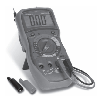
6: 9005-A FRONT PANEL 1) Liquid Crystal Display 2) POWER Button 3) Rotary Function / Range Switch 4) Holster 5) HOLD Button 6) Transistor Socket 7) Input Jacks... -
Page 13: Measurement Procedures
Failure to observe this precaution may result in damage to the meter or injury to the user. 7.2 Auto Power Off: The 9005-A has Auto Power Off. This power saving feature automatically turns the meter off 15 to 20 minutes after turning it on..thereby extending battery life. - Page 14 7.3.2 Set the RANGE switch to a V position. If the magnitude of the voltage is unknown, set the RANGE switch to the highest V position. If the input voltage is higher than the previously stated limits, do not attempt to measure! 7.3.3 Connect the test probes to circuit being measured.
- Page 15 7.4.3 Connect the test probes to circuit being measured. The LCD will display the AC voltage. 7.4.4 If the display indicates overrange, i.e. “1- - -”, disconnect the test probes from the circuit and rotate the RANGE switch to the next higher position. Reconnect the test probes to the circuit and observe the reading on the LCD display.
- Page 16 7.5.4 If the display indicates overrange, i.e. “1- - -”, disconnect the test probes from the circuit and reconnect the red test lead to the 10A jack. Set the RANGE switch to the 10A position, and reconnect the test leads to the circuit.
- Page 17 7.6.4 If the display indicates overrange, i.e. “1- - -”, disconnect the test probes from the circuit and reconnect the red test lead to the 10A jack. Set the RANGE switch to the 10 A position, and reconnect the test leads to the circuit.
- Page 18 Notes: a) The 2M, 20M, and 200M ranges require several seconds to stabilize. b) The 200M range reads 10 LSD high. To obtain an accurate reading, subtract 10 LSD from the indicated value on the LCD. c) To obtain the most accurate reading on the 200 Ω range, short the test leads together and note the “residual resistance”...
- Page 19 7.9.2 Set the RANGE switch to the Diode Test / Continuity Beeper “ ” range. 7.9.3 Connect the test probes to the device or circuit to be tested. To test a simple diode, connect the red test probe to the Anode of the diode and the black test lead to the Cathode (“banded”...
-
Page 20: Using The Holster
8: USING THE HOLSTER A protective holster is provided with the Model 9005-A. This vinyl holster pro- vides a measure of protection from the everyday rigors that products of this type are often subjected to. Molded into the holster are two holders for the test probes. When not in use, the test leads can be coiled around the meter and the probes snapped into these holders. -
Page 21: Maintenance
9: MAINTENANCE Your Triplett Model 9005-A DMM is a precision measuring instrument and, when used as described in this manual, should not require maintenance. However, periodic calibration of the meter will insure that it is accurate and per- forming in accordance with its design specifications. A one year calibration inter- val is suggested. - Page 22 9.1.4 Remove the 9 volt battery and replace with a fresh battery (PN 37-48). 9.1.5 Carefully install the fresh battery back into the meter, making sure that the battery wires will not be pinched when the case of the meter is reassembled.
- Page 23 (Triplett PN 10-4275) 10.4 Optional Clamp-On A “clamp-on” is available for measuring AC Current. The 9005-A is set to the 200mV AC range to use the clamp-on. 10.4.1 Model 10-N AC Current Clamp-On for measuring AC current up to 400A.
- Page 24 No representative of Triplett Corporation or any other person is authorized to extend the liability of Triplett Corporation in connection with the sale of its products beyond the terms hereof.
- Page 25 NOTES...
Need help?
Do you have a question about the 9005-A and is the answer not in the manual?
Questions and answers