
Related Manuals for Triplett 9055


Summary of Contents for Triplett 9055
- Page 1 TRIPLETT Model 9055 6-in-1 EnviroMeter with Sound Light, Temperature and Humidity Instruction Manual 84-896 10/10...
-
Page 3: Table Of Contents
TABLE OF CONTENTS TITLE INTRODUCTION………………………………………2 SAFETY INFORMATION …………………………4 FEATURES……………………………………………18 SPECIFICATIONS……………………………………19 CONTROL LOCATIONS AND DESCRIPTIONS…. 26 OPERATING INSTRUCTIONS …………………… 29 MAINTENANCE ………………………………………. 36 WARRANTY ……………………………………………38... -
Page 4: Introduction
1. INTRODUCTION The Triplett 9055 6-in-1 Digital Multi-Tester is an autoranging ruggedized 3-3/4 digit (4000 count) precision Digital Multimeter with a large backlit high contrast LCD display and expanded measurement capabilities. In addition to the measurements performed by conventional multimeters, the 9055 also measures Sound Level, Light Level, Humidity, and Temperature. - Page 5 The 9055 is well suited for use in all test environments, from occasional use in residential applications, to everyday use by installers, home theater technicians, security technicians, electricians, HVAC technicians, and other professionals in the electrical and electronics industry.
-
Page 6: Safety Information
S AFETY INSTRUCTIONS . . . . This meter has been designed with safety in mind, but like all products of this type, must be operated carefully to obtain the best performance and avoid injury. NEVER apply voltage or current to the meter that exceeds the following specified limits: Input Protection Limits Function... - Page 7 Read all instructions in this manual before using this meter. Failure to do so may result in damage to the meter or injury to the user. Prior to using the meter in any situation which could result in injury to the user, in order to verify that the meter is functional and producing a valid reading, test the meter on a circuit(s) known to have potentials equivalent to the potential that is to be...
- Page 8 Follow recommendations Trade Organizations or Regulatory Agencies whose scope encompasses the use of this meter. Failure to do so may result in damage to the meter or injury to the user. Do not open this meter for maintenance without first disconnecting the test leads from all external circuitry.
- Page 9 Check the condition of the test leads before making a measurement. Do not use the test leads if there is damaged insulation or exposed metal. Failure to observe this precaution may result in damage to the meter or injury to the user. 2.10 Make sure test leads are properly inserted and seated in the meter's input jacks.
- Page 10 Failure to observe this precaution may result in damage to the meter or injury to the user. 2.13 Insert the test leads in the jacks specified in the instructions performing particular tests. Inserting the test leads in incorrect jacks can damage the meter and/or injure the user.
- Page 11 2.17 Do not attempt to measure a voltage source with the test leads plugged into the meter's uAmA or 10A jacks. Doing so may damage the meter and/or injure the user. 2.18 Do not rotate the Function switch with the test leads connected to the circuitry to be tested.
- Page 12 hazard exists, when in fact, dangerous voltages or currents may be present. Failure to observe this precaution may result in damage to the meter or injury to the user. 2.22 Use caution when working with voltages above 25 volts AC or 35 volts DC. Such voltages may cause a life threatening electrical shock.
- Page 13 2.26 Do not use the meter if either the meter or the test leads are wet, either from exposure to the weather, or after cleaning the case of the meter. Doing so may cause injury to the user. 2.27 Do not attempt immediate use of the meter when bringing it from a cold environment to a warm environment.
- Page 14 2.30 Do not touch the metallic portion of one test lead if the other test lead is connected to a live circuit. The current from the live circuit may pass through the meter and appear on the unconnected test lead. Failure to observe this warning may result in user injury.
- Page 15 2.34 Do not use this meter to measure current in circuits whose open circuit voltage exceeds 600V AC/DC. The meter's fuses are rated at 600V max. Failure to observe this precaution may result in damage to the meter or injury to the user. 2.35 When you use the meter to check a high-voltage circuit, do not try to connect both test leads at once.
- Page 16 2.37 Do not use the meter if it does not appear to work correctly on all ranges and in all modes. Failure to observe this precaution may result in damage to the meter or injury to the user. 2.38 Do not use the meter if it has undergone long-term storage under unfavorable conditions.
- Page 17 2.41 To avoid damage to the meter and possible user injury, disconnect test leads from test points before changing the function/range. Failure to observe this precaution may result in damage to the meter or injury to the user. 2.42 Avoid usage near strong magnetic fields (magnets, loudspeakers, transformers, motors, coils, relays, contactors, electromagnets, etc.).
- Page 18 2.44 Avoid usage near strong RF fields (radio or television transmitters, walkie talkies, cellular phones, etc.). The meter may display readings that are in error, causing the user to misinterpret the hazards present. For example, the meter may indicate a low voltage when high voltages are actually present.
- Page 19 2.47 The Non-Contact AC Voltage Detector in the 9055 may not detect the presence of AC voltage in all situations. In particular, a twisted 3 phase cable tends to cancel out its electrostatic field, which can make the cable appear to be "dead". Use caution and good work practices at all times, even when the 9055 indicates that AC voltage is not present.
-
Page 20: Features
F EATURES . . . . • Deluxe Autoranging DMM with Enviro Measurement • Built-in Light Level Meter (Lux) • Built-in Sound Level Meter (dBC) • Built-in Ambient Temperature Meter (° F and ° C) • Built-in Humidity Meter (%RH) •... -
Page 21: Specifications
• Auto or Manual Ranging • Auto Power Off • Rugged Overmolded Case Design • Built-in Stand and Test Lead Holders • Fused uA, mA, and A Ranges • Overload Protected • Double Insulated • CE Rated (EMC / LVD) •... - Page 22 Storage temperature: 14 ° F to 140 ° F at less than 80 % relative humidity. Battery: Standard 9V, NEDA1604 or 6F22 battery. Dimensions: 6-5/8” x 3” x 1-7/8” Weight: Approx: 11.2 oz (including battery) The following accuracies are valid for 65 ° F to 83 ° F, less than 70 % RH Sound Level Range...
- Page 23 Photo detector: Silicon photo diode with filter mimicks spectral sensitivity characteristic of C.I.E. (International Commission on Illumination) photopia curve V (λ). Spectral Sensitivity (%) versus Wavelength (nm) % / nm 500 to 600 100% Humidity Range Resolution Accuracy 33% ~ 99% RH 1% RH 3.5% of rdg ±...
- Page 24 Internal Sensor in Meter (Room Temperature) Range Resolution Accuracy 32° F ~+122° F 0.1° F 3% of rdg ± 2 degrees 0° C ~+50° C 0.1° C 3% of rdg ± 1 degree DC Voltage Range Resolution Accuracy 400.0mV 0.1mV ±...
- Page 25 Frequency Range: 50 to 400Hz Overload Protection: 600V CAT IV AC/DC 1000V CAT III DC 700V CAT III AC DC Current Range Resolution Accuracy 400.0uA 0.1uA ± 1.0% of rdg ± 4 dgts 4000uA 40.00mA 10uA ± 1.2% of rdg ± 4 dgts 400.0mA 100uA 4.000A...
- Page 26 AC Response: 50 Hz to 400 Hz Maximum Input: 400mA AC/DC on uA / mA ranges, 10A AC/DC on 10A range (30 seconds max every 15 minutes). Resistance Range Resolution Accuracy 400.0Ω 0.1Ω ± 1.5% of rdg ± 4 dgts 4.000kΩ...
- Page 27 Frequency Range Resolution Accuracy 5.000Hz 0.001Hz 50.00Hz 0.01Hz 500.0Hz 0.1 Hz ± 1.2% of rdg ± 3 dgts 5.000kHz 1 Hz 50.00kHz 10Hz 500.0kHz 100Hz 5.000MHz 1kHz ± 1.5% of rdg ± 4 dgts 10.00MHz 10KHz Sensitivity: 0.5V RMS at frequencies less than 1MHz ; 3V RMS at frequencies greater than 1MHz ;...
-
Page 28: Control Locations And Descriptions
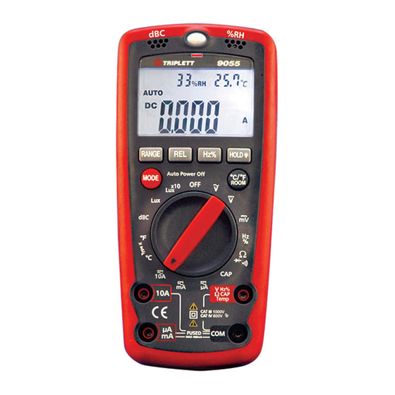
CONTROL LOCATIONS AND DESCRIPTIONS... - Page 29 CONTROL LOCATIONS AND DESCRIPTIONS (cont.) Humidity & Temperature Sensor LCD Display Function Switch V/Hz%/ /Cap/ Temp Input Jack COM Input Jack uA/mA Input Jack 10A Input Jack Sound Level Sensor Light Level Sensor 10. Hz/% Button Selects Hz or Duty Cycle measurement when DMM is set to Hz/% range or AC Voltage or AC Current ranges.
- Page 30 14. Range Button Press to change from Autoranging to manual ranging. Press repeatedly to select the desired range. To return to Autoranging, press and hold the button until ‘Auto’ appears in the display. The LCD annunciators indicate the selected range. 15.
-
Page 31: Operating Instructions
OPERATING INSTRUCTIONS Measuring Sound Level 1. Set the Function Switch to the “dBC” position. 2. Hold the face of the meter perpendicular to the sound source. 3. The sound level will be displayed. Note: Strong wind (over 20mph) striking the microphone can cause reading errors. - Page 32 Measuring Temperature (Room) Place meter in the location to be measured. Allow meter to set in this location for at least 1 hour. Set the Function Switch to any position other than OFF. Read Room Temperature from the LCD. Note: Select °...
- Page 33 Measuring DC Voltage Insert the black test lead into the COM jack and red test lead into the “V/Hz%/ /Cap/ Temp” jack. Set the Function Switch to the DCV range and connect the test leads across the source or load under measurement.
- Page 34 Notes: Use the RANGE button to manually select the desired ACV range. The 400mV AC range can only be selected with the RANGE button. Use the REL button to ‘zero’ a reading. Use the Hz% button to measure the Frequency or Duty Cycle of the AC voltage.
- Page 35 Connect the red test probe tip to the positive side of the circuit. 8. Apply power to the circuit. 9. Read the current on the LCD display. Notes: Use the RANGE button to manually select current ranges. Use the REL button to ‘zero’ a reading. Use the Hz% button to measure the Frequency or Duty Cycle of an AC current.
- Page 36 Measuring Frequency 1. Insert the black test into the COM jack and the red test lead into the V/Hz%/ /Cap/° C jack. 2. Set the Function Switch to the ‘Hz %’ position. 3. Touch the test probe tips to the circuit under test. 4.
- Page 37 4. Touch the test probes to the diode under test. Forward voltage will typically indicate 0.400 to 0.700V. Reverse voltage will indicate “OL”. Shorted devices will indicate near 0V and an open device will indicate “OL” in both polarities. Note: DO NOT CONNECT THE TEST LEADS TO ANY PART OR CIRCUIT WITH VOLTAGE PRESENT.
-
Page 38: Maintenance
It is normal for the AC Voltage Sensor LED to light when measuring AC voltages with the test leads. 7. MAINTENANCE Your Triplett Model 9055 DMM is a precision measuring instrument and, when used as described in this manual, should not require maintenance. - Page 39 Battery and Fuse Replacement If “ “ appears on the LCD display, replace the battery. Remove 8 screws on the back cover and open the case. Replace the exhausted battery. Reassemble case. Fuses usually blow because of operator error. If a fuse blows, examine the test setup and correct any problems before replacing the fuse(s) and retesting.
-
Page 40: Warranty
Triplett Product Return Instructions In the unlikely event that you must return your Triplett equipment for repair, the following steps must be taken. 1) Call 1-800-TRIPLETT to obtain a Return Material Authorization (RMA) number from Customer Service. 2) Enclose a copy of the original sales receipt showing date of purchase. - Page 41 To register a claim under the provisions of this warranty, contact Triplett’s Customer Service Department for a Return Authorization Number (RMA) and return instructions. No returned product will be accepted without an RMA number. Upon our inspection of the product, we will advise you as to the disposition of your claim.
- Page 42 Some states (USA ONLY) do not allow the exclusion or limitation of incidental or consequential damages, so the above limitation or exclusion may not apply to you. No representative of Triplett / Jewell Instruments or any other person is authorized to extend the liability of Triplett in connection with the sale of its products beyond the terms hereof.
Need help?
Do you have a question about the 9055 and is the answer not in the manual?
Questions and answers