Advertisement
Advertisement
Table of Contents

Related Manuals for Triplett 1101-A


Summary of Contents for Triplett 1101-A
- Page 1 TRIPLETT MODEL 1101-A...
-
Page 2: Table Of Contents
10. Warranty Information INTRODUCTION The Triplett Model 1101-A is a 3 1/2 digit, handheld Digital Multimeter with a backlit LCD display. At its core is an LSI (Large Scale Integration) integrated circuit which uses dual slope A/D conversion for stability and accuracy. The meter can measure AC and DC Voltage and Current, Resistance, Temperature, Transistor gain, and perform a Diode and Continuity Test. - Page 3 WARNING!!! This meter is NOT to be used to measure High Energy circuits (power circuitry fused at greater than 4KW, such as distribution circuits, power entrance circuits, etc.) or circuits classified by CE as CATEGORY III (CAT III). Read all instructions in this manual before using this meter. Prior to using the meter in any situation which could result in injury to the user, in order to verify that the meter is functional and producing a valid reading, test the meter on a circuit(s) known to have...
- Page 4 2.13 Insert the test leads in the jacks specified in the instructions for performing particular tests. Inserting the test leads in incorrect jacks can damage the meter and/or injure the user. 2.14 Do not exceed the maximum voltage or current limitations of the meter (see product specifications).
- Page 5 conditions. Allow the meter to warm to room temperature before using. 2.28 Do not modify the meter. Changing the design may make the meter unsafe and may result in injury to the user. 2.29 Use caution when attempting to evaluate if a dangerous voltage is present.
-
Page 6: International Symbols
2.40 Do not use the meter if it does not appear to work correctly on all ranges and in all modes. 2.41 Do not use the meter if it has undergone long-term storage under unfavorable conditions. 2.42 Do not use the meter if it may have been damaged in transport. 2.43 Always connect one of the meter’s alligator clips to the low side of a power circuit first. - Page 7 The following International Symbols are used throughout this manual and on the case of the meter to identify, caution, or warn the user of important product limitations or important operational procedures that must be followed to ensure safe usage of the product. WARNING!!! Read Instruction Manual for Cautions and Warnings HIGH VOLTAGE: A dangerous voltage may be present.
-
Page 8: Product Features
PRODUCT FEATURES 20 Measurement Ranges 0.5" (12mm) high LCD display 3 1/2 digit resolution (2000 counts) Backlit LCD display Protective shock absorbing "boot" Diode Test Continuity Beeper Transistor Gain Test Temperature Measurement 4.10 Fused µA / mA ranges 4.11 Overload protection 4.12 CAT I (600VDC, 750VAC), CAT II (300V AC/DC) on Voltage Ranges... -
Page 9: Specifications
SPECIFICATIONS Display: ......0.5" (12mm) high LCD Display Resolution: ... 2000 counts, 0000 to 1999 Overrange Indication: ..First digit displays "1", remaining digits are blank Measurement Rate: .... 2 to 3 measurements per second Low Power Annunciator: ... Case Dimensions: ....5.4 x 3.1 x 1.6 inches (L x W x H) (including boot) Weight with battery: ..…... - Page 10 Note: a) The following accuracy specifications are valid at 23 degrees C, +/- 5 degrees C, Relative Humidity less than 75% b) The specifications are in the form " +/- (x % of reading + dgt)" where dgt is "Least Significant DIGIT". DC Voltage Range Resolution...
- Page 11 Resistance Range Resolution Accuracy 200Ω 0.1Ω ± (0.8% rdg + 5 digits) 2000Ω 1Ω ± (0.8% rdg + 2 digits) 20KΩ 10Ω 200KΩ 100Ω 20MΩ 10KΩ ± (1.0% rdg + 5 digits) Open Circuit Voltage: Less than 3V on all ranges Overload Protection: All ranges 500Vrms (AC or DC Current).
-
Page 12: Front Panel
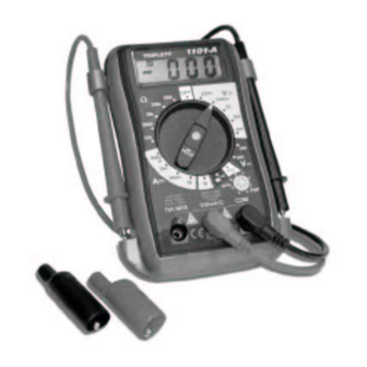
FRONT PANEL Backlit LCD Display Backlight and Hold button Rotary Function / Range Selector Switch Transistor Test Jack COM Jack: Common (black) jack for all measurements 10A Jack: Input for currents from 200mA to 10A V/Ω /mA / F Jack: Input for Voltage, Ohms, µA, mA, and Temperature... -
Page 13: Measurement Procedures
MEASUREMENT PROCEDURES DC Voltage Measurement: WARNING! If the magnitude of the voltage to be measured is unknown, always start by setting the meter to the highest range, and then to lower ranges, until a satisfactory reading is obtained. Do not rotate the RANGE switch with the input applied to the meter. If the input voltage is higher than 500VDC, or exceeds the limitations of a CAT I 600V measurement, do not attempt to measure! WARNING! - Page 14 probes, and rotate the RANGE switch to the next lower position. Reconnect the test probes, reapply power, and read the voltage on the LCD display. If the RANGE switch is already on the lowest position (i.e. 200mV DC), no greater measurement resolution can be obtained. AC Voltage Measurement: WARNING! If the magnitude of the voltage to be measured is unknown, always start...
- Page 15 7.2.5 If the displayed value is less than "200" (decimal point not shown), a more accurate reading may be obtained by setting the RANGE switch to a lower range. Remove power from the circuit, disconnect the test probes, and rotate the RANGE switch to the next lower position. Reconnect the test probes, reapply power, and read the voltage on the LCD display.
- Page 16 measure 10A, the current being tested exceeds the measurement capability of the meter and cannot be measured. 7.3.5 If the displayed value is less than "200" (decimal point not shown), a more accurate reading may be obtained by setting the RANGE switch to a lower range.
- Page 17 Continuity Beeper: WARNING! Do not apply voltage or current to the meter when it is set to the Diode Test / Continuity Beeper mode Connect the black test lead to the COM jack and the red test lead to 7.5.1 the V/Ω...
- Page 18 are connected in either direction to the diode, the diode is probably shorted. Note: The reading displayed on the LCD is not an accurate indication of the voltage drop of the device or circuit being measured. Temperature Test: WARNING! Do not apply voltage or current to the meter when it is set to the Temperature measurement mode.
-
Page 19: Backlight And Hold
20 seconds and then turn itself off. Hold: A Hold feature is incorporated into the 1101-A. It is a momentary Hold feature that only holds a reading as long as the associated button is kept depressed. Since the button that performs Hold is also the Backlight button, if the Hold feature is engaged for longer than 3 seconds, the Backlight will turn on. -
Page 20: Maintenance
MAINTENANCE Battery and Fuse Replacement: 9.1.1 On the back of the case, remove the rubber bumpers that cover the case screws. Remove the screws. 9.1.2 Gently open case, starting at the bottom where the screws were removed. 9.1.3 When the back of the case is removed, remove the depleted battery or damaged fuse, replace, and reassemble the meter. - Page 21 Annual calibration is not included in the warranty. Service: TRIPLETT PRODUCT RETURN INSTRUCTIONS In the unlikely event that you must return your Triplett equipment for repair, the following steps must be taken. 1) Call 1-800-TRIPLETT to obtain a Return Material Authorization (RMA) number from Customer Service.
-
Page 22: Limited Warranty
Triplett Corporation may have, including incidental or consequential damages. - Page 23 Some states (USA ONLY) do not allow the exclusion or limitation of incidental or consequential damages, so the above limitation or exclusion may not apply to you. No representative of Triplett Corporation or any other person is authorized to extend the liability of Triplett Corporation in connection with the sale of its products beyond the terms hereof.
Need help?
Do you have a question about the 1101-A and is the answer not in the manual?
Questions and answers