Table of Contents
Advertisement
Advertisement
Table of Contents

Related Manuals for Triplett 9065


Summary of Contents for Triplett 9065
- Page 1 9065 odel True RMS Data Logging MultiMeter Instruction Manual 84-910 12/15...
-
Page 2: Table Of Contents
Contents I. Introduction----------------------------------------------------------1 12. Temperature------------------------------------------------27 II.Included Items------------------------------------------------------1 13. LPF-----------------------------------------------------------28 Ill. Rules for Safe Operation---------------------------------------2 14. dBV-----------------------------------------------------------29 IV. Electrical Symbols-----------------------------------------------3 15. dBm----------------------------------------------------------29 V. Meter Structure----------------------------------------------------4 16. Maximum Value and Minimum Value----------------29 VI. LCD Display-------------------------------------------------------5 17. Relative Value Mode-------------------------------------30 VII. Keys, Rotary Switch and Input Terminals-----------------6 18. -
Page 3: Introduction
I. Introduction II. Included Items The Model 9065 is a 60000 count, or 4 5/6 digit, Open the package and the carrying case and inspect the handheld auto-ranging true RMS Digital Multimeter contents. Please check that all of the following items are (hereinafter referred to as “the meter’’). -
Page 4: Ill. Rules For Safe Operation
III. Rules for Safe Operation 1. Never use a damaged meter. Before using the meter, Please note the Warning symbol. Warnings indicate check the meter case for visible cracks or any missing plastic the conditions and actions which pose hazards to users or parts. -
Page 5: Electrical Symbols
If in doubt, contact it with a test lead of the same or higher grade of CAT Ill your distributor or Triplett Customer Service. 1000V/CAT IV 600V. 12. Do not store or use the meter in an environment with high... -
Page 6: Meter Structure
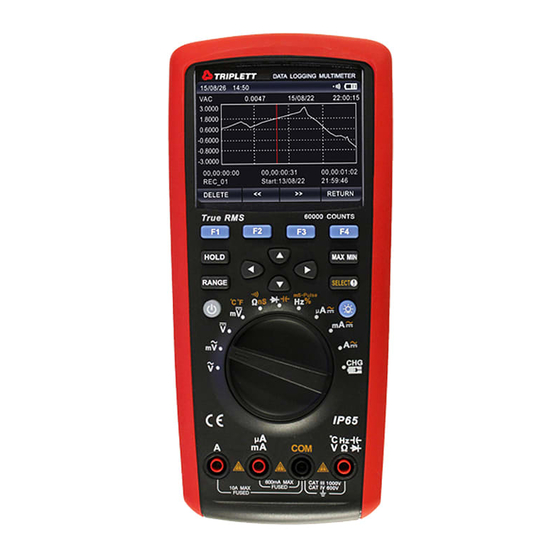
V. Meter Structure (see Figure 1) Case Function Keys Rotary Switch Input Terminals... -
Page 7: Lcd Display
V. LCD Display (see Figure 2) No. Function Description Label of Function Indicates auxiliary functions under current Keys measuring interface Simulation Bar Analog display of input signals Minus Sign Indicates negative reading Lightning Symbol Danger- High Voltage Time and Date Indicates the time and date set in internal clock Small... -
Page 8: Keys, Rotary Switch And Input Terminals
VII. Keys, Rotary Switch and Input Terminals (1) Keys The 14 keys on the meter are used to activate the alternate functions of the rotary switch, browse menus or control the me- ter power. The keys shown in Figure 3 are described in the following table. Function Turn on or turn off the power to the meter F1 F2 F3 F4 Select the sub-functions and modes indicated by the labels on the LCD screen. - Page 9 Figure 3 & 4 Knob Function Hz% mS-Pulse Measurement of frequency, duty cycle and pulse width µA Measurement of A in AC, DC and AC+DC Measurement of mA in AC, DC and AC+DC Measurement of ampere in AC, DC and AC+DC Battery is charging (3) Input Terminals Terminal...
-
Page 10: Technical Lndex
VIII. Technical Index 1. General Specifications The maximum voltage between any terminal and ground: 1000 V The fuse protection of mA or µA input terminals: 0. 8A H 1000V Fuse Type 6X32mm The fuse protection of the A input terminal: 10A H1000V Fuse Type 10X38mm Max. -
Page 11: Electrical Specifications
2. Electrical Specifications Accuracy: ±(% Reading + Digits), one-year calibration period. Ambient temperature: 23°C± 5°C; Ambient humidity: 75%RH; Temperature coefficient: 0.1x (Accuracy)/ °C (<18 °C or >28°C) 2. Electrical Specifications Range Resolution Accuracy Tolerance: ± (% Reading + Digits) 45~1kHz 1k~10kHz 10k~20kHz 20k~100kHz... - Page 12 (2) DC Voltage Range Resolution Accuracy Tolerance: ± (% Reading + Digits) 60mV 0.001mV ± (0.025%+20) 600mV 0.01mV 0.0001V ± (0.025%+5) 0.001V 600V 0.01V ± (0.03%+5) 1000V 0.1V • Input impedance: About 10MΩ • Overload protection: 1000V • Display: True RMS value for 10% to 100% of the range. (3) AC Voltage + DC Voltage Range Resolution...
- Page 13 • Input impedance: About 10MΩ • Overload protection: 1000V • Display: True RMS value for 10% to 100% of the range. (4) AC Current Range Resolution Accuracy Tolerance: ± (% Reading + Digits) 45~1kHz 1k~10kHz 600µA 0.01µA +(0.6%+40) +(1.2%+40) 45~1kHz 1k~10kHz 6000µA 0.1µA...
- Page 14 (5) DC Current Range Resolution Accuracy Tolerance: ± (% Reading + Digits) 600µA 0.01 µA +(0.08%+20) 6000µA 0.1 µA + (0.08%+10) 60mA 0.001 mA + (0.08%+20) 600mA 0.01 mA +(0.15%+10) 0.001A +(0.5%+10) • Overload protection: µAmA range: 0.8A H 1000V Fuse Type ɸ 6x32 mm 10 A range: 10A H 1000V Fuse Type ɸ...
- Page 15 • Display: True RMS value for 10% to 100% of the range. • Overload protection: µAmA range: 0.8A H 1000V Fuse Type ɸ 6x32 mm 10 A range: 10A H 1000V Fuse Type ɸ 10x38mm • Switch on for 30 seconds and suspend measurement for 10 minutes for 20A. Not specified for over 10A. (7) Resistance Range Resolution...
- Page 16 (9) Capacitance Range Resolution Accuracy Tolerance: ± (% Reading + Digits) 0.001nF +(3%+10) 60nF 0.01nF +(2.5%+5) 600nF 0.1nF 6µF 0.001µF +(2%+5) 60µF 0.01µF 600µF 0.1µF 1µF +(5%+5) 60mF 10µF Not specified • Overload protection: 1000V • Display digits: 6000 (10) Temperature Range Resolution Accuracy...
- Page 17 (11) Frequency Range Resolution Accuracy 60Hz 0.001 Hz +(0.02%+8) 600Hz 0.01 Hz 6kHz 0.0001kHz 60kHz 0.001kHz +(0.01%+5) 600kHz 0.01kHz 6MHz 0.0001MHz 60MHz 0.001MHz • Overload protection: 1000V • Display digits: 6000 (12) Duty Cycle Range Resolution Accuracy Tolerance: ± (% Reading + Digits) 10%~90%(10Hz~2kHz) 0.01% +(1.2%+30)
- Page 18 (14) Continuity Test Range Resolution Remark Open circuit voltage is around 3V. When the buzzer is set for Short Circuit warning; If the impedance tested is less than 10Ω, the buzzer continuously sounds. If the impedance tested is 0.01Ω greater than 50Ω, the buzzer does not sound. When the buzzer is set for Open Circuit warning;...
-
Page 19: Measurement Operation
IX. Measurement Operation 1. Meter Power Control 1) To manually power up and power down the meter: When the meter is off, long press to start the meter. When the meter is on, long press to shut it off. The meter cannot be powered off when charging. 2) Indicators for Battery Level: The meter is powered by a rechargeable lithium battery. -
Page 20: Meter Settings
2. Meter Settings Press the function key labelled, SETUP to access the general settings for the meter. Press the cursor keys navigate through the settings menu. 1) Keypad Tone This function enables or disables sound when a button is pressed. The beeper symbol in the upper right corner indicates that sound is enabled. - Page 21 6) More Settings With “More Settings” highlighted in the SETUP Menu, press the function key “ENTER” to: Set the language of the Help Menu, Format Memory, Reset the meter settings, or check the model number, serial number and available memory space. Press the cursor keys to select between the following menu items.
-
Page 22: Ac Voltage
3. AC Voltage will have decreased accuracy. 1) Insert the red test lead into the V terminal and the black test lead into the COM terminal. 2) Set the rotary switch to V or mV as shown in Figure 5. Connect the test leads to the power or load under test in parallel. -
Page 23: Ac And Dc Current
4) Press the function key labelled, “MENU” to access Attention: additional features for measuring AC or DC current. • Do not input a voltage higher than 1000V. Higher voltage Press the cursor keys to select menu items. may be measured but it may damage the meter. The red highlighting indicates the selected item. -
Page 25: Resistance
6. Resistance • When measuring a resistance >1MΩ, the readings require 1) Insert the red test lead into the Ω terminal and the black a few seconds to stabilize. This is normal for high resis test lead into the COM terminal. tance measurements. -
Page 26: Conductance
7. Conductance 3) Directly read the measured capacitance value on the 1) Insert the red test lead into the Ω terminal and the black display. test lead into the COM terminal. Attention: 2) Set the rotary switch to the measurement Ω nS •... -
Page 27: Continuity Test
When the buzzer is set for Short Circuit warning; If the impedance tested is less than 10Ω, the buzzer continuously sounds. If the impedance tested is greater than 50Ω, the buzzer does not sound. When the buzzer is set for Open Circuit warning; If the impedance tested is greater than 50Ω, the buzzer continu- ously sounds. - Page 28 2) Set the rotary switch to the position. The meter will default to Diode measurement. Connect the test leads to both ends of the diode as shown in Figure 10. Directly read the approximate forward PN junction voltage of the measured diode on the display.
-
Page 29: Frequency/Duty Cycle Measurement/Pulse Width-27
11. Frequency/Duty Cycle Measurement /Pulse Attention: Width • Simulation bar displays the frequency of the measured signal for duty cycle and pulse width. 1) Insert the red test lead into the V terminal and the black • After completing all measurements, disconnect the test lead into the COM terminal. -
Page 30: Lpf
13. LPF Measurement Attention: • If the ambient temperature for the meter is outside the 1) Insert the red test lead into the V terminal and the black range of 18 °C to 28 °C, it may cause measurement errors. test lead into the COM terminal. -
Page 31: Dbv
• In the LPF measuring mode, the meter will turn to manual 2) Set the rotary switch to V. Connect the test leads to the mode. Press the RANGE key to select a range. When the power or load to be tested in parallel as shown in low-pass filter is enabled, automatic range is unavailable. -
Page 32: Relative Value Mode
Press the function key labelled, “EXIT” to exit Max Min Mode. 1) Pass Mode • INNER(Low Value ≤ Input Value ≤ High Value) 17. Relative Value Mode • OUTER (Input Value < Low Value OR Input Value >High Value) Press the function key labelled, “MENU” to enter the •... -
Page 33: Recording Measurement Data
20. Recording Measurement Data Press (UP) or (DOWN) to edit the three following settings. • Edit Name Press the function key labelled, “SAVE” to enter the menu In the Record Menu with “Edit Name” highlighted, press the for saving, recording or viewing data. Press the cursor keys “EDIT”... - Page 34 When Recording, the characters “REC” show on the display 5) View Record with a flashing red dot, as shown in Figure 13. The relevant In the Save Menu with “View Record” highlighted, press the display information is shown in the following table. “View”...
-
Page 35: Communication
While viewing a Record, press the “PREV” function key to Viewing the trend chart: Press or hold the F2 key to move display the previous record. Press the “NEXT” function key the cursor left. Press or hold the F3 key to move the cur- to display the next record. -
Page 36: Maintenance And Repair
USB Communication 5) When the meter needs to be verified or repaired, qualified service personnel or a designated maintenance department Turn on communication via settings (see detailed operations are required to repair it. in the section 2. Meter Settings). The symbol will 2. -
Page 37: Replacing Fuses
A “Charge 5) Reinstall the battery cover and then turn the screw complete” message will display when fully charged. clockwise to tighten the battery cover. Attention: You must use the power adapter specified by Triplett. -
Page 38: Warranty
Triplett or any other person is authorized to of (3) three years from the date of purchase. extend the liability of Triplett in connection with the sale of its products beyond the terms hereof. This warranty does not apply to any of our products which... -
Page 39: Notes
XII. Notes... - Page 40 Model 9065 84-910 Part Number: 9065 10/15 Made in China...
Need help?
Do you have a question about the 9065 and is the answer not in the manual?
Questions and answers