Advertisement
Quick Links
Advertisement

Related Manuals for Triplett 9007-A


Summary of Contents for Triplett 9007-A
- Page 1 84-909 1/15 1.800.561.8187 information@itm.com www. .com...
- Page 2 10. Accessories 5. Specifications 1: INTRODUCTION The Triplett 9007-A is a ruggedized 3 ½ digit (2000 count) high performance precision digital multimeter with a large backlit high contrast LCD display. Its offering of measurement features includes AC and DC Voltage and Current, Resistance, Continuity, Diode Test, Temperature, Frequency and Capacitance.
- Page 3 2: SAFETY RULES & WARNINGS Read all instructions in this manual before using this meter. Failure to do so may result in damage to the meter or injury to the user. Prior to using the meter in any situation which could result in injury to the user, in order to verify that the meter is functional and producing a valid reading, test the meter on a circuit(s) known to have...
- Page 4 Follow the recommendations of any Trade Organizations or Regulatory Agencies whose scope encompasses the use of this meter. Failure to do so may result in damage to the meter or injury to the user. Do not open this meter for maintenance without first disconnecting the test leads from all external circuitry.
- Page 5 meter or injury to the user. 2.10 Make sure test leads are properly inserted and seated in the meter’s input jacks. A loose test lead may cause the user to believe that no hazard exists, when in fact, dangerous voltages or currents may be present. Failure to observe this precaution may result in damage to the meter or injury to the user.
- Page 6 the test leads in incorrect jacks can damage the meter and/or injure the user. 2.14 Do not exceed the maximum voltage or current limitations of the meter (see product specifications). Doing so may damage the meter and/or injure the user. 2.15 Do not apply voltage or current to the input of the meter when it is set to any of the Ohms...
- Page 7 user. 2.19 Replace fuses only with exact or equivalent fuses. Do not “bridge” fuses out of circuit. Failure to observe this precaution may result in damage to the meter or injury to the user. 2.20 Do not apply voltages to the input of the meter which are elevated above the earth ground potential by more than 600V AC/DC.
- Page 8 this precaution may result in damage to the meter or injury to the user. 2.24 Do not use this meter to make measurements in adverse environments such as rain, snow, fog, or locations with steam, explosive gases or dusts. Doing so may damage the meter and/or injure the user.
- Page 9 this precaution may result in damage to the meter or injury to the user. 2.28 Do not modify the meter. Changing the design may make the meter unsafe and may result in injury to the user. 2.29 Use caution when attempting to evaluate if a dangerous voltage is present.
- Page 10 2.32 Use caution when measuring circuits containing capacitors. Capacitors can store dangerous or lethal levels of electricity, even when the circuitry which they are in has been disconnected from its power source. Some capacitors could source enough energy to damage the meter and/or injure the user. 2.33 Do not use the meter if there is evidence of chemical leakage from the battery.
- Page 11 injury to the user. 2.36 If there is any doubt about the condition of the meter (i.e. safe vs unsafe), remove the meter from service and secure it in a location that will prevent its unintentional use. Failure to observe this precaution may result in damage to the meter or injury to the user.
- Page 12 low side of a power circuit first. Never clamp onto a hot wire first, (usually red, black, or blue in AC wiring circuits.) If you clamp onto a hot wire first, and touch the other probe, you could receive a shock. Failure to observe this precaution may result in damage to the meter or injury to the user.
- Page 13 the hazards present. For example, the meter may indicate a low voltage when high voltages are actually present. Failure to observe this precaution may result in damage to the meter or injury to the user. 2.44 Avoid usage near strong RF fields (radio or television transmitters, walkie talkies, cellular phones, etc.).The meter may display readings that are in error, causing the user to...
- Page 14 Discharging these capacitors can be dangerous unless an approved method is used. Failure to observe this precaution may result in damage to the meter or injury to the user. 1.800.561.8187 information@itm.com www. .com...
- Page 15 3: INTERNATIONAL SYMBOLS The following International Symbols may be used in this manual and on the case of the meter to identify, caution, or warn the user of important product limitations or important operational procedures that must be followed to ensure safe usage of the product.
- Page 16 4: PRODUCT FEATURES 4.1 30 Measurement Ranges 4.2 Huge 1.4” tall High Contrast LCD display 4.3 White LCD Backlight allows viewing in poorly lit areas 4.4 3 1/2 digit resolution (2000 counts) 4.5 Protective shock absorbing overmolded shell with built in stand and test lead holders 4.6 Diode Test 4.7 Continuity Beeper Temperature Test...
- Page 17 7.1 x 3.2 x 2.1 inches (L x W x H) 5.9 Weight (w battery) ………….Approx. 360 grams, 0.79 lbs. 5.10 Battery: ....…..1 standard 9 volt alkaline battery NEDA 1604, Triplett Part No. 37-48 5.11 Battery Life: ..…....Typically 200 hours 5.12 Fuses: ....…....0.2A / 250 volt FAST, 5 x 20mm fuse, for mA ranges.
- Page 18 5: SPECIFICATIONS CONT. 5.13 Insulation: ....Double Insulated (Protection Class II) 5.14 Pollution Degree ….2 5.15 Approvals: ....IEC 1010-1 (EN61010-1) Overvoltage Category (Installation Category) Category I to 600 volts DC, 600 volts AC Category II to 600 volts DC, 600 volts AC Category III to 600 volts DC, 600 volts AC CE: EMC, LVD Note: a) The following accuracy specifications are valid at 23...
- Page 19 DC Voltage Range Resolution Accuracy 200.0mV 0.1mV ± (0.5% rdg + 2 digit) 2.000V 20.00V 10mV 200.0V 100mV ± (0.8% rdg + 2 dgt) 600V Input Impedance: All ranges are 10MΩ Overload Protection: 200mV Range: 250V AC/DC rms. s. s s Other VDC ranges: 600VDC, 600VAC rms AC Voltage Range...
- Page 20 DC Current Accuracy Range Resolution ±(1.0% rdg + 3 digits) 2.000mA 1μA 200.0mA μA ±(1.5% rdg + 3 digits) 10.00A ±(2.5% rdg + 10 digits) 10mA Overload Protection: 0.2A / 250V fuse (below 200mA range) 10A /600V fuse (10A range) Limit measurement time on 10A range to 30 seconds for inputs over 10A.
- Page 21 Resistance Accuracy Resolution Range ± (1.0% rdg + 4 digits) after subtracting any 200.0 residual resistance noted when test leads are shorted. 2.000K ± (1.0% rdg + 2 digits) 20.00K 200.0K ± (1.2% rdg + 2 digits) 2.000M 20.00M ± (2.0% rdg + 5 digits) Overload Protection: All ranges 250V DC or AC RMS.
- Page 22 Temperature Range Resolution Accuracy C~+760 ± (3% of rdg ± 5 F~+1400 ± (3% of rdg ± 9 Sensor: Type K Thermocouple Overload protection: 250V DC or AC RMS. Diode Test and Continuity Beeper Range Display Notes Test current: 1mA typical Actual Open circuit voltage: 2.8V DC diode...
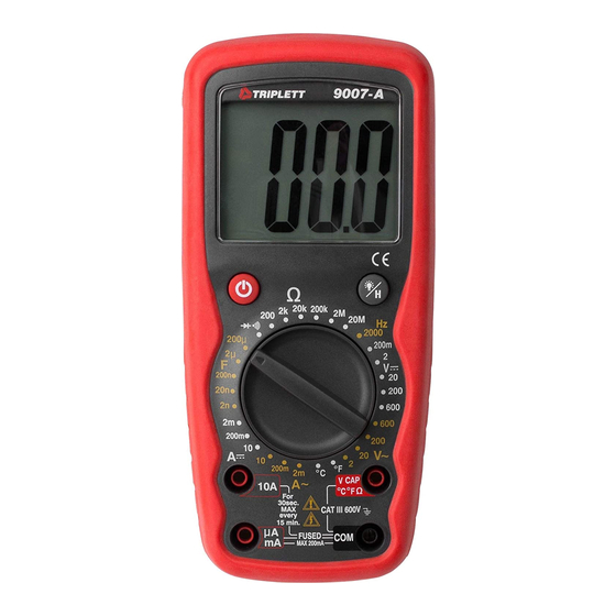
- Page 23 6: FRONT PANEL Large 2000 count Liquid Crystal Display Power button: turns the meter ON or OFF. . Function Switch 10A (positive) input jack for 10A DC or AC measurements mA input jack for mA DC or AC measurements Backlight and DATA HOLD pushbutton. .
- Page 24 LCD Backlight / DATA HOLD The 9007-A incorporates a convenient LCD Backlight. The Backlight provides illumination for the LCD in dimly lit conditions. When the...
- Page 25 Power Button and Auto Power Off: Turn on the 9007-A by pressing the yellow power button . Press it again to turn the meter off. The 9007-A has Auto Power Off. This feature automatically turns the meter off 10 to 15 minutes after it was turned on..
- Page 26 7.3.2 Set the RANGE switch to a V position. If the magnitude of the voltage is unknown, set the RANGE switch to the highest V position. If the input voltage is higher than the previously stated limits, do not attempt to measure! 7.3.3 Connect the test probes to circuit being measured.
- Page 27 measurement resolution can be obtained. 7.4 AC Voltage Measurement: WARNING! If the magnitude of the voltage to be measured is unknown, always start by setting the meter to the highest range, and then to lower ranges, until a satisfactory reading is obtained. Do not rotate the RANGE switch with the input applied to the meter.
- Page 28 7.4.4 If the display indicates overrange, i.e. “1- - -”, disconnect the test probes from the circuit and rotate the RANGE switch to the next higher position. Reconnect the test probes to the circuit LCD display. If the RANGE switch is already at the highest position (i.e.
- Page 29 7.5 DC Current Measurement: WARNING! If the magnitude of the current to be measured is unknown, always start by setting the meter to the highest range, and then to lower ranges, until a satisfactory reading is obtained. Do not rotate the RANGE switch with the input applied to the meter. If the input current is higher than 10A, do not attempt to measure! Use caution when measuring current in a circuit with voltages above 50 VDC.
- Page 30 7.5.3 If the red test lead is inserted into the uA mA jack, set the RANGE switch to the 200m A position. Connect the test leads IN SERIES with the circuit to be measured. Read the value of the current on the LCD.
- Page 31 7.6 AC Current Measurement: WARNING! If the magnitude of the current to be measured is unknown, always start by setting the meter to the highest range, and then to lower ranges, until a satisfactory reading is obtained. Do not rotate the RANGE switch with the input applied to the meter. If the input current is higher than 10A, do not attempt to measure! Use caution when measuring current in a circuit with voltages above 30 VAC.
- Page 32 7.6.3 If the red test lead is inserted into the uA mA jack, set the RANGE switch to the 200m A~ position. Connect the test leads IN SERIES with the circuit to be measured. Read the value of the current on the LCD.
- Page 33 7.7 Resistance Measurement: WARNING! Do not apply voltage or current to the meter when it is set to any of the “ ” ranges. 7.7.1 Connect the black test lead to the COM jack, and the red test lead to the input jack indicated as on the “Front Panel”...
- Page 34 7.7.5 If the displayed value is less than “200” (decimal point not shown), a more accurate reading may be obtained by setting the RANGE switch to a lower range. Rotate the RANGE switch to the next lower position and observe the reading on the LCD display. If the RANGE switch is already on the lowest position (i.e.
- Page 35 7.8 Continuity Beeper: WARNING! Do not apply voltage or current to the meter when it is set to the Diode Test / Continuity Beeper “ ” range. 7.8.1 Connect the black test lead to the COM jack and the red test lead to the input jack indicated as on the “Front Panel”...
- Page 36 7.9 Diode Test: WARNING! Do not apply voltage or current to the meter when it is set to the Diode Test / Continuity Beeper “ ” range 7.9.1 Connect the black test lead to the COM jack and the red test lead to the input jack indicated as on the “Front Panel”...
- Page 37 7.10 Measuring Capacitance: WARNING! Do not apply voltage or current to the meter when it is set to the Capacitance “F ” ranges. Do not connect a charged capacitor to the meter. Doing so may damage the meter or injure the user. 7.10.1 Connect the black test lead to the COM jack and the red test lead to the input jack indicated as on the...
- Page 38 7.10.5 If the displayed value is less than “200” (decimal point not shown), a more accurate reading may be obtained by setting the RANGE switch to a lower range. Rotate the RANGE switch to the next lower position and observe the reading on the LCD display. If the RANGE switch is already on the lowest position (i.e.
- Page 39 7.11 TEMPERATURE MEASUREMENTS: WARNING! To avoid electric shock, disconnect both test probes from any source of voltage before making a temperature measurement. 7.11.1 If you wish to measure temperature in F, set the function switch to the F range. If you wish to measure temperature in C, set the / Button to the...
- Page 40 2000Hz. 8: TEST LEAD HOLDERS STAND, and HANGER Test Lead Holders are provided on the back of the 9007-A. The test leads may be snapped into the back of the meter for storage, or one or both leads may be snapped into the holders with the tip protruding, forming a handy ‘meter with probe’...
- Page 41 9: MAINTENANCE Your Triplett Model 9007-A DMM is a precision measuring instrument and, when used as described in this manual, should not require maintenance. However, periodic calibration of the meter will insure that it is accurate and performing in accordance with its design specifications.
- Page 42 9.1.3 Remove the 9 volt battery and, observing proper polarity, replace with a fresh battery (PN 37-48). 9.1.4 Reassemble battery compartment cover. Reinstall screws. 9.1.5 Verify that the meter operates properly before using it to make measurements. 9.2 Replacing Fuses: 9.2.1 Remove the test leads from the meter.
- Page 43 9.2.5 Reassemble case of meter. Reinstall screws. 9.2.6 Verify that the meter operates properly before using it to make measurements. 1.800.561.8187 information@itm.com www. .com...
- Page 44 10: ACCESSORIES 10.1 The Triplett Model 9007-A package contains the following items: - The Model 9007-A DMM - Test leads for the 9007-A (Triplett PN 79-127) - “K-Type” Temperature Probe Instruction Manual (Triplett PN 84-909) 10.2 Several different carrying cases may be used for the 9007-A.
- Page 45 WARRANTY Triplett / Byte Brothers extends the following warranty to the original purchaser of these goods for use. Triplett warrants to the original purchaser for use that the products sold by it will be free from defects in workmanship and material for a period of (3) three years from the date of purchase.
- Page 46 Some states (USA ONLY) do not allow the exclusion or limitation of incidental or consequential damages, so the above limitation or exclusion may not apply to you No representative of Triplett / Byte Brothers or any other person is authorized to extend the liability of Triplett in connection with the sale of its products beyond the terms hereof.
Need help?
Do you have a question about the 9007-A and is the answer not in the manual?
Questions and answers