Table of Contents
Advertisement
Advertisement
Table of Contents

Subscribe to Our Youtube Channel
Related Manuals for Triplett 9007


Summary of Contents for Triplett 9007
-
Page 1: Digital Multimeter
99 Washington Street Melrose, MA 02176 Phone 781-665-1400 Toll Free 1-800-517-8431 TRIPLETT Model 9007 Digital Multimeter Instruction Manual Test Equipment Depot - 800.517.8431 - 99 Washington Street Melrose, MA 02176 Visit us at www.TestEquipmentDepot.com TestEquipmentDepot.com... -
Page 2: Table Of Contents
10. Accessories 5. Specifications 1: INTRODUCTION The Triplett 9007 is a ruggedized 3 ½ digit (2000 count) high perfor- mance precision digital multimeter with a large backlit high contrast LCD display. Its offering of measurement features includes AC and DC Voltage and Current, Resistance, Continuity, Diode Test, and Capaci- tance. - Page 3 2: SAFETY RULES & WARNINGS Read all instructions in this manual before using this meter. Failure to do so may result in damage to the meter or injury to the user. Prior to using the meter in any situation which could result in injury to the user, in order to verify that the meter is functional and producing a valid reading, test the meter on a circuit(s) known to have potentials equivalent to the...
- Page 4 Follow the recommendations of any Trade Organizations or Regulatory Agencies whose scope encompasses the use of this meter. Failure to do so may result in damage to the meter or injury to the user. Do not open this meter for maintenance without first disconnecting the test leads from all external circuitry.
- Page 5 precaution may result in damage to the meter or injury to the user. 2.10 Make sure test leads are properly inserted and seated in the meter’s input jacks. A loose test lead may cause the user to believe that no hazard exists, when in fact, dangerous voltages or currents may be present.
- Page 6 2.14 Do not exceed the maximum voltage or current limitations of the meter (see product specifications). Doing so may damage the meter and/or injure the user. 2.15 Do not apply voltage or current to the input of the meter when it is set to any of the Ohms Ω ranges. Doing so may damage the meter and/or injure the user.
- Page 7 2.20 Do not apply voltages to the input of the meter which are elevated above the earth ground potential by more than 600V AC/DC. Doing so may damage the meter and/or injure the user. 2.21 Do not continue to use meter when the “low battery” symbol is displayed.
- Page 8 2.25 Do not use meter in condensing atmospheres. That is, do not use meter in conditions where ambient temperature and humidity could cause condensation of water inside of meter. Doing so may cause injury to the user. 2.26 Do not use the meter if either the meter or the test leads are wet, either from exposure to the weather, or after cleaning the case of the meter.
- Page 9 inserted into a household AC wall outlet. 2.30 Do not touch the metallic portion of one test lead if the other test lead is connected to a live circuit. The current from the live circuit may pass through the meter and appear on the unconnected test lead.
- Page 10 2.34 Do not use this meter to measure current in circuits whose open circuit voltage exceeds 250V AC/DC. The meter’s fuses are rated at 250V max. Failure to observe this precaution may result in damage to the meter or injury to the user. 2.35 When you use the meter to check a high-voltage circuit, do not try to connect both test leads at once.
- Page 11 2.37 Do not use the meter if it does not appear to work correctly on all ranges and in all modes. Failure to observe this precaution may result in damage to the meter or injury to the user. 2.38 Do not use the meter if it has undergone long-term storage under unfavorable conditions.
- Page 12 2.41 To avoid damage to the meter and possible user injury, disconnect test leads from test points before changing the function/range. Failure to observe this precaution may result in damage to the meter or injury to the user. 2.42 Avoid usage near strong magnetic fields (magnets, loudspeakers, transformers, motors, coils, relays, contactors, electromagnets, etc.).
- Page 13 2.44 Avoid usage near strong RF fields (radio or television transmitters, walkie talkies, cellular phones, etc.). The meter may display readings that are in error, causing the user to misinterpret the hazards present. For example, the meter may indicate a low voltage when high voltages are actually present.
-
Page 14: International Symbols
3: INTERNATIONAL SYMBOLS The following International Symbols may be used in this manual and on the case of the meter to identify, caution, or warn the user of important product limitations or important operational procedures that must be followed to ensure safe usage of the product. Ground Low Battery See Instruction Manual... -
Page 15: Product Features
4: PRODUCT FEATURES 31 Measurement Ranges Huge 1.4” tall High Contrast LCD display White LCD Backlight allows viewing in poorly lit areas 3 1/2 digit resolution (2000 counts) Protective shock absorbing overmolded shell with built in stand and test lead holders Diode Test Continuity Beeper Capacitance Test... -
Page 16: Specifications
7 x 3.2 x 2.2 inches (L x W x H) 5.9 Weight (w battery) ………..Approx 400 grams, 0.88 lbs. 5.10 Battery: ....…..1 standard 9 volt alkaline battery NEDA 1604, Triplett Part No. 37-48 5.11 Battery Life: ..…....Typically 200 hours 5.12 Fuses: ....…....0.2A / 250 volt FAST, 5 x 20mm fuse, for mA ranges. - Page 17 5: SPECIFICATIONS CONT. 20A / 250 volt FAST, 6 x 25mm, for 20A range. Triplett Part No. 3207-134 5.13 Insulation: ......Double Insulated (Protection Class II) 5.14 Pollution Degree ………….2 5.15 Approvals: ......IEC 1010-1 (EN61010-1) Overvoltage Category (Installation Category) Category I to 1000 volts DC,...
- Page 18 Note: a) The following accuracy specifications are valid at 23 degrees C, +/- 5 degrees C, Relative Humidity less than 75% b) The specifications are in the form “ +/- (x % of reading + LSD)” where LSD is “Least Significant Digit”. DC Voltage Range Resolution...
- Page 19 AC Voltage Range Accuracy Resolution ± (1.0% rdg + 5 digits) 200.0mV 0.1mV 2.000V ± (1.0% rdg + 3 digits) 20.00V 10mV 200.0V 100mV ± (1.2% rdg + 5 digits) 700V Input Impedance: All ranges are 10MΩ Frequency: 50Hz to 400Hz Overload Protection: 200mV Range: 250V AC/DC rms.
- Page 20 AC Current Range Resolution Accuracy 2.000mA 1µA ± (1.2% rdg + 3 digits) 200.0mA 100µA ± (2.0% rdg + 3 digits) 20.00A 10mA ± (3% rdg + 10 digits) Overload Protection: 0.2A / 250V fuse (below 200mA range) 20A /250V fuse (20A range) Limit measurement time on 20A range to 30 seconds for inputs over 10A.
- Page 21 Overload Protection: All ranges 250V DC or AC RMS. * On 200M Ohm range, it is normal for the meter to display 10 LSD with the test leads shorted together. To obtain an accurate reading, subtract 10 LSD from the displayed value. Capacitance Accuracy Resolution...
-
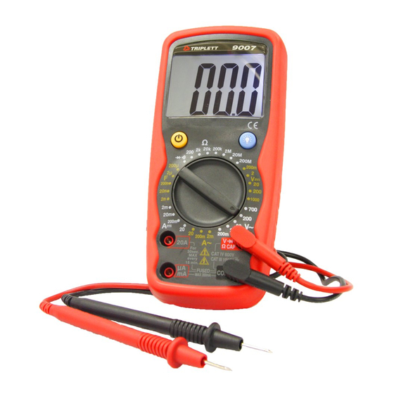
Page 22: Front Panel
6: FRONT PANEL 1. LCD Display 2. Power Button 3. Function Switch 4. 20A Input Jack 5. uA and mA Input Jack 6. COM Input Jack 7. Volt, Ohm, Capacitance, Diode Test, and Continuity Input Jack 8. Backlight Button Page 21 Test Equipment Depot - 800.517.8431 - 99 Washington Street Melrose, MA 02176 TestEquipmentDepot.com... -
Page 23: Measurement Procedures
Turn on the 9007 by pressing the yellow power button Press it again to turn the meter off. The 9007 has Auto Power Off. This feature automatically turns the meter off 10 to 15 minutes after it was turned on..thereby extending battery life. - Page 24 7.3 DC Voltage Measurement: WARNING! If the magnitude of the voltage to be measured is unknown, always start by setting the meter to the highest range, and then to lower ranges, until a satisfactory reading is obtained. Do not rotate the RANGE switch with the input applied to the meter. If the input voltage is higher than 1000VDC (CAT I, CAT II, or CAT III), or 600V DC (CAT IV), do not attempt to measure! Use Caution when measuring voltages above 50V DC.
- Page 25 7.3.4 If the display indicates overrange, i.e. “1- - -”, disconnect the test probes from the circuit and rotate the RANGE switch to the next higher position. Reconnect the test probes to the circuit and observe the reading on the LCD display. If the RANGE switch is already at the highest position (i.e.
- Page 26 7.4 AC Voltage Measurement: WARNING! If the magnitude of the voltage to be measured is unknown, always start by setting the meter to the highest range, and then to lower ranges, until a satisfactory reading is obtained. Do not rotate the RANGE switch with the input applied to the meter. If the input voltage is higher than 700VAC (CAT I, CAT II, CAT III), or 600VAC (CAT IV), do not attempt to measure! Use Caution when measuring voltages above 30V AC.
- Page 27 7.4.4 If the display indicates overrange, i.e. “1- - -”, disconnect the test probes from the circuit and rotate the RANGE switch to the next higher position. Reconnect the test probes to the circuit LCD display. If the RANGE switch is already at the highest position (i.e.
- Page 28 7.5 DC Current Measurement: WARNING! If the magnitude of the current to be measured is unknown, always start by setting the meter to the highest range, and then to lower ranges, until a satisfactory reading is obtained. Do not rotate the RANGE switch with the input applied to the meter. If the input current is higher than 20A, do not attempt to measure! Use caution when measuring current in a circuit with voltages above 50 VDC.
- Page 29 7.5.3 If the red test lead is inserted into the uA mA jack, set the RANGE switch to the 200m A position. Connect the test leads IN SERIES with the circuit to be measured. Read the value of the current on the LCD. 7.5.4 If the display indicates overrange, i.e.
- Page 30 7.6 AC Current Measurement: WARNING! If the magnitude of the current to be measured is unknown, always start by setting the meter to the highest range, and then to lower ranges, until a satisfactory reading is obtained. Do not rotate the RANGE switch with the input applied to the meter. If the input current is higher than 20A, do not attempt to measure! Use caution when measuring current in a circuit with voltages above 30 VAC.
- Page 31 7.6.3 If the red test lead is inserted into the uA mA jack, set the RANGE switch to the 200m A~ position. Connect the test leads IN SERIES with the circuit to be measured. Read the value of the current on the LCD. 7.6.4 If the display indicates overrange, i.e.
-
Page 32: Resistance Measurement
7.7 Resistance Measurement: WARNING! Do not apply voltage or current to the meter when it is set to any of the “ Ω ” ranges. 7.7.1 Connect the black test lead to the COM jack, and the red test lead to the VOLT / DIODE / OHM / CAP “V Ω... - Page 33 7.7.5 If the displayed value is less than “200” (decimal point not shown), a more accurate reading may be obtained by setting the RANGE switch to a lower range. Rotate the RANGE switch to the next lower position and observe the reading on the LCD display.
- Page 34 7.8 Continuity Beeper: WARNING! Do not apply voltage or current to the meter when it is set to the Diode Test / Continuity Beeper “ ” range. 7.8.1 Connect the black test lead to the COM jack and the red test lead to the VOLT / DIODE / OHM / CAP “V Ω...
- Page 35 7.9 Diode Test: WARNING! Do not apply voltage or current to the meter when it is set to the Diode Test / Continuity Beeper “ ” range 7.9.1 Connect the black test lead to the COM jack and the red test lead to the VOLT / DIODE / OHM / CAP “V Ω...
-
Page 36: Measuring Capacitance
7.10 Measuring Capacitance: WARNING! Do not apply voltage or current to the meter when it is set to the Capacitance “F ” ranges. Do not connect a charged capacitor to the meter. Doing so may damage the meter or injure the user. 7.10.1 Connect the black test lead to the COM jack and the red test lead to the VOLT / DIODE / OHM / CAP “V Ω... - Page 37 7.10.5 If the displayed value is less than “200” (decimal point not shown), a more accurate reading may be obtained by setting the RANGE switch to a lower range. Rotate the RANGE switch to the next lower position and observe the reading on the LCD display.
- Page 38 8: TEST LEAD HOLDERS STAND, and HANGER Test Lead Holders are provided on the back of the 9007. The test leads may be snapped into the back of the meter for storage, or one or both leads may be snapped into the holders with the tip protruding, forming a handy ‘meter with probe’...
-
Page 39: Maintenance
9: MAINTENANCE Your Triplett Model 9007 DMM is a precision measuring instrument and, when used as described in this manual, should not require maintenance. However, periodic calibration of the meter will insure that it is accurate and performing in accordance with its design specifications. - Page 40 9.1 Replacing Battery: 9.1.1 Remove the test leads from the meter. 9.1.2 Remove 1 screw from the top of the battery compartment cover. Flip the Stand out and remove the screw from the bottom of the battery compartment cover. The cover is sealed and may fit tightly.
- Page 41 9.2.3 Open the meter case by wiggling the back to separate it from the front. Set the back of the case to one side. 9.2.4 Locate the defective fuse and replace with the exact or equivalent type. See meter specifications. 9.2.5 Reassemble case of meter.
-
Page 42: Accessories
10.1.2 Test leads for the 9007 (Triplett PN 79-808) 10.1.3 Instruction Manual (Triplett PN 84-885) 10.2 Several different carrying cases may be used for the 9007. Contact a Triplett representative to obtain help with determining which case will suit your needs. - Page 43 Triplett Product Return Instructions In the unlikely event that you must return your Triplett equipment for repair, the following steps must be taken. 1) Call 1-800-TRIPLETT to obtain a Return Material Authorization (RMA) number from Customer Service. 2) Enclose a copy of the original sales receipt showing date of purchase.
- Page 44 Triplett Three Year Limited Warranty Triplett warrants instruments and test equipment manufactured by it to be free from defective material or workmanship and agrees to repair or replace such products which, under normal use and service, disclose the defect to be the fault of our manufacturing, with no charge within three years of the date of original purchase for parts and labor.
- Page 45 Triplett may have, including incidental or consequential damages.
- Page 46 Triplett Three Year Limited Warranty Triplett reserves the right to discontinue models at any time, or change specifications, price or design, without notice and without incurring any obligation. This warranty gives you specific legal rights, and you may have other rights which vary from state to state.
- Page 47 Page 46 Test Equipment Depot - 800.517.8431 - 99 Washington Street Melrose, MA 02176 TestEquipmentDepot.com...
- Page 48 Test Equipment Depot - 800.517.8431 - 99 Washington Street Melrose, MA 02176 TestEquipmentDepot.com...
Need help?
Do you have a question about the 9007 and is the answer not in the manual?
Questions and answers