
Subscribe to Our Youtube Channel
Related Manuals for SCHUNK CRT


Summary of Contents for SCHUNK CRT
- Page 1 Translation of Original Operating Manual Assembly and Operating Manual Compliant Reciprocating Tool...
- Page 2 Imprint Imprint Copyright: This manual is protected by copyright. The author is SCHUNK GmbH & Co. KG. All rights reserved. Technical changes: We reserve the right to make alterations for the purpose of technical improvement. Document number: 1453513 Version: 02.00 | 12/01/2021 | en...
-
Page 3: Table Of Contents
5.2.2 Pneumatic connection................ 18 Installing the automatic tool changer.............. 20 5.3.1 Assembling the collet chuck system ............ 20 5.3.2 Mount the tool stand module .............. 21 Setting axis fixation .................... 23 02.00 | CRT | Assembly and Operating Manual | en | 1453513... - Page 4 Changing the spindle boot.................. 29 Changing the ring cylinder assembly .............. 30 Assembly drawings ..................... 31 Translation of original declaration of incorporation .......... 32 10 Annex to Declaration of Incorporation .............. 33 02.00 | CRT | Assembly and Operating Manual | en | 1453513...
-
Page 5: General
Dangers for persons! Non-observance can lead to irreversible injury and even death. CAUTION Dangers for persons! Non-observance can cause minor injuries. CAUTION Material damage! Information about avoiding material damage. 02.00 | CRT | Assembly and Operating Manual | en | 1453513... -
Page 6: Definition Of Terms
• Adapter plate • File holder • Automatic tool changer For information regarding which accessory articles can be used with the corresponding product variants, see catalog data sheet. 02.00 | CRT | Assembly and Operating Manual | en | 1453513... -
Page 7: Basic Safety Notes
Use of unauthorized spare parts Using unauthorized spare parts can endanger personnel and damage the product or cause it to malfunction. • Use only original spare parts or spares authorized by SCHUNK. 02.00 | CRT | Assembly and Operating Manual | en | 1453513... -
Page 8: Ambient Conditions And Operating Conditions
Due to its technical training, knowledge and experience, service personnel of the manufacturer is able to perform the delegated the manufacturer tasks and to recognize and avoid possible dangers. 02.00 | CRT | Assembly and Operating Manual | en | 1453513... -
Page 9: Personal Protective Equipment
• Do not recommission the product until the malfunction has been rectified. • Test the product after a malfunction to establish whether it still functions properly and no increased risks have arisen. 02.00 | CRT | Assembly and Operating Manual | en | 1453513... -
Page 10: Disposal
Falling loads may cause serious injuries and even death. • Stand clear of suspended loads and do not step into their swiveling range. • Never move loads without supervision. • Do not leave suspended loads unattended. 02.00 | CRT | Assembly and Operating Manual | en | 1453513... -
Page 11: Protection During Commissioning And Operation
Before starting up the machine or automated system, check that the EMERGENCY STOP system is working. Prevent operation of the machine if this protective equipment does not function correctly. 02.00 | CRT | Assembly and Operating Manual | en | 1453513... -
Page 12: Notes On Particular Risks
During operation, flying chips and dirt particles can cause eye injuries. Always wear appropriate personal protective equipment, • particularly protective goggles. Take suitable protective measures to secure the danger zone. • 02.00 | CRT | Assembly and Operating Manual | en | 1453513... -
Page 13: Technical Data
Max. air consumption [l/s] Oil consumption [drops/min] Motor operating data Motor Compressed air drive Idle speed [RPM] 12,000 Ambient conditions and operating conditions Designation Ambient temperature [°C] Min. Max. 02.00 | CRT | Assembly and Operating Manual | en | 1453513... -
Page 14: Compliance Force
The specified compliance force does not correspond to the actual values when the product is mounted horizontally. Supply pressure [bar] Compliance force as a function of operating pressure 02.00 | CRT | Assembly and Operating Manual | en | 1453513... -
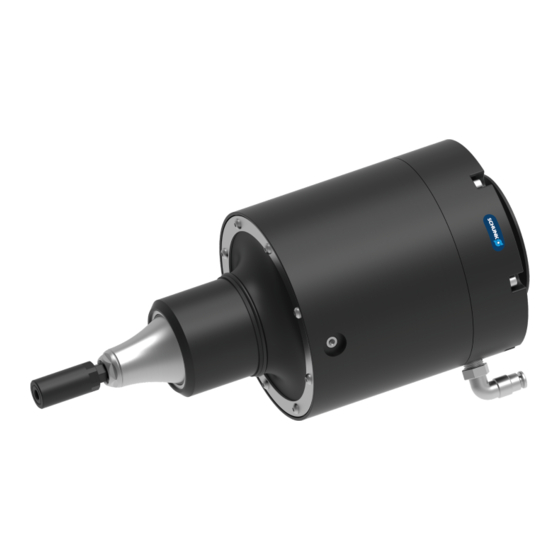
Page 15: Design And Description
Motor air connection Robot side connection (axial) Robot side connection (radial) Axis fixation set screw File holder 4.2 Description Pneumatically driven file with radial compensation for deburring workpieces 02.00 | CRT | Assembly and Operating Manual | en | 1453513... -
Page 16: Assembly And Settings
✓ 4. Install the automatic tool changer, Installing the automatic tool changer 20], if necessary. 5. If necessary, adjust the axis fixation set screw, Setting axis fixation 23]. 02.00 | CRT | Assembly and Operating Manual | en | 1453513... -
Page 17: Connections
Fitting bore for centering pin [mm] Max. depth of engagement from locating surface [mm] * Mounting material is not included in the scope of delivery. (available from SCHUNK on request) 02.00 | CRT | Assembly and Operating Manual | en | 1453513... -
Page 18: Pneumatic Connection
2-way valve and a pressure regulator set at max. 6.2 bar. Compensation air connection Motor air connection Item Mounting Compensation air connection [mm] Motor air connection [mm] 02.00 | CRT | Assembly and Operating Manual | en | 1453513... - Page 19 2/2 directional control valve Product Oil mist Filter lubricator Air motor Exhaust air / Air connection Silencer 6.2 bar 3/2 directional Compensation control valve Regulator Pneumatic wiring diagram 02.00 | CRT | Assembly and Operating Manual | en | 1453513...
-
Page 20: Installing The Automatic Tool Changer
For file tools: Remove file holder and any tools from the product. 3. Carefully screw on the automatic quick release (master side) for tool holders to the stop with a wrench from the accessory kit. 02.00 | CRT | Assembly and Operating Manual | en | 1453513... -
Page 21: Mount The Tool Stand Module
T-nut (2) into the extruded aluminum rail (4). 3. Tighten tool stand module with fastening screw (3). Max. tightening torque: 10 Nm. ✓ 4. Place the end cap (1) onto the extruded aluminum rail (4). 02.00 | CRT | Assembly and Operating Manual | en | 1453513... - Page 22 6. Pressurize air connection retract (3) with compressed air. Vent air connection extend (4). 7. Move the robot away from the tool stand module to the side. 8. Repeat steps 5 and 6 for the other tool holder. 02.00 | CRT | Assembly and Operating Manual | en | 1453513...
-
Page 23: Setting Axis Fixation
1. Adjust the screw to the desired position: Unlocked = 360° compensation ✓ Locked = Compensation only in X-axis ✓ 2. Manually check ease of movement and possible directions of movement for correct function. 02.00 | CRT | Assembly and Operating Manual | en | 1453513... -
Page 24: Operation
If this is not possible, several machining passes may be necessary. 5. When using the axis fixation, always set the free compensation axis of the product perpendicular to the edge of the workpiece. 02.00 | CRT | Assembly and Operating Manual | en | 1453513... -
Page 25: Troubleshooting
The pressure valve is defective. Change pressure valve. Ring cylinder assembly is Check ring cylinder assembly for damaged. wear and replace if necessary, Changing the ring cylinder assembly 30] 02.00 | CRT | Assembly and Operating Manual | en | 1453513... -
Page 26: Residue On The Workpiece After Deburring
Secure tool in file holder. Workpiece is approached too Check process parameters, fast or at an incorrect angle. reduce infeed, reduce air pressure for compensation, perform machining in several passes., Operation 24]. 02.00 | CRT | Assembly and Operating Manual | en | 1453513... -
Page 27: Maintenance
To maximize service life, only operate the motor for the product with lubrication in the air supply. To do this, lubricate the air supply to the motor with 1-2 drops of a standard pneumatic tool oil per minute. 02.00 | CRT | Assembly and Operating Manual | en | 1453513... -
Page 28: Changing The File
3. Remove file (3) from the file holder (2). 4. Insert the new file (3) into the file holder (2) and fasten it with screws (1). 5. Connect all compressed air lines. 02.00 | CRT | Assembly and Operating Manual | en | 1453513... -
Page 29: Changing The Spindle Boot
6. Install the new spindle boot (4) and boot ring (3) on the main housing (5) using mounting screws (2). Carefully tighten the screws hand-tight. ✓ 7. Tighten O-ring (1) over the spindle boot (4). 8. Connect all compressed air lines. 02.00 | CRT | Assembly and Operating Manual | en | 1453513... -
Page 30: Changing The Ring Cylinder Assembly
8. Place the main housing (2) on the rear housing assembly (5) and fasten with mounting screws (1). Max. tightening torque: 2.83 Nm ✓ 9. Connect all compressed air lines. 10. Mount product onto the system/machine. 02.00 | CRT | Assembly and Operating Manual | en | 1453513... -
Page 31: Assembly Drawings
Maintenance 8.7 Assembly drawings 02.00 | CRT | Assembly and Operating Manual | en | 1453513... -
Page 32: Translation Of Original Declaration Of Incorporation
Person authorized to compile the technical documentation: Robert Leuthner, Address: see manufacturer's address Lauffen/Neckar, January 2021 p.p. Ralf Winkler; Head of Technology & Engineering, Mechanics Gripping Systems 02.00 | CRT | Assembly and Operating Manual | en | 1453513... -
Page 33: Annex To Declaration Of Incorporation
Risks due to falling or ejected objects 1.3.4 Risks due to surfaces, edges or angles 1.3.5 Risks related to combined machinery 1.3.6 Risks related to variations in operating conditions 02.00 | CRT | Assembly and Operating Manual | en | 1453513... - Page 34 1.5.15 Risk of slipping, tripping or falling 1.5.16 Lightning Maintenance 1.6.1 Machinery maintenance 1.6.2 Access to operating positions and servicing points 1.6.3 Isolation of energy sources 1.6.4 Operator intervention 1.6.5 Cleaning of internal parts 02.00 | CRT | Assembly and Operating Manual | en | 1453513...
- Page 35 Supplementary essential health and safety requirements for machinery intended for underground work Supplementary essential health and safety requirements for machinery presenting particular hazards due to the lifting of persons 02.00 | CRT | Assembly and Operating Manual | en | 1453513...
- Page 36 Translation of Original Operating Manual SCHUNK GmbH & Co. KG Clamping and gripping technology Bahnhofstr. 106 - 134 D-74348 Lauffen/Neckar Tel. +49-7133-103-0 Fax +49-7133-103-2399 info@de.schunk.com schunk.com Folgen Sie uns I Follow us...
Need help?
Do you have a question about the CRT and is the answer not in the manual?
Questions and answers