Table of Contents
Advertisement
Quick Links
Advertisement
Table of Contents

Related Manuals for MicroTouch DT-150P-A1


Summary of Contents for MicroTouch DT-150P-A1
- Page 1 User Manual Version 4.0 2021/02 DT-150P-A1 Desktop Touch Monitor...
- Page 2 MicroTouch a TES Company. The information in this document is subject to change without notice. MicroTouch TES Company makes no representations or warranties with respect to the contents herein, and specifically disclaims any implied warranties of merchantability or fitness for a particular purpose.
- Page 3 Compliance Information For FCC (USA) This equipment has been tested and fund to comply with the limits for a Class A digital device, pursuant to part 15 of the FCC Rules. There limits are designed to provide reasonable protection against harmful interference when the equipment is operated in a commercial environment.
- Page 4 Renseignements relatifs à la conformité Pour la FCC (États-Unis). Ce matériel a fait l’objet d’essais qui ont déterminé qu’il respectait les limites d’un appareil de classe A selon la partie 15 des règlements de la FCC. Ces limites sont établies pour assurer une protection raisonnable contre les parasites nuisant à...
- Page 5 Usage Notice Warning - To prevent the risk of fire or shock hazards, and do not expose the product to moisture. Warning - Please do not open or disassemble the product as this may cause electric shock. Warning - Power cord shall be connected to a socket-outlet with earthing connection.
- Page 6 Avis d’utilisation Mise en garde — Pour prévenir les risques d’incendie ou d’électrocution, ne pas exposer le produit à l’humidité. Mise en garde — Prière de ne pas ouvrir ou démonter le produit, car cela pourrait entraîner l’électrocution. Mise en garde – Le cordon d’alimentation doit être branché à une prise pourvue d’une mise à...
-
Page 7: Table Of Contents
Table of Contents Chapter 1 ........................7 1.1 Overview ........................8 1.2 Feature ........................8 1.3 Specifications ......................8 1.4 Block Diagram......................10 1.5 Interface Connectors ....................11 1.5.1 Power Connector ..................... 11 1.5.2 Video Signal Connector ................... 11 1.6 Package Overview ....................19 Chapter 2 ........................ -
Page 8: Chapter 1
Chapter 1 Product Introduction... -
Page 9: Overview
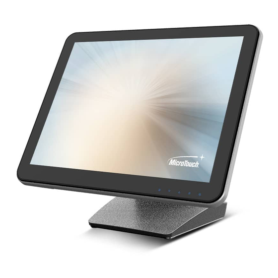
The DT-150P-A1 series is an ultra-modern 15" monitor that offers a unique screwless design with expandability and flexibility, making expansion and accessory installation much easier. The versatility of DT-150P-A1 is an exceptional choice for applications in all business sectors, especially in the retail market. - Page 10 Operating Temperature 0C ~ 40C Storage Temperature -20C ~ 60C Operating Humidity 0% ~ 90% RH, non-condensing Mounting VESA 100 mm x 100 mm Dimension (W x H x D) 356.1 mm x 309.3 mm x 201.4 mm Net Weight 4.2 Kg Gross Weight 6.8 Kg...
-
Page 11: Block Diagram
1.4 Block Diagram... -
Page 12: Interface Connectors
1.5 Interface Connectors Monitor Only 1.5.1 Power Connector The AC adapter shall supply 12 5% voltage and at least 4 Ampere to system board. The power cord, exact type to be supplied in the appropriate Option Kit, shall be length of 1.8 ... - Page 13 ML_Lane 3(p) Data3 + Signal ground ML_Lane 2(n) Data2 - Signal ground AUX_CH(p) AUX + Signal for Signal ground Auxiliary Channel ML_Lane 2(p) Data2 + Signal ground AUX_CH(n) AUX - Signal for ML_Lane 1(n) Data1 - Auxiliary Channel Signal ground Hot Plug ML_Lane 1(p) Data1 + DP_PWR Return...
- Page 14 Signal Signal GREEN BLUE HSYNC RED_GND VSYNC GREEN_GND BLUE_GND USB 2.0 Signal USB5V Note Every on USB2.0 Power current provide 1A(Regular)
- Page 15 Line In Signal Left CH Right CH Left CH Right CH Note Every on USB2.0 Power current provide 1A(Regular) Side IO (Option) USB 2.0 Signal USB5V...
- Page 16 Side IO (Option) Signal Signal USB5V RI/5V/12V Note USB for Camera module Simple COM for LCM module Internal Connector AMP_CON(Speaker out) Signal ROUTP ROUTN LOUTN LOUTP...
- Page 17 Internal Connector USB (For Camera) Signal Internal Connector USB (For MSR) Signal Internal Connector USB (For Touch) Signal...
- Page 18 Internal Connector USB (For LCM) Signal EDP connector Signal Signal T-con VCC T-con VCC T-con VCC BLK_VCC BLK_VCC BLK_VCC BLK_VCC Lane1_P Lane1_N Lane0_P Lane0_N BL_ADJ...
- Page 19 BL_ON/OFF AUX_P AUX_N Internal Connector Panel power and BLU adjust connector Signal Signal BLU_VCC BLU_VCC BLU_VCC BL_ADJ BL_EN Internal Connector OSD Touch Key connector (FFC Type) Signal Signal +3.3V +3.3V +3.3V GPIO WAKE...
-
Page 20: Package Overview
1.6 Package Overview LCD Display Power Cord DC Power Supply Stand (Optional) (Optional) USB cable (A to B) VGA cable Audio cable... - Page 21 This product is intended to be supplied by a Listed Power Adapter or DC power source, rated 12Vdc, 4.16A minimum, Tma = 40 degree C minimum, and the altitude of operation = 3048m minimum. If it needs further assistance with purchasing the power source, please contact to MicroTouch for further information. Mise en garde! Cet appareil est conçu avec une alimentation de courant CA, d’une tension...
-
Page 22: Chapter 2
Chapter 2 Product Installation... -
Page 23: About Vesa Mount
2.1 About VESA Mount The DT-150P-A1 series conform to the “VESA Flat Display Mounting Interface Standard” which defines a physical mounting interface for touch monitor, and corresponding with the standards of touch monitor mounting devices, such as wall-mounted or pole-mounted. The VESA mount is located on the back of this unit. -
Page 24: On-Screen Display
2.2 On-Screen Display Menu off status Menu on status Menu appear Menu disappear/ return to main item Mute Main item select down/ Adjust down Brightness Main item select up/ Adjust up Enter/Select sub-item function Power On/Off Press the “MENU” button to pop up the “on-screen menu” and press “Up” or “Down”... - Page 25 (Please note: the monitor has to be turned ON with a valid signal pre-set) Press the " Enter " key 5 time, The “Lock/Unlock” menu will appear for 3 seconds. Use the "Enter" key to select OSD or Power setting then set at “Lock” by pushing the "UP"...
-
Page 26: Osd Function Description
2.2.1 OSD Function Description ITEM CONTENT Default Contrast The monitor luminance level control. Brightness The monitor backlight level control. Auto Adjust Fine-tune the image to full screen automatically. Left/Right Moving screen image horizontal position to left or right. Up/Down Moving screen image vertical position to up or down. Horizontal size The screen image horizontal dot clock adjustment. -
Page 27: Timing Table Chart
2.2.2 Timing Table Chart Polarity Band Width Mode Resolution H-Freq. (KHz) (MHz) VGA 720x400 70Hz 31.47 28.322 VGA 640x480 60Hz 31.47 25.175 MAC 640x480 66Hz 32.24 VESA 640x480 72Hz 37.86 31.5 VESA 640X480 75Hz 37.5 31.5 VESA 800x600 56Hz 35.16 VESA 800x600 60Hz 37.88 VESA 800x600 75Hz... -
Page 28: Dimension
2.3 Dimension 2.3.1 Front View 2.3.2 Side View... -
Page 29: Rear View
2.3.3 Rear View 2.3.4 Bottom view... -
Page 30: Optional Accessory Installation
2.4 Optional Accessory Installation 2.4.1 Install the Stand Step 1: Install the top of optional stand first. Step 2: Push it to the touch monitor and fasten the screws. Step 1 Step 2 2.4.2 Dismantle the Stand Loosen the screws (right side and left side) and pull down the stand. -
Page 31: Install The Cables
Install 2.4.3 the Cables Pull down the I/O cover for cables installation. -
Page 32: Install The Lcm Or 9.7'' 2
Install the LCM or 9.7’’ 2 Display 2.4.4 tool Step 1: Use a hard to poke the cover out easily. Step 1 Step 2: Push the LCM. Step 2 Step 3: Fasten the screws Step 3... -
Page 33: Dismantle The Lcm Or 9.7"2Nd Display
the LCM 2.4.5 Dismantle Step 1: Loosen the screws. tool Step 2: Use a hard to poke the LCM... -
Page 34: Install The Msr
Install the 2.4.6 tool Step 1: Use a hard to poke the cover out easily. Step 2: Push the MSR to the touch computer. Step 2... -
Page 35: Dismantle The Msr
2.4.7 Dismantle the MSR Step 1: Remove the MSR cover first. Step 1 Step 2: Press the hooks and pull out the MSR. Step 2... -
Page 36: Appendix
Appendix... - Page 37 Declaration of the Presence Condition of the Restricted Substances Marking 設備名稱:觸控螢幕 型號(型式):DT-150P-A1 Type designation (Type) :DT-150P-A1 Equipment name:Touch Screen LCD Monitor 限用物質及其化學符號 Restricted substances and its chemical symbols 單元 Unit 六價鉻 多溴聯苯 多溴二苯醚 鉛 汞 鎘 Cadmium Hexavalent Polybrominated Polybrominated...
Need help?
Do you have a question about the DT-150P-A1 and is the answer not in the manual?
Questions and answers