Table of Contents
Advertisement
Quick Links
Advertisement
Table of Contents

Related Manuals for Seeley MAGICTOUCH MS1


Summary of Contents for Seeley MAGICTOUCH MS1
- Page 1 INSTALLATION & OPERATION MANUAL MagIQtouch BMS Industrial Controller MS1 (Coolers Only) B M S IN D B M S IN D U S T R IA L U S T R IA L C O N T R O C O N T R O L L E R M S L L E R M 1 P W R /...
- Page 2 ™ ™...
-
Page 3: Table Of Contents
TABLE of contents KIT CONTENTS SAFETY EMPLOYER AND EMPLOYEE RESPONSIBILITIES Installer and Maintenance Contractors – Risk Assessment Other Important Points to Consider: INSTALLATION PREPARATION COMMUNICATION CABLE Master Mode - Maximum Cable Length Slave Mode - Maximum Cable Length INSTALLATION Mounting - Din Rail Mounting - Wall Mount ELECTRICAL INSTALLATION Typical Installation Options... -
Page 4: Kit Contents
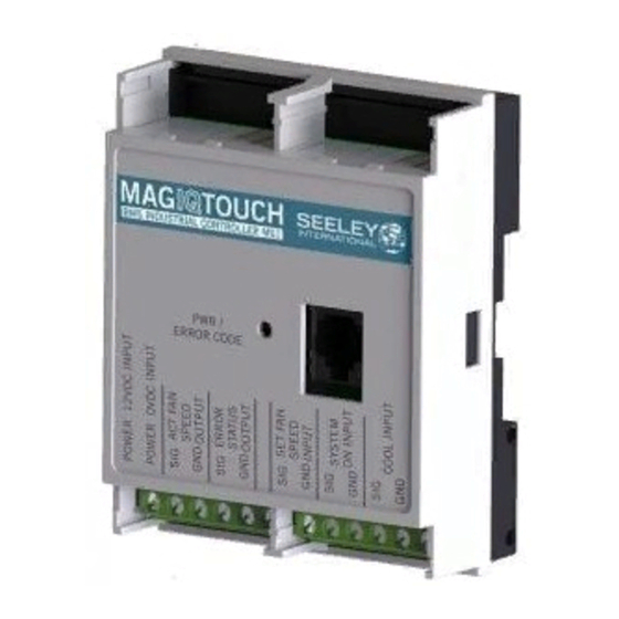
KIT CONTENTS Contents Item Images Qty Description BM S IND BM S IND US TR IAL US TR IAL CO NT RO CO NT RO LLE R MS LL ER M1 MaglQtouch Industrial Controller MS1 PW R / ER RO R CO ILL2470-A INSTALLATION &... -
Page 5: Safety
INSTALLER AND MAINTENANCE CONTRACTORS – RISK ASSESSMENT Seeley International provides the following information as a guide to contractors and employees to assist in minimising risk whilst working at height. A risk assessment of all hazardous tasks is required under legislation. A risk assessment... -
Page 6: Installation Preparation
INSTALLATION PREPARATION WARNING! THIS INSTALLATION SHOULD ONLY BE PERFORMED BY SUITABLY TRAINED AND QUALIFIED PERSONNEL, IN ACCORDANCE WITH LOCAL AND NATIONAL WIRING RULES. Before commencing work on the cooler, ensure it is disconnected from the power source, when installing the MagIQtouch BMS Industrial Controller select and prepare an appropriate mounting site with the following features: •... -
Page 7: Communication Cable
Controller are 26AWG, 7/0.16, 6 core flat cable. • 20m/66’ cable is supplied with each Seeley cooler or heater. Important! Supplied cables should not be altered. Failure of the product or components to operate correctly due to modification to supplied cables, or the use of non-approved cable will NOT be accepted under the Manufacturer’s warranty. - Page 8 COMMUNICATION CABLE cont. Should your installation require addition cables, 'genuine' Seeley International components can be ordered as follows; Part No. Length Details 862873 1.5m/5' MagIQtouch Industrial Wall Controller cable (No ferrite) 861265 3m/10' MagIQtouch Industrial Wall Controller cable (No ferrite) 833880 20m/66’...
-
Page 9: Installation
INSTALLATION MOUNTING - DIN RAIL BMS MS1 is suitable for internal installations only. The MagIQtouch BMS Controller is fitted with a DIN rail retainer on the rear of the enclosure. Locate the top catches onto the rail first, pivot down then secure the bottom catches onto the rail where the DIN rail retainer will click into place. -
Page 10: Electrical Installation
ELECTRICAL INSTALLATION TYPICAL INSTALLATION OPTIONS Installation of the cooler, wall controller and MagIQtouch BMS Industrial Con- troller must conform to local, national and international electrical safety and wiring regulations. Refer to the cooler installation manual for installation and electrical connection of cooler. MASTER MODE - SINGLE COOLER NOTE: 1 x BMS MS1 Master per 1 x cooler EVAP COOLER 1... - Page 11 ELECTRICAL INSTALLATION cont. SLAVE MODE - SINGLE COOLER option 1 EVAP COOLER 1 BMS MS1 LINK MODULE BMS INDUSTRIAL CONTROLLER M1 BMS INDUSTRIAL CONTROLLER MS1 CUSTOMER PWR / ERROR CODE ILL2476-B ILL2476-B SLAVE MODE - SINGLE COOLER option 2 EVAP COOLER 1 BMS INDUSTRIAL CONTROLLER M1 BMS INDUSTRIAL CONTROLLER MS1 CUSTOMER...
- Page 12 ELECTRICAL INSTALLATION cont. SLAVE MODE - Multiple Coolers Option 1 (With link modules) ILL2478-B SLAVE MODE - Multiple Coolers Option 2 (With Dual RJ socket on Cooler electronics) ILL2479-C ™...
-
Page 13: Master Or Slave Mode
ELECTRICAL INSTALLATION cont. Master or Slave Mode The BMS MS1 controller can be used as either a 'Master' or 'Slave' Controller. Master Mode The BMS MS1 is controlled with BMS signals only and no MagIQtouch wall controller can be used. Only 1 x BMS MS1 per 1 x cooler can be used in this configuration. -
Page 14: Connecting Cooler Or Wall Control To Bms Ms1
ELECTRICAL INSTALLATION cont. CONNECTING COOLER OR WALL CONTROL TO BMS MS1 ILL2481-A ILL2481-A ™... -
Page 15: Inputs Signals
BMS INDUSTRIAL CONTROLLER M1 BMS INDUSTRIAL CONTROLLER MS1 ELECTRICAL INSTALLATION cont. PWR / INPUTS SIGNALS - DIGITAL ERROR CODE ILL2482-A Name Label Function High Input Type Master mode only: Turn Cooler Cooler Off Cooler On Digital 10Vdc On or Off SYSTEM On/Off Slave mode only: Switch... -
Page 16: Voltage Levels For Set Fan Speed Analogue Input
ELECTRICAL INSTALLATION cont. INPUTS SIGNALS - ANALOGUE Recommended voltage levels for Set Fan Speed analogue input. Increasing Decreasing Set Fan Speed (0 - 10) (10 - 0) ▼ 10.0 ▲ [Optional] 12Vdc power input (POWER IN 12VDC) Power input only required if ACT FAN SPEED and ERROR STATUS signals are required from the module. -
Page 17: Output Signals
ELECTRICAL INSTALLATION cont. OUTPUT SIGNALS - ERROR STATUS The diagram shows the internal circuit of the Error Status output. POWER IN 12V 470R ERROR + RXE005 ISMA4753 ERROR - BC640 BMS DC POWER RAIL V+ PULL UP RESISTOR POWER IN 0V ERROR+ Monitor Voltage: ILL2483-B... -
Page 18: Actual Fan Speed
ELECTRICAL INSTALLATION cont. OUTPUT SIGNALS - ACTUAL FAN SPEED Actual Fan VOUT VOUT VOUT Speed 10.3 12.0 Exact voltage levels may differ depending on the precision of the POWER IN 12V supply. ™... -
Page 19: Diagnostic Led's
DIAGNOSTIC LED's PWR / ERROR CODE LED Diagnostic and cooler operating information can be viewed from the MagIQtouch BMS Industrial Controller via the Error Code LED's. When power is applied to the RJ port of the BMS module MS1 and no error is detected the LED will illuminate continuously. -
Page 20: Connection Diagram
CONNECTION DIAGRAM ILL2512-B ™... -
Page 21: Trouble Shooting
TROUBLE SHOOTING Symptom Cause Action Cable not connected correctly Refit cable. Cycle power to cooler. The PWR LED is not illuminated. Cable damaged or broken. Replace cable. Cycle power to cooler. The BMS MS1 configured in incorrect Open enclosure and correct dipswitch mode (Master/Slave). - Page 24 For regions outside Australia: Contact your local Dealer seeleyinternational.com MANUFACTURED BY: Seeley International Pty Ltd, 112 O’Sullivan Beach Road, Lonsdale, SA 5160, Australia (for Australia, USA, Europe and South Africa) IMPORTED BY: Seeley International (Americas) Ltd, 1002 S 56th Avenue, Suite# 101...
Need help?
Do you have a question about the MAGICTOUCH MS1 and is the answer not in the manual?
Questions and answers