
Subscribe to Our Youtube Channel
Related Manuals for MICROENER IM30-B00


Summary of Contents for MICROENER IM30-B00
- Page 1 IM30-B00 MO-0132-ING Doc. N° MICROPROCESSOR EARTH FAULT PROTECTION RELAY TYPE IM30-B00 OPERATION MANUAL Copyright 2010 - Microener Firmware Data Rev. 2.0X 22.04.2008...
-
Page 2: Table Of Contents
21. Direction for Pcb's Draw-Out and Plug-In ____________________________________________________________ 20 21.1 - Draw-out ____________________________________________________________________________________ 20 21.2 - Plug-in _____________________________________________________________________________________ 20 22. Mounting _______________________________________________________________________________________ 21 23. Keyboard Operational Diagram _____________________________________________________________________ 22 24. Setting’s Form___________________________________________________________________________________ 23 Copyright 2010 - Microener Firmware Data Rev. 2.0X 22.04.2008... -
Page 3: General Utilization And Commissioning Directions
The electronic circuits reduced by M.S. are completely safe from electrostatic discharge (8 KV IEC 255.22.2) when housed in their case; withdrawing the modules without proper cautions expose them to the risk of damage. Copyright 2010 - Microener Firmware Data Rev. -
Page 4: Maintenance
80V(-20%) / 220V(+15%) a.c. a) - b) - 24V(-20%) / 125V(+20%) d.c. 90V(-20%) / 250V(+20%) d.c. Before energising the unit check that supply voltage is within the allowed limits. Copyright 2010 - Microener Firmware Data Rev. 2.0X 22.04.2008... -
Page 5: Algorithm Of The Time Current Curves
Where Kt = (10 -1)Ts is the time multiplier Copyright 2010 - Microener Firmware Data Rev. 2.0X 22.04.2008... -
Page 6: Clock And Calendar
During power on, time tolerance depends on the on board crystal (+/-50ppm typ, +/-100ppm max. over full temperature range). During power off, time tolerance depends on the RTC’s oscillator (+65 /–270 ppm max over full temperature range). Copyright 2010 - Microener Firmware Data Rev. -
Page 7: Controls And Measurements
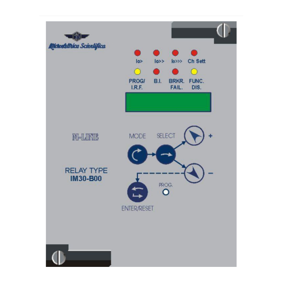
3. Controls and Measurements Five key buttons allow for local management of all relay's functions. A 8-digit high brightness alphanumerical display shows the relevant readings (xxxxxxxx) (see synoptic table fig.1) FIG.1 Copyright 2010 - Microener Firmware Data Rev. 2.0X 22.04.2008... -
Page 8: Signalizations
From ON to OFF, automatically when the lit-on cause disappears. In case of auxiliary power supply failure the status of the leds is recorded and reproduced when power supply is restored. Copyright 2010 - Microener Firmware Data Rev. 2.0X... -
Page 9: Output Relays
Each relay is identified by its programmable address code (NodeAd) and can be called from the P.C. A dedicated communication software (MSCom) for Windows 95/98/NT4 SP3 (or later) is available. Please refer to the MSCom instruction manual for more information Microelettrica Scientifica. Copyright 2010 - Microener Firmware Data Rev. -
Page 10: Digital Inputs
4ms). If any internal fault is detected, the display shows a fault message, the Led "PROG/IRF" illuminates and the relay R5 is deenergized. Complete test activated by the keyboard or via the communication bus either with or without tripping of the output relays. Copyright 2010 - Microener Firmware Data Rev. 2.0X... -
Page 11: Keyboard And Display Operation
ENTER/RESET : It allows the validation of the programmed settings - the actuation of test programs - the forcing of the default display indication - the reset of signal Leds. e) - PROG. : Enables access to the programming. Copyright 2010 - Microener Firmware Data Rev. 2.0X 22.04.2008... -
Page 12: Reading Of Measurements And Recorded Parameters
RELAY", scroll information available in the menu by keys "+" or "-". SETTINGS= values of relay's operation parameters as programmed RELAY= output relays associated to the different functions as programmed. Copyright 2010 - Microener Firmware Data Rev. 2.0X 22.04.2008... -
Page 13: Programming
0.05 Time delay for Breaker Failure alarm 0.05 - 0.75 0.01 5-10 Tsyn Synchronisation Time 5 - 60 - Dis 15-30 60-Dis The setting Dis indicates that the function is disactivated. Copyright 2010 - Microener Firmware Data Rev. 2.0X 22.04.2008... -
Page 14: Programming The Configuration Of Output Relays
2xtBF (tB2 = 2xtBF). 2tBF As above, for the earth fault elements (tB3 = Dis) or (tB3 = 2tBF). Copyright 2010 - Microener Firmware Data Rev. -
Page 15: Manual Test Operation
This is extremely important as discharges eventually tacking place in other parts or components of the board can severely damage the relays or cause damages, not immediately evident to the electronic components. Copyright 2010 - Microener Firmware Data Rev. -
Page 16: Electrical Characteristics
Tel. (+39) 02 575731 - Fax (+39) 02 57510940 http://www.microelettrica.com e-mail : sales.relays@microelettrica.com The performances and the characteristics reported in this manual are not binding and can modified at any moment without notice Copyright 2010 - Microener Firmware Data Rev. 2.0X... -
Page 17: Connection Diagram
IM30-B00 MO-0132-ING Doc. N° 17. Connection Diagram 18. Wiring the Serial Communication Bus Copyright 2010 - Microener Firmware Data Rev. 2.0X 22.04.2008... -
Page 18: Time Current Curves Iec (Tu0388 Rev.0 1/2)
IM30-B00 MO-0132-ING Doc. N° 19. Time Current Curves IEC (TU0388 Rev.0 1/2) Copyright 2010 - Microener Firmware Data Rev. 2.0X 22.04.2008... -
Page 19: Time Current Curves Ieee (Tu0388 Rev.0 2/2)
IM30-B00 MO-0132-ING Doc. N° 20. Time Current Curves IEEE (TU0388 Rev.0 2/2) Copyright 2010 - Microener Firmware Data Rev. 2.0X 22.04.2008... -
Page 20: Direction For Pcb's Draw-Out And Plug-In
Slide-in the card on the rails provided inside the enclosure. Plug-in the card completely and by pressing the handle to the closed position. Rotate anticlockwise the screws and with the mark in the vertical position (locked). Copyright 2010 - Microener Firmware Data Rev. -
Page 21: Mounting
IM30-B00 MO-0132-ING Doc. N° 22. Mounting Copyright 2010 - Microener Firmware Data Rev. 2.0X 22.04.2008... -
Page 22: Keyboard Operational Diagram
IM30-B00 MO-0132-ING Doc. N° 23. Keyboard Operational Diagram Copyright 2010 - Microener Firmware Data Rev. 2.0X 22.04.2008... -
Page 23: Setting's Form
HI The blocking of the elements 1I, 2I 2tBF 2tBF As above, for the earth fault elements Commissioning Engineer : Date : Customer Witness : Date : Copyright 2010 - Microener Firmware Data Rev. 2.0X 22.04.2008...
Need help?
Do you have a question about the IM30-B00 and is the answer not in the manual?
Questions and answers