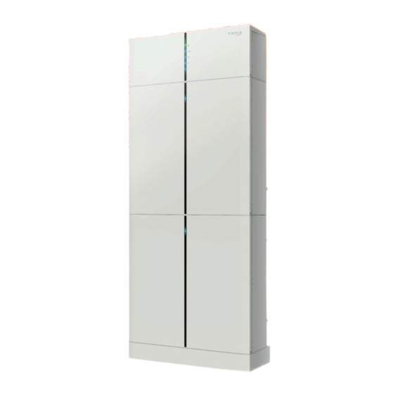
SolaX Power MC0600 User Manual

SolaX Power MC0600 User Manual

Triple power lithium-ion battery

Advertisement

Solax Power Network Technology(Zhe jiang) Co., Ltd.
Triple Power Lithium-ion Battery
30Ah
Copyright Declaration
The copyright of this manual belongs to SolaX Power Network Technology(Zhe jiang) Co.,
Ltd. Any corporation or individual should not plagiarize, partially or fully copy (including
software,etc.), and no reproduction or distribution of it in any form or by any means. All
rights reserved. SolaX Power Network Technology (Zhe jiang) Co.,Ltd. reserves the right
614.00519.00
of final interpretation.
User Manual

Advertisement

Table of Contents
loading
Need help?

Need help?

Do you have a question about the MC0600 and is the answer not in the manual?

Questions and answers

Subscribe to Our Youtube Channel

Summary of Contents for SolaX Power MC0600

  • Page 1 Solax Power Network Technology(Zhe jiang) Co., Ltd. Copyright Declaration The copyright of this manual belongs to SolaX Power Network Technology(Zhe jiang) Co., Ltd. Any corporation or individual should not plagiarize, partially or fully copy (including software,etc.), and no reproduction or distribution of it in any form or by any means. All rights reserved.
  • Page 2: Table Of Contents

    Contents NOTE ON THIS MANUAL ..................... SCOPE OF VALIDITY..................TARGET GROUP....................SYMBOLS USED....................SAFETY..........................SAFETY INSTRUCTIONS.................. 2.1.1 GENERAL SAFETY PRECAUTIONS............... 2.1.2 EXPLANATION OF SYMBOLS................. RESPONSE TO EMERGENCY SITUATIONS..........2.2.1 LEAKING BATTERIES..................2.2.2 FIRE........................... 2.2.3 WET BATTERIES AND DAMAGED BATTERIES.......... QUALIFIED INSTALLER..................PRODUCT INTRODUCTION..................
  • Page 3: Note On This Manual Scope Of Validity

    T-BAT Module COMMISSIONING..................HV10230 STATUS INDICATORS................5.2.1 BMS(MC0600).................... Note: There are 4 models of the T-BAT system, which include the BMS and battery 5.2.2 BATTERY MODULE (HV10230).............. module(s). Refer to section 3.3.1 T-BAT SYS-HV Configuration List onpage 11 SHUTTING DOWN T-BAT SYSTEM............
  • Page 4: Safety

    2. Safety 2. Safety Safety 2.1.2 Explanation of Symbols Safety Instructions Symbol Explanation For safety reasons, installers are responsible for familiarizing themselves with the contents of this manual and all warnings before performing installation. CE mark. 2.1.1 General Safety Precautions The inverter complies with the requirements of the applicable CE guildlines.
  • Page 5: Response To Emergency Situations

    2. Safety 2. Safety Response to Emergency Situations Qualified Installer 2.2.1 Leaking Batteries If the battery leaks electrolyte which is corrosive, avoid contact with the leaking WARNING! liquid or gas. Direct contact may lead to skin irritation or chemical burns. If one is All operations of T-BAT SYS-HV relating to electrical connection and exposed to the leaked substance, perform these actions: installation must be carried out by qualified personnel.
  • Page 6: Product Introduction

    A battery management system (BMS) is an electronic system that manages a rechargeable battery. ≥300mm A battery module is a type of electrical battery which can be charged or discharged into a load. A battery system includes theBMS and battery module(s). BaseMounting MC0600 HV10230 Length 482mm 482.5mm 482.5mm Width 167mm 173.5mm...
  • Page 7: Appearance

    3. Product Introduction 3. Product Introduction Section view of HV10230 3.1.3 Appearance Ÿ Section view of MC0600 Ÿ I’ IV’ VIII VI’ II’ III’ V’ Object Mark Description Object Mark Description Connector B+ of BMS, or B- of upper/next battery module I’...
  • Page 8: Basic Features

    The T-BAT SYS-HV is one of the most advanced energy storage systems on Battery Module Energy(kWh) Voltage (V) Model the market today, incorporating state-of-the-art technology, high reliability, and convenient control features shown as below: T-BAT H 3.0 MC0600×1 90-116 HV10230×1 90% DOD T-BAT H 6.0 MC0600×1 HV10230×2 180-232 Ÿ...
  • Page 9: Installation

    4. Installation 4. Installation Tools Installation These tools are required to install the T-BAT system. Installation Prerequisites When assembling the system, avoid touching the battery terminal with any metal objects or bare hands. T-BAT SYS-HV provides a safe source of electrical energy when operated as designed.
  • Page 10: Accessories

    Note:A3×1 and A3×1 need to be purchased separately Copyright Declaration The copyright of this manual belongs to SolaX Power Co.,Ltd.. Any corporation or individual should not plagiarize, partitially copy or fully copy(including software,etc.), and no reproduction or distribution of it in any form or by any means. All rights reserved.
  • Page 11: Overall Installation

    4. Installation 4. Installation 4.4.4 Overall Installation According to the battery used, choose the following corresponding form for installation. It is recommended to use corrugated pipe protect the outside cables between three and four battery modules. 1):MC0600×1+HV10230×1 2):MC0600×1+HV10230×2 3):MC0600×1+HV10230×3...
  • Page 12: Install Bms To Battery Module

    4. Installation 4.4.5 Install BMS to Battery Module 4):MC0600×1+HV10230×4 Make sure the wall is strong enough to withstand the weight of battery. Step 1: Fix the base mounting ·Firstly, adjust the height of the anchor bolt to make it parallel to the ground.
  • Page 13 4. Installation 4. Installation Take two battery module s as an example Fix the battery module and wall bracket with expansion bolts. (I,N and K) · One battery module or connected to the BMS, need to be installed a Step 3: Match the battery with base mounting bracket to fix.
  • Page 14: Cable Connection

    4. Installation 4. Installation Cable Connection Cable Connection Steps: Ø Before connecting the cables, the right cover of the battery needs to be unscrewed Step1. Strip the cable(A/B:2m) to 15mm. by hand Step2. Insert the stripped cable up to the stop (negative cable for DC plug(-) and positive cable for DC socket(+) are live).
  • Page 15: Connecting The Comm Ciommunication Cable

    4. Installation 4. Installation Notes for Unplugging Power Cables 4.5.2 Connecting theCOMM Communication Cable 1) Connect the COMM communication cable (E) from the right side of the BMS to CAUTION! the COM1 communication port that is on the right side of the battery module. Do not plug or unplug the power cables when the T-BATsystem is 2) Connect theCOM1 of theupper battery module on the right side to on.
  • Page 16: Connecting Cables To Battery Modules

    4. Installation 4. Installation 4.5.4 Connecting Cables to attery Modules For two battery modules: Ø Ensure that both ends of the cables are connected to the correct connector, Install a fixed wall bracket on the battery module, and thencheck to make sure the connections are securely locked.
  • Page 17 4. Installation 4. Installation For three battery modules: Check to make sure the connections are securely locked. Ø Ø Install a fixed wall bracket on the battery modules. BMS to Slave1: It (slave3 and slave4 if you need) is required to install the snap-fits to fix the cover plate. B+ to B+ (C:120mm);...
  • Page 18 4. Installation 4. Installation For four battery modules: The slave3 or slave4 needs to be Ø grounded, and the user can connect the Install a fixed wall bracket on the battery module, and thencheck to make sure the connections are securely locked. groud cable to the slave2 or slave1 through the pipe or ground separately according to the local regulations.
  • Page 19: Commissioning

    5. Commissioning 5. Commissioning Commissioning Status Indicators 5.2.1 Battery Module (MC0600) COMMISSIONING The LED indicators on the front panel of the battery pack are showing the Verify the model number of each battery module to ensure thatthey are allthe operating status.
  • Page 20: Bms(Mc0600)

    5. Commissioning 5. Commissioning Shutting Down T-BAT System 5.2.2 Battery Module (HV10230) To shut down the system, follow the steps described below: 1) Turn off the breaker between the inverter and T-BAT System 2) Long press 10s to shut down the BMS 3) Turn off the system by moving the circuit breaker switch to the OFF position 4) Ensure that every indicator on the T-BAT system is off 5) Disconnect the cables...
  • Page 21: Troubleshooting

    6. Troubleshooting 6. Troubleshooting Troubleshooting Warning Messages Description Troubleshooting Troubleshooting Battery over Wait until the temperature of the BMS_TemHigh Check the previous indicators to determine the status of the T-BATsystem. temperature cells returns to the normal state. A warning state is triggered when conditions such as voltage or temperature exceed the design limitations.
  • Page 22: Decommissioning

    8.Maintenance 7. Decommissioning Decommissioning Maintenance Dismantling the Battery Shutting down the battery unit If the ambient temperature for storage is -4-113°F, recharge the batteries Disconnect the cables betweenthe BMS and inverter at least one time every 3 months. Ÿ Disconnect the series wiring terminal on the battery Ÿ...
  • Page 23: Disclaimer

    9. Disclaimer Disclaimer Triple Power protects this product under warranty when it is installed and used as listed in this manual. Violation of the installation procedure or use of the product in any way not described in this manual will immediately void all warranties on the product.

Table of Contents