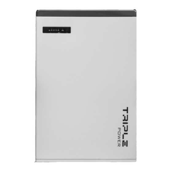
SolaX Power Triple Power T-BAT PACK-HV User Manual

SolaX Power Triple Power T-BAT PACK-HV User Manual

Lithium-ion battery 50ah

Advertisement

Triple Power Lithium-ion Battery
User Manual
50Ah
Solax Power Network Technology(Zhe jiang) Co,. Ltd.
Copyright Declaration
The copyright of this manual belongs to Solax Power Network Technology(Zhe jiang) Co,. Ltd.
(SolaX Power Co.,Ltd.). Any corporation or individual should not plagiarize, partitially or fully copy
(including software,etc.), and no reproduction or distribution of it in any form or by any means. All
rights reserved. SolaX Power Network Technology (Zhe jiang) Co.,Ltd. (SolaX Power Co.,Ltd.).
614.00425.01
reserves the right of final interpretation.

Advertisement

Table of Contents
loading
Need help?

Need help?

Do you have a question about the Triple Power T-BAT PACK-HV and is the answer not in the manual?

Questions and answers

Summary of Contents for SolaX Power Triple Power T-BAT PACK-HV

  • Page 1 Solax Power Network Technology(Zhe jiang) Co,. Ltd. Copyright Declaration The copyright of this manual belongs to Solax Power Network Technology(Zhe jiang) Co,. Ltd. (SolaX Power Co.,Ltd.). Any corporation or individual should not plagiarize, partitially or fully copy (including software,etc.), and no reproduction or distribution of it in any form or by any means. All rights reserved.
  • Page 2: Table Of Contents

    CONTENTS NOTE ON THIS MANUAL...............1 SCOPE OF VALIDITY..................1 TARGET GROUP....................1 SYMBOLS USED....................1 SAFETY....................2 SAFETY INSTRUCTIONS..................2 2.1.1 GENERAL SAFETY PRECAUTIONS...............2 2.1.2 EXPLANATION OF SYMBOLS.................3 RESPONSE TO EMERGENCY SITUATIONS..........5 2.2.1 LEAKING BAT TERIES..................5 2.2.2 FIRE...........................5 2.2.3 WET BAT TERIES AND DAMAGED BAT TERIES..........5 QUALIFIED INSTALLER..................6 PRODUCT INTRODUCTION..............7 PRODUCT OVERVIEW..................7...
  • Page 3: Note On This Manual

    Note on this Manual CABLE CONNECTION..................18 Scope of Validity 4.5.1 CONNECTING POWER CABLES..............18 This manual is an integral part of T-BAT Series. It describes the assembly, 4.5.2 CONNECTING POWER LINES................20 installation, commissioning, maintenance and failure of the product. Please read 4.5.3 CONNECTING CAN COMMUNICATION CABLE........24 it carefully before operating.
  • Page 4: Safety

    Storage Temperature: -20~+55℃ – Do not expose the battery pack to temperatures in excess of 55°C. SolaX Power Network Technology (Zhejiang) Co., Ltd ADD: No.288 Shizhu Road, Tonglu Economic Development Zone, – Do not place the battery pack near a heat source, such as a fireplace.
  • Page 5: Response To Emergency Situations

    Response to Emergency Situations Symbol Explanation 2.2.1 Leaking Batteries If the battery leaks electrolyte which is corrosive, avoid contact with the leaking liquid or gas. Direct contact may lead to skin irritation or chemical burns. If one is exposed to the leaked substance, do these actions: TUV mark for IEC62619 Accidental inhalation of harmful substances: Evacuate people from the contaminated area , and seek medical attention immediately.
  • Page 6: Qualified Installer

    3. Product Introduction Qualified Installer Product Introduction Product Overview WARNING! For safety reasons, installers are responsible for familiarizing themselves with the contents of this manual and all warnings before performing installation. All operations of T-BAT SYS-HV relating to electrical connection and installation must be carried out by qualified personnel.
  • Page 7: Appearance

    3. Product Introduction 3. Product Introduction Section view of HV11550 Ÿ 3.1.2 Appearance Section view of T-BAT H 5.8 Ÿ Ⅰ Ⅴ Ⅵ Ⅰ’ Ⅱ’ Ⅵ’ Ⅶ’ XPLUG YPLUG BAT- BAT+ YPLUG Ⅴ’ Ⅳ RS485 I RS485 II Ⅲ’ Ⅳ’ RS485 II Ⅳ’...
  • Page 8: Basic Features

    3. Product Introduction 3. Product Introduction Basic Features Specifications 3.2.1 Features 3.3.1 T-BAT SYS-HV Configuration List The T-BAT SYS-HV is one of the advanced energy storage systems on the market Model Battery Pack Energy(kWh) Voltage (V) today, incorporating state-of-the-art technology, high reliability, and convenient control features shown as below: T-BAT H 5.8 T-BAT H 5.8*1...
  • Page 9: Installation

    4. Installation 4. Installation Installation Tools These tools are required to install the T-BAT system. Installation Prerequisites Make sure that the installation location meets the following conditions: The building is designed to withstand earthquakes Ÿ The location is far away from the sea, to avoid salt water and humidity Ÿ...
  • Page 10: Accessories

    4. Installation 4. Installation 4.4.3 Accessories HV11550: T-BAT H 5.8: The table below lists the number of each component. The table below lists the number of each component. Object Description Quantity Power line between Inverter and T-BAT H 5.8 (+) (2m) Object Description Quantity...
  • Page 11: Battery Installation Steps

    4. Installation 4. Installation 4.4.4 Battery Installation Steps It is recommended that the space between battery packs is more than 300mm. Steps (for T-BAT H 5.8 or HV11550): Make sure the wall is strong enough to withstand the weight of battery packs. Step 1: fix the wall bracket (H or G1) on the wall Use the wall bracket as a template to mark the position of the 5 holes Ÿ...
  • Page 12: Cable Connection

    4. Installation 4. Installation For T-BAT H 5.8 + 1~3 battery packs: Cable Connection 1. Connect “-” (Ⅴfor T-BAT H 5.8 or Ⅵ’ for HV11550) on the right side to “+” (Ⅱ’) on 4.5.1 Connecting Power Cables the left side of the next battery pack. For T-BAT H 5.8: 2.
  • Page 13: Connecting Power Lines

    4. Installation 4. Installation 4.5.2 Connecting Power Lines Ø Connecting Charging Cables between Inverter and T-BAT System: 1. Connect the the positive cable (+) (A) and negative cable (-) (B) to the This step is going to connect power lines between Inverter and T-BAT system. corresponding port as shown in the following figure.
  • Page 14 4. Installation 4. Installation Ø Disassembling Power Line (on BAT+, BAT-, “+”, XPLUG port) Disassembling Power Cable (on ”-”, YPLUG port) Ø Disassemble the power line by plugging the slot type screwdriver to the terminal Disassemble the power line by plugging the Power cable disassembling tool(L) groove of charging cable.
  • Page 15: Connecting Can Communication Cable

    4. Installation 4. Installation 4.5.3 Connecting CAN Communication Cable 4.5.4 Connecting RS485 Communication Cable It is required for the BMS to communicate with the inverter for proper operation. For T-BAT H 5.8: There's no need to use RS485 communicaton cable. 1.
  • Page 16: Connecting Ground Wire

    4. Installation 4. Installation 4.5.5 Connecting Ground Wire 4.5.6 Overall Installation It is recommended to protect the cables by using corrugated pipe. The terminal point for GND connection is on the side of grooves as shown below: For T-BAT H 5.8: Cable size: 10AWG.
  • Page 17: Overview Of Installation

    4. Installation 4. Installation For T-BAT H 5.8 + 1~3 battery packs: Overview of Installation The following diagram is a complete T-BAT system installation with T-BAT H 5.8 + 1. Connect the cables at one end of the T-BAT H 5.8/HV11550. three battery packs.
  • Page 18: Commissioning

    5. Commissioning 5. Commissioning Commissioning Commissioning Configuring Battery System The DIP switch is used to configure the number of battery packs which are communicating to Inverter. The detailed configuration information is shown as follows: NOTE! When powering on the BMS, the system will start self-testing. If the buzzer bips, it means DIP configuration fault or communication failure occurs.
  • Page 19: Status Indicators

    5. Commissioning 5. Commissioning Commissioning Steps Status Indicators The LED indicators on the front panel of the battery pack are showing the If all the battery packs are installed, follow these steps to put it in operation. operating status. 1. Remove the upper cover board of T-BAT H 5.8; 2.
  • Page 20: Battery Pack

    5. Commissioning 6. Troubleshooting 5.3.2 Battery Pack Troubleshooting Troubleshooting Check the indicators on the front to determine the state of the T-BAT system. A warning state is triggered when a condition, such as voltage or temperature is beyond the design limitations. The T-BAT system's BMS periodically reports its operating state to the inverter.
  • Page 21 6. Troubleshooting 6. Troubleshooting Warning Messages Description Troubleshooting Warning Messages Description Troubleshooting Wait till the temperature of cells go BMS_CellTempDiff_Fault The temperature Stop charging or discharging for a Battery over BMS_TemHigh back to the normal state. between cells are while. temperature different Wait till the temperature of cells go...
  • Page 22: Decommissioning

    7. Decommissioning Decommissioning 7.1 Dismantling the Battery Shutting down T-BAT system Disconnect the cables between BMS and Inverter Disconnect the series wiring terminal on the ended battery. Disconnect the other cables. Packing Please pack the BMS and battery packs with the original packaging. If it is no longer available, you can also use an equivalent carton that meets the following requirements.

This manual is also suitable for:

Triple power t-bat sys-hv

Table of Contents