Table of Contents
Advertisement
Advertisement
Table of Contents

Related Manuals for Waeco AirCon ServiceCenter


Summary of Contents for Waeco AirCon ServiceCenter
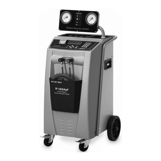
- Page 1 AirConServiceCenter VAS 581 001A Air conditioning service unit Operating manual...
- Page 2 © 2020 Dometic Group. The visual appearance of the contents of this manual is protected by copyright and design law. The underlying technical design and the products contained herein may be protected by design, patent or be patent pending. The trademarks mentioned in this manual belong to Dometic Sweden AB. All rights are reserved.
-
Page 3: Table Of Contents
VAS 581 001A Contents About this operating manual......5 Hotline ........... 5 Explanation of symbols in this operating manual. - Page 4 VAS 581 001A Operation......... . .30 Shutdown in case of repair, emergencies and malfunctions .
-
Page 5: About This Operating Manual
VAS 581 001A About this operating manual About this operating manual This operating manual describes the VAS 581 001A air conditioning service station (AirConServiceCenter). This manual is for those who perform maintenance on vehicle air conditioning systems and have the expertise required to do so. It contains all the instructions necessary for safe and effective operation of the AirConServiceCenters. -
Page 6: Explanation Of Symbols In This Operating Manual
About this operating manual VAS 581 001A Explanation of symbols in this operating manual WARNING! Safety instruction: Failure to observe this instruction can cause fatal or serious injury. CAUTION! Safety instruction: Failure to observe this instruction can lead to injury. NOTICE! Failure to observe this instruction can cause material damage and impair the function of the product. -
Page 7: Safety
VAS 581 001A Safety Safety The manufacturer will not be held liable for claims for damage resulting from the following: Faulty assembly or connection Damage to the unit resulting from mechanical influences and excess voltage Alterations to the product without the express permission of the manufacturer ... -
Page 8: Operating The Device Safely
Safety VAS 581 001A Operating the device safely WARNING! Do not operate the AirConServiceCenter in areas where there is a risk of explosion (for example, battery charging rooms or spraying booths), see operating safety directive BGR 157/TRG 250, 280, 316. ... -
Page 9: Handling Refrigerant Safely
VAS 581 001A Safety NOTICE! Never expose the unit to heavy moisture. Do not operate the unit outdoors when it is raining. Do not operate the unit near heat sources (such as heaters) or in direct sunlight. ... -
Page 10: Operational Measures When Using The Unit
Safety VAS 581 001A It also avoids the difficulty or impossibility of detecting leaks in the vehicle or in the unit due to the presence of refrigerant in the vicinity of the AirConServiceCenter. Take suitable precautions to ensure that leaking refrigerant is not able to get into the drainage system. -
Page 11: Warnings On The Airconservicecenter
VAS 581 001A Safety Warnings on the AirConServiceCenter Please note! Observe the operating manual! Only connect the device to a socket with 230 V/50 Hz AC. Protect the device against rain. Wear gloves when handling refrigerants. Wear goggles when handling refrigerants. Trained personnel! Safety devices ... -
Page 12: Scope Of Delivery
Scope of delivery VAS 581 001A Scope of delivery The AirConServiceCenter and its accessories are carefully checked before shipping. The AirConServiceCenter was tested for leaks before shipping. After delivery, check that all the parts listed below are present and undamaged. If any parts are missing or damaged, notify the company responsible for transport immediately. -
Page 13: Accessories
VAS 581 001A Accessories Accessories Available as accessories (not included in the scope of delivery): Designation Ref. number Waste oil receptacle 500 ml 4440600131 Replacement filter with filter code for maintenance 4445900221 Protective device cover 4445900081 Spare printer roll (thermal paper) (VPE 4) 4445900088 Safety goggles 8885400066... -
Page 14: Overview Of The Airconservicecenter
Overview of the AirConServiceCenter VAS 581 001A Overview of the AirConServiceCenter Front Low pressure gage Red “Fill” lamp Blue “Evacuate” lamp Yellow “ECO deep emptying” lamp Green “Suction” lamp High pressure gage Display Keypad Gas analysis unit 10 Front cover... -
Page 15: Rear And Side View
VAS 581 001A Overview of the AirConServiceCenter 11 Front wheels with wheel stops 12 Service hose for low pressure connection (blue) 13 Service hose for high pressure connection (red) 14 Service coupling for high pressure connection (red) 15 Service coupling for low pressure connection (blue) 16 Printer 17 USB port 18 Display unit... -
Page 16: Initial Startup
3. To switch it on, set the main switch (23) to I. The switch-on delay runs for 35 seconds and the housing is venti- lated. The software version number then appears in the display (7) for several seconds: Dometic Waeco Int. VA5k0048 581 001A ldyf1701... -
Page 17: Standby Menu
VAS 581 001A Initial startup ✓ Afterwards the AirConServiceCenter runs a software test. Software test. Please wait ✓ Afterwards a leak test is performed. Tightness test Please wait ✓ When the start-up procedure is complete, the AirConServiceCenter displays the standby menu: Refrigerant XXXX PAG oil... -
Page 18: Language Selection
Initial startup VAS 581 001A Language selection 1. Press cursor keys or to return to the basic menu. 2. In the basic menu, use the cursor keys or to select “Other selections”: Short selection Free selection Other selections ENTER-OK 3. -
Page 19: Adjusting The Buzzer Audio Volume
VAS 581 001A Initial startup Adjusting the buzzer audio volume 1. Press cursor keys or to return to the basic menu. 2. In the basic menu, use the cursor keys or to select “Other selections”: Short selection Free selection Other selections ENTER-OK... -
Page 20: Entering Company Data
Initial startup VAS 581 001A Entering company data The company data is printed out with every service log. 1. In the basic menu, use the cursor keys or to select “Other selections”: Short selection Free selection Other selections ENTER-OK 2. -
Page 21: Entering The Date And Time
VAS 581 001A Initial startup Entering the date and time The date and the time are printed along with the company data on every service log. 1. In the basic menu, use the cursor keys or to select “Other selections”: Short selection Free selection... -
Page 22: Editing Default Values
Initial startup VAS 581 001A Editing default values The AirConServiceCenter has preset values for the most important service tasks. The default values appear automatically when you select the respective menu. You can alter the following default values if necessary: Parameter Default value Pressure increase Test time min. -
Page 23: Inserting The Containers For Oil And Uv Additive
VAS 581 001A Initial startup 7.10 Inserting the containers for oil and UV additive NOTE Only use approved oils and UV additives for R-1234yf. Observe the manufacturer's instructions. The current supply quantities are displayed in the standby menu. 1. Open the cover flap (22) on the left side and push the containers into the snap locks: –... -
Page 24: Entering The Container Size
Initial startup VAS 581 001A 7.11 Entering the container size Fresh oil and UV contrast agent can be kept in containers of 150 ml (A), 250 ml (B) or 500 ml (C) (accessories). You must enter the size of the container in the AirConServiceCenter. -
Page 25: Analyzing Refrigerant
VAS 581 001A Initial startup 7.12 Analyzing refrigerant NOTE The AirConServiceCenter analyzes the purity level of the refrigerant before draining. If it is below 95 %, the unit does not accept the refrigerant. Each time before draining the vehicle or filling the internal refrigerant vessel, the refrigerant analysis starts automatically. - Page 26 Initial startup VAS 581 001A 7.12.2 Refrigerant analysis failed If the refrigerant fails the analysis, the AirConServiceCenter displays the following: Refrigerant Test Fail Try again? ENTER-OK 1. Confirm “Try again” with ENTER. The AirConServiceCenter checks up to three times. If the third analysis is still not successful, the AirConServiceCenter displays the following: WARNING ! Bad refrigerant!
-
Page 27: Verifying The Analysis Unit
VAS 581 001A Initial startup 7.13 Verifying the analysis unit This step uses fresh R-1234yf to test whether the analysis unit of the AirConServiceCenter is working properly. 1. Connect the AirConServiceCenter to a new refrigerant vessel with R-1234yf for verifying and then carry out the analysis, see figure: Connect the AirCon Service Center for verifying to a new refrigerant tank with R-1234yf 1. -
Page 28: Filling Up The Internal Refrigerant Container
Initial startup VAS 581 001A 7.14 Filling up the internal refrigerant container NOTE The AirConServiceCenter analyzes the purity level of the refrigerant. If it is below 95 %, the unit does not accept the refrigerant. The contami- nated mixture must be disposed of externally. When the AirConServiceCenter is started for the first time, the internal refrigerant vessel must be filled from an external refrigerant vessel with at least 2,000 g of refrigerant. - Page 29 VAS 581 001A Initial startup Int. vessel filling Flushing Reset scales. Service. 4. Press ENTER to confirm. 5. Then follow the instructions on the display and here. Connect the HP hose to the external tank then open the valve ENTER-OK STOP-EXIT Press ENTER to confirm.
-
Page 30: Operation
Operation VAS 581 001A Operation NOTICE! When the air conditioning is serviced, the engine and the air conditioning must be switched off. Shutdown in case of repair, emergencies and malfunctions 1. To ensure that the device is disconnected from the power supply for repairs, switch it off using the main switch and also pull out the power plug. - Page 31 VAS 581 001A Operation 1. First fit the service hoses for the AirConServiceCenter to the vehicle air conditioning system, and open the service couplings. 2. Press cursor key or to return to the basic menu. 3. In the basic menu, use the cursor keys or to select “Short selection”: Short selection Free selection...
-
Page 32: User Codes
Operation VAS 581 001A User codes It is possible to protect the air conditioning service station against unauthorized access using personal user codes. If the function is activated, the user code is requested after switching on. Without the code, the station can not be started up. Up to 10 different users can be created with individual codes. - Page 33 VAS 581 001A Operation 7. Confirm administrator code: ADM AREA Confirm new code ---- 8. Use the cursor keys or to select the respective user. ADM AREA User number 9. Create the four-digit personal user code (once a code is created here, the unit can then only be operated using this code).
- Page 34 Operation VAS 581 001A 8.3.2 Entering a user code When you switch on the air conditioning service station, the unit data appears in the display. If user codes have been created, a code must now be entered to enable the station. 1.
-
Page 35: Creating A Personal Database
VAS 581 001A Operation Creating a personal database Up to 100 customer-specific vehicles with the associated fill capacities can be created in this database. 1. In the basic menu, use the cursor keys or to select “Short selection”: Short selection Free selection Other selections... - Page 36 Operation VAS 581 001A 9. Enter the refrigerant fill capacity and confirm with ENTER. AUDI A4 (8E) 2000–2004 ✓ The entry has been created. AUDI A4 (8E) You can now create another entry (select with the cursor keys, then continue as described) or leave the menu using the “STOP” button. The personal entries are saved on the board, not on the flash mem- ory card.
-
Page 37: Transferring The Consumption Of Refrigerant Onto A Usb Stick
VAS 581 001A Operation Transferring the consumption of refrigerant onto a USB stick Each time a suction or filling process (single process or fully automatic) is completed, the station stores all the data in the internal memory. A report can be generated using this data and transferred to a USB stick. NOTE The USB stick must be formatted with the FAT32 file system. - Page 38 Operation VAS 581 001A 8.5.2 Manual reports You can transfer a monthly or annual report onto a USB stick manually anytime. 1. Insert the USB stick in the USB port (17). 2. In the basic menu, use the cursor keys or to select “Other selections”: Short selection Free selection...
-
Page 39: Displaying Refrigerant Consumption
VAS 581 001A Operation Displaying refrigerant consumption The station stores the data of the filled and extracted refrigerant quanti- ties. These can be printed out directly as an annual overview or monthly overview. 1. In the basic menu, use the cursor keys or to select “Other selections”: Short selection Free selection... - Page 40 Operation VAS 581 001A Example R1234 from system Total 2017 18650 PRINT STOP-EXIT “R1234 from system” shows the quantity of refrigerant extracted. Here a total of 18,650 g of refrigerant was extracted by the station in 2017. With the cursor key the total amount of refrigerant filled for the corresponding year is displayed next: R1234 to system Total...
-
Page 41: Free Selection
VAS 581 001A Operation Free selection NOTE The “Free selection” menu is used to conduct air conditioning servic- ing step-by-step. You can perform the same processes as in the short selection menu, but also omit individual procedures. In addition, it is possible to enter the values for each individual process using the keypad. - Page 42 Operation VAS 581 001A 8.7.1 Extraction process 1. Select desired settings and press ENTER to confirm. Rec/Recycling phase? ENTER-OK STOP-EXIT 2. If “Rec/Recycling phase” has been selected, enter the preferred waiting time for the pressure increase (standard is 1 min.) in the following menu and press ENTER to confirm, otherwise continue with chapter “Vacuum process”...
- Page 43 VAS 581 001A Operation 8.7.3 Filling process 1. Select desired settings and press ENTER to confirm. Filling phase? ENTER-OK STOP-EXIT 2. If “Filling phase” has been selected, enter the desired values, otherwise continue with chapter “Selecting connections” on page 44. 3.
- Page 44 Operation VAS 581 001A 8.7.4 Selecting connections 1. Select parameters according to the existing connections of the air conditioning system: – Air conditioning system has a high pressure and a low pressure connection: Select LP/HP. – Air conditioning system only has a high pressure connection: Select HP.
-
Page 45: Flushing The Air Conditioning System
VAS 581 001A Operation Flushing the air conditioning system NOTE The “Flushing” menu is used to flush the vehicle air conditioning system with fresh refrigerant. Flushing is especially suitable for replacing old compressor oil or removing most metallic residue from the system. - Page 46 Operation VAS 581 001A 11. Disconnect the system components which cannot be flushed from the refrigerant circuit. These components include: – Compressor – Line filter – Fixed choke – Collection container – Filter dryer – Expansion valve 12. Connect the components for flushing to the service ports (14) and (15) of the AirConServiceCenter using special adapters and in accordance with the manufacturer's specifications to form a flushing circuit.
- Page 47 VAS 581 001A Operation 20. Before working on the vehicle air conditioner, a leak inspection must be carried out. For the flushing process, the flushing circuit is filled with a sample filling of refrigerant. The pressure in the air conditioner must remain constant over a period of 5 minutes.
-
Page 48: Service Tasks
Service tasks VAS 581 001A 33. Screw the valve caps onto the connections of the vehicle air conditioning system. Service tasks Leak test Check the AirConServiceCenter once a year for leaks in accordance with the applicable legal requirements. Use an electronic leak detector for this purpose. - Page 49 VAS 581 001A Service tasks 4. To check the zero point of the scales for oil and UV additive, open the cover (22) on the left side and take the containers off the catches: – Container for fresh oil (19) –...
-
Page 50: Changing The Dryer Filter
Service tasks VAS 581 001A Changing the dryer filter 1. In the basic menu, use the cursor keys or to select “Free selection”: Short selection Free selection Other selections ENTER-OK 2. Press ENTER to confirm. 3. Skip the query requesting “Car data”. 4. - Page 51 VAS 581 001A Service tasks The following steps may only be performed by qualified personnel. Wear protective gloves and goggles. 12. Unscrew the screw (D) from the holder, and pull the dryer filter straight out. 13. Replace the O-rings (E). Moisten new O-rings with refrigerant oil before installing.
-
Page 52: Filter Maintenance
Service tasks VAS 581 001A Filter maintenance NOTE After finishing the service tasks, you must delete the respective service messages (counter reset). To do this, switch to “Other selections” – “Service” and enter the code “7782”. Use the cursor keys or to select the required entry and press ENTER to confirm. -
Page 53: Calibrating The Pressure Transducer
VAS 581 001A Service tasks “Service completed” displays the amount of service work performed using the air conditioning service unit since the last reset (see date). 9.4.1 Entering the filter code To reset the filter counter, you need to enter a 12-digit code. This special code is located on the new filter. - Page 54 Service tasks VAS 581 001A 8. Then follow the instructions in the display. – Unscrew the service couplings (14) and (15) from the service hoses (12) and (13). – Use the keypad (8) to enter the current local atmospheric pressure and press ENTER to confirm.
-
Page 55: Changing The Vacuum Pump Oil
VAS 581 001A Service tasks Changing the vacuum pump oil WARNING! Danger of fatal electric shock Touching uninsulated parts may result in serious injury. Switch off the AirConServiceCenter and unplug it from the power supply before opening the housing. The AirConServiceCenter may only be repaired by personnel authorized by Dometic. - Page 56 Service tasks VAS 581 001A 3. Place a receptacle with a capacity of at least ½ liter under the AirConServiceCenter. The oil from the vacuum pump flows through the opening (I) in the base of the device. 4. Unscrew the oil filling plug (G). 5.
- Page 57 VAS 581 001A Service tasks R1234 from tank 07/03/17 3395 STOP-EXIT “R1234 from tank” indicates how many grams of refrigerant were added to the unit using the menu item “Int. vessel filling”. R1234 to system 07/03/17 1200 STOP-EXIT “R1234 to system” indicates how many grams of refrigerant have been filled into air conditioning systems using the menu item “Short selec- tion”...
-
Page 58: Meter Readings
Service tasks VAS 581 001A Meter readings NOTE The unit saves various meter readings. To access the total values – consecutively, since the unit was produced – enter the menu “Other selections” – “Service” and enter the code “7783”. Use the cursor keys ... -
Page 59: Filling Level Correction For Longer Service Hoses
VAS 581 001A Service tasks Service performed: 03/07/17 STOP-EXIT “Service completed” displays the amount of service work performed using the air conditioning service unit since the last reset (see date). Filling level correction for longer service hoses NOTE If longer or shorter service hoses are required for the device, you need to adjust the filling quantities to the new hose lengths. -
Page 60: Updating The Software Via Usb
Service tasks VAS 581 001A Updating the software via USB The software is updated using a USB stick. NOTE The USB stick must be formatted with the FAT32 file system. When updating the software, the following data is stored in the internal memory of the station: ... -
Page 61: Replacing The Printer Paper
VAS 581 001A Service tasks 3. Press ENTER to update the software or database. ✓ The station shows the progress of the update: Wait... Erase flash... Erased! Writing 63488 762751 After the update, the station sets the default settings: Wait! loading default parameters The station then restarts and the standby menu appears. -
Page 62: Changing The Drained Oil Receptacle
Service tasks VAS 581 001A 9.11 Changing the drained oil receptacle NOTE Replace the drained oil receptacle and the O-ring in the lid every 6 months. If the used oil container is damaged, replace it immediately. The used oil container (21) is tight even with negative and positive pressure. -
Page 63: Cleaning And Maintenance
VAS 581 001A Service tasks 3. Replace the drained oil receptacle (O) and the O-ring (P). 4. When putting on the cover (N), pay attention to correct positioning of the tab (Q). 5. Attach the used oil container to the snap lock. 9.12 Cleaning and maintenance ... -
Page 64: Disposal
Disposal VAS 581 001A Disposal NOTICE! Protect the environment! All operating fluids and components may only be disposed of by qualified personnel in accordance with national regulations. 10.1 Disposing of used fluids Used oil is hazardous waste. Do not mix used oil with other fluids. ... -
Page 65: What To Do, When
VAS 581 001A What to do, when? What to do, when? Fault Cause Solution The display shows This message is normal To continue, press ENTER during the recycling process. for three seconds. “Warning! Internal vessel over- If this message appears pressure”... - Page 66 What to do, when? VAS 581 001A Fault Cause Solution The display shows This message appears Fill the UV additive container. during the filling process if “Not enough UV. Add!” there is not enough UV addi- tive in the container to finish the process.
- Page 67 VAS 581 001A What to do, when? Fault Cause Solution The display shows Low pressure connection not Connect low pressure hose connected to the rinsing con- to the rinse box and open “Error 09” tainer during the rinsing pro- valve. cess.
- Page 68 What to do, when? VAS 581 001A Fault Cause Solution The display shows Pressure drop during leak Check device for leaks. test. “Error 30” The display shows Residual pressure in the air Drain and evacuate. conditioning system. “Error 35” The display shows Pressure drop during pres- Check air conditioning sys- sure test.
- Page 69 VAS 581 001A What to do, when? Fault Cause Solution The display shows The readings are excessively Keep possible electrical high. sources of interference, such “00002” as mobile phones or welding equipment, away from the device. The display shows Calibration with the ambient Ensure the device is ade- air failed.
-
Page 70: Technical Data
Technical data VAS 581 001A Technical data AirConServiceCenter VAS 581 001A Reference number: ASE 581 001 01 000 Dimensions (width x height x depth): 560 mm x 1,300 mm x 650 mm Weight: 100 kg Power supply: 230 V/240 V – 50 Hz/60 Hz Refrigerant extraction rate: 30 kg / hr Vacuum pump output:... - Page 71 VAS 581 001A Technical data 12.1 Flow chart 3&...
- Page 72 Technical data VAS 581 001A Item Description UV container Fresh oil container Oil separator / heat exchanger Used oil container Refrigerant tank Compressor oil separator Analysis oil separator Compressor EXT1 External connection Coarse filter Dryer filter Gas analysis LP service coupling Service coupling, high-pressure Service hose, low-pressure LE supply line...
- Page 73 VAS 581 001A Technical data Item Description Pressure transducer Vacuum sensor Refrigerant tank return valve Capillary tube Capillary tube Klixon Temperature sensor TZH1 Temperature fuse Expansion valve Pressure reducer High-pressure safety valve High-pressure safety valve Condenser LP solenoid valve VC solenoid valve Z1 solenoid valve CY solenoid valve VO solenoid valve...
- Page 74 Technical data VAS 581 001A 12.2 Electrical circuit diagram...
- Page 75 VAS 581 001A Technical data...
- Page 76 Mail: info@dometic.be +39 0543 754983 +351 219 243 206 +41 44 8187191 Mail: vendite@dometic.it Mail: info@dometic.pt Mail: info@dometic.ch CHINA Dometic Waeco Trading – JAPAN RUSSIA UNITED ARAB EMIRATES Shanghai Branch Dometic RUS LLC Dometic Middle East FZCO Dometic KK A707–709, SOHO Zhongshan Maekawa-Shibaura, Bldg.
Need help?
Do you have a question about the AirCon ServiceCenter and is the answer not in the manual?
Questions and answers