Table of Contents
Advertisement
Quick Links
Atop Technologies Inc.
Industrial Serial Server
Industrial Modbus Gateway
Industrial Modbus Concentrator
Industrial Protocol Gateway
SE5916/MB5916/PG5916
SE5908/MB5908/PG5908
Hardware Installation Guide
Version 1.0
Updated in August, 2016
Tel: 886-3-5508137
Fax: 886-3-5508131
www.atop.com.tw
www.atoponline.com
P/N:89900499G
Package Check List
Check whether your package contains following items:
Industrail Serial Server x 1 or
Industrial Modbus Gateway x 1 or
Industrial Modbus Concentrator x 1 or
Industrial Protocol Gateway x 1
Hardware Installation Guide with Warranty Card
3-Pin 5.08mm Terminal Block
3-Pin 5.08mm Lockable Terminal Block (DC models only)
RJ-45 to Male DB9 cable
AC Power Cord (EU / US models only)
Foot Rubbers
Rack Mount Kit
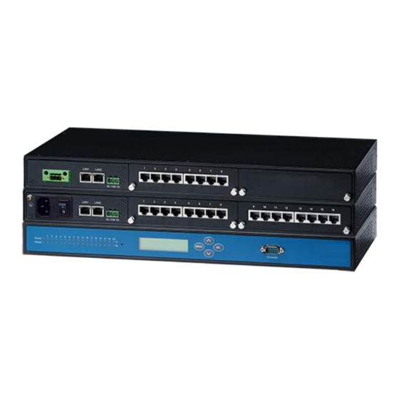
Panel Layout
*SE/MB/PG5908A has its serial ports 9-16 covered up compared to
SE/MB/PG5916
LCM Display
Buttons
Function
Open Main Menu or go back one level higher
Scroll up
Scroll down
Confirm the selection. When working with IP
addresses, pressing <SEL> means moving to the
next digit
Installation Overview
1. Ground the device properly. If you are using the AC model,
you can use the grounding screw next to the AC inlet. Else,
if you are using the DC model, you can use the FG pin in the
terminal block. It is required to connect to the grounds at all
times to ensure overall maximum performance.
2. If you opt to place the device on a rack, your will need to
secure the rack mounts kit on to the device before placing it
on the rack. If you opt to place the device on a surface, you
can put on the foot rubbers to prevent the device from
sliding.
3. You can then choose whether to plug in the I/O ports at this
point or do it later. Next you can then proceed to connect the
device to the LAN (switch or PC), take care on using the
RJ-45 connector; after this proceed to the device's settings.
The openings to the sides are for the devices heat
dissipation. Please never obstruct or cover them with any
objects.
The device server's factory IP by default is 10.0.50.100. You
can access the device by its WebUI once it is connected to a
physical network or use Serial Manager, for more
information on Serial Manger, please refer to the user
manual. Please be aware that the PC needed for this
procedure needs to be in the same subnet, or you may refer
yourself to the device's manual on Web UI configuration.
Pin Assignments
Serial and RJ-45 Connectors
Ethernet
RS-232
Pin 1
Tx+
RTS
(1)
Pin 2
Tx-
DTR
Pin 3
Rx+
TXD
Pin 4
-
SG
Pin 5
-
SG
Pin 6
Rx-
RXD
(1)
Pin 7
-
DSR
Pin 8
-
CTS
(1)
The isolated models do not have DTR/DSR available.
RS-422
2-Wire
/4-Wire
RS-485
RS-485
-
-
TX-
-
TX+
-
SG
SG
SG
SG
RX+
Data+
RX-
Data-
-
-
Advertisement
Table of Contents

Related Manuals for Atop SE5916


Summary of Contents for Atop SE5916
- Page 1 DC model, you can use the FG pin in the Industrial Modbus Concentrator x 1 or terminal block. It is required to connect to the grounds at all Atop Technologies Inc. Industrial Protocol Gateway x 1 times to ensure overall maximum performance.
- Page 2 After 3 months and still within the warranty period, it is up to 10Mbps or Disconnected Atop whether to replace the unit with a new one; normally, as 2. Please report the defected problems via Atop’s Web site or long as a product is under warranty, all parts and labor are...
Need help?
Do you have a question about the SE5916 and is the answer not in the manual?
Questions and answers