
Subscribe to Our Youtube Channel
Related Manuals for Atop SE5001


Summary of Contents for Atop SE5001
- Page 1 SE5001 Serial Device Server User’s Manual Version 1.7 April 2017 Tel: 886-3-5508137 Fax: 886-3-5508131 http://www.atop.com.tw...
-
Page 2: Important Announcement
The information contained in this document is the property of Atop Technologies, Inc. and is supplied for the sole purpose of the operation and maintenance of products of Atop Technologies, Inc. No part of this publication is to be used for any other purposes, and it is not to be reproduced, copied, disclosed, transmitted, stored in a retrieval system, or translated into any human or computer language, in any form, by any means, in whole or in part, without the prior express written consent of Atop Technologies, Inc. - Page 3 For detail information and operations of the product, please refer to the manual in the CD attached. FCC WARNING Class A for Serial Device Server (Model SE5001) This equipment has been tested and found to comply with the limits for a Class A digital device pursuant to Part 15 of the FCC rules.
-
Page 4: Table Of Contents
Security Setup ....................29 3.3.4. Backup EEPROM to Flash ................30 3.3.5. Link Mode Configuration ................30 3.3.6. Link Mode: Configure SE5001 as a TCP Server ..........31 Copyright © 2017 Atop Technologies, Inc. All rights reserved. Designed in Taiwan. - Page 5 TCP Client Application: Enable Virtual COM ..........35 3.3.12. TCP Client Application: Enable RFC 2217 ..........36 3.3.13. TCP Server Application: Configure SE5001 as a Pair Connection Master . 37 3.3.14. TCP Client Application: Configure SE5001 as a Pair Connection Slave ..37 3.3.15.
- Page 6 Interface ........................ 78 Functions ......................79 D.3.1 Device Search ....................79 D.3.2 Firmware ....................... 82 D.3.3 Configuration ....................84 D.3.4 Security ......................92 D.3.5 Virtual COM ....................94 Copyright © 2017 Atop Technologies, Inc. All rights reserved. Designed in Taiwan.
-
Page 7: Introduction
PC to fetch serial data from SE5001 remotely over the Ethernet. With SE5001, it is possible to communicate with a remote serial device in the LAN or even in the Internet, which increases the communication distance and scalability dramatically. -
Page 8: Application Connectivity
1.3 Application Connectivity TCP Server Mode: SE5001 can be configured as a TCP server in TCP/IP Network to listen for an incoming TCP client connection to the serial device. After the connection is established between the serial device server and the host computer, data can be transmitted in both directions. This also applies to Virtual COM running in the server mode. - Page 9 UDP is a faster but connectionless network protocol. It does not guarantee the delivery of network datagrams. SE5001 can be configured to transfer data using unicast or multicast UDP from the serial device to one or multiple host computers. Data can be transmitted between serial device and host computer in both directions.
- Page 10 SE5001s can be pair together (pair connection) to communicate over TCP or UDP transparently. The serial device would be unaware of the change in the communication medium. Figure 1.1 Tunneling Mode Copyright © 2017 Atop Technologies, Inc. All rights reserved. Designed in Taiwan.
-
Page 11: Hardware Installation
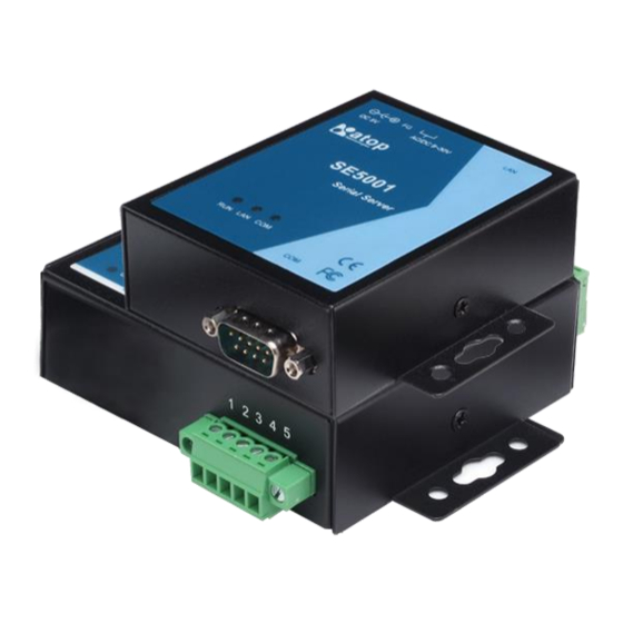
Figure 2.1 SE5001 Interfaces 2.1 Installation Procedure Step 1: Connect SE5001 to a power source using its 5V DC Jack or its 9-30V DC Terminal Block. Note that the DC Jack is 5V only and should be used with a power adaptor. - Page 12 The casing could become too hot to touch when operating in harsh environments. Please handle with care. Attention This product is intended to be grounded properly. Please do so via the Frame Ground. Copyright © 2017 Atop Technologies, Inc. All rights reserved. Designed in Taiwan.
-
Page 13: Software Setup
User Manual Version 1.7 SE5001 Serial Device Server 3. Software Setup SE5001 Ethernet Serial device server is shipped with default settings shown in the following table: Property Default Value IP Address 10.0.50.100 Gateway 10.0.0.254 Subnet Mask 255.255.0.0 User Name admin... -
Page 14: Auto Ip (Dynamic Ip)
Figure 3.2 Static IP setup dialog window 3.1.2. Auto IP (Dynamic IP) A DHCP server can automatically assign an IP address and network settings to SE5001. By default, the DHCP function in SE5001 is disabled. Use Device Management Utility to enable the DHCP function. -
Page 15: Configuration By Telnet Utility
->Open MS-DOS command prompt window or any other telnet application ->Telnet to SE5001 using command “telnet IP_address”. (For example : ”telnet 10.0.50.100” in MS-DOS command prompt window). After telnet into SE5001, system will prompt for a password, the default password is “default”. (Figure 3.4) Figure 3.4 Login to the system... - Page 16 ->Select “1” from “Input choice and enter (0~4):” to enter “Overview” (Figure 3.6): Figure 3.6 Overview This page gives one the general information of SE5001 including IP and MAC address, SNMP information, kernel and AP version, and connection status of the device.
-
Page 17: Networking
Please note that any changes made on this page won’t take effect until the device is restarted. Note: Press “ESC” key to return to the previous menu. Copyright © 2017 Atop Technologies, Inc. All rights reserved. Designed in Taiwan. -
Page 18: Change The Password
Figure 3.9 Com1 setup This page includes the option to configure different COM1 parameters, including link mode, serial port settings, serial buffer, packet delimiter, and advanced control commands. Copyright © 2017 Atop Technologies, Inc. All rights reserved. Designed in Taiwan. -
Page 19: Configure Se5001 As Tcp Server
User Manual Version 1.7 SE5001 Serial Device Server 3.2.5. Configure SE5001 as TCP server Figure 3.10 Link Mode: TCP Server Setup Type 1 (Link Mode) from “Input choice and enter (1~4):” of COM1 Type 1 (TCP Server) in the “Input choice(1~5) and enter:”... -
Page 20: Configure Se5001 As Tcp Client
SE5001 Serial Device Server 2. IP filter is disabled by default 3. If IP filter is enabled, only source IP assigned can connect to SE5001’s COM. 4. If the multi-connection firmware is installed, SE5001 will prompt for “Multi_Port”, meaning multiple connection 3.2.6. -
Page 21: Configure Se5001 As Udp
Figure 3.12 Link Mode: UDP Client Setup Type 3 in the “Input choice(1~5) and enter:“ Input SE5001’s local listening port in the “Please input local port:” Input remote device’s IP in the “Please input Destination IP:” Input remote device’s listening port in the “Please input Destination port:”... -
Page 22: Enable / Disable Pair Connection
Enable or disable “Pair Connection” on this page. For more information on how to configure two serial device servers to work in pair connection, please refer to the pair connection section 3.3.13. Copyright © 2017 Atop Technologies, Inc. All rights reserved. Designed in Taiwan. -
Page 23: Com Port Setting
(Figure 3.15). Copyright © 2017 Atop Technologies, Inc. All rights reserved. Designed in Taiwan. -
Page 24: Emptying Serial Buffer When Tcp Connection Is Established
Type 3 from “Input choice and enter (1~4):” of COM1, by default COM port serial buffer is enabled meaning that once a TCP connection is established, old serial data received from serial device before the connection will be Copyright © 2017 Atop Technologies, Inc. All rights reserved. Designed in Taiwan. -
Page 25: Setting Packet Delimiter
Ethernet packet. SE5001 provides two kinds of packet delimiter: Timer and Character. The default timer is 2 ms (0ms to disable this function). This means that if SE5001 does not receive new serial data within 2ms, it will send out all the serial data in buffer in one packet over Ethernet. The way to change the delimiter timer is shown in the following figure (Figure 3.17):... -
Page 26: Accept Control Command From Com Port
Figure 3.18 Setting Packet Delimiter: Character Pattern 3.2.13. Accept Control Command from COM port SE5001 can also accept serial control commands (RFC2217) directly from the COM port. For more detail about this function, please contact our Technical Support for more information. -
Page 27: Configuration Using Web Browser
3.3 Configuration Using Web Browser 1. Make sure the PC is located in the same network sub-net as SE5001 2. Open a web browser, then Enter in the IP address of SE5001. Default user name is admin and default password is default. - Page 28 User Manual Version 1.7 SE5001 Serial Device Server Figure 3.21 Overview Copyright © 2017 Atop Technologies, Inc. All rights reserved. Designed in Taiwan.
-
Page 29: Networking Setup
Link Up: Triggers when the TCP connection of the designated COM port is established Authentication Failure: Triggers when the username/password entered in the Telnet console or the WebUI is incorrect. Copyright © 2017 Atop Technologies, Inc. All rights reserved. Designed in Taiwan. -
Page 30: Security Setup
Figure 3.23 SNMP Setup After all the settings are entered, please click on the “Save Configuration” button to save the changes. Note that the settings would become active only after SE5001 is restarted. 3.3.3. Security Setup Change the login password on this page (Figure 3.24). -
Page 31: Backup Eeprom To Flash
This backup function could recover settings from the Flash to the EEPROM if the settings in the EEPROM are lost. If SE5001 detects that there is an EEPROM backup in the flash. It will compare the backup values in the Flash and EEPROM. -
Page 32: Link Mode: Configure Se5001 As A Tcp Server
Link Modes, TCP Server can support Virtual COM, Pair Connection, or Reverse Telnet applications. TCP Client can support Virtual COM or Pair Connection application. If none of the application is enabled, the SE5001 will run in RAW mode. In the upcoming sections, we will discuss how to setup different Link Modes properly. -
Page 33: Link Mode: Configure Se5001 As A Tcp Client
3.3.7. LINK Mode: Configure SE5001 as a TCP Client By selecting the TCP Client mode, it means that a TCP Server program should be prepared to connect to SE5001. Figure 3.27 shows all the settings provided for the TCP Client. - Page 34 TCP Keep-Alive: Specify the interval in the “Idle Time Before Sending TCP Alive Packet” to force SE5001 to send TCP Keep-Alive packets in the set interval to prevent disconnection from the client. Note that this field has a multiplier of 10, so the default value 4 means to send Keep-Alive packets every 40 seconds.
-
Page 35: Link Mode: Configure Se5001 In Udp
32 UDP nodes (baud rate 9600 bps, request interval 100ms, and data length 30bytes). Enter the Local Listening Port. This is the port that SE5001 should listen to. Match this setting in the UDP program (usually called destination port in the UDP program). -
Page 36: Tcp Server Application: Enable Rfc 2217
3.3.9 to enable Virtual COM, so that SE5001 becomes aware of the commands. Note that there is no need to configure Virtual COM on the Operating System because Virtual COM ports would not be used. 3.3.11. TCP Client Application: Enable Virtual COM It is also possible to run Virtual COM in TCP Client mode (Figure 3.30). -
Page 37: Tcp Client Application: Enable Rfc 2217
3.3.11 to enable Virtual COM, so that SE5001 becomes aware of the commands. Note that there is no need to configure Virtual COM on the Operating System because Virtual COM ports would not be used. Copyright © 2017 Atop Technologies, Inc. -
Page 38: Tcp Server Application: Configure Se5001 As A Pair Connection Master
Scroll to the bottom of the page and click on “Save Configuration” button to save the changes. Go to the Pair Connection Slave Setup below (section 3.3.14). Remember SE5001’s IP address and the Local Listening Port here in order to enter this information in the Pair Connection Slave later. -
Page 39: Tcp Server Application: Enable Reverse Telnet
3.3.15. TCP Server Application: Enable Reverse Telnet Reverse Telnet application is useful if a telnet program is used to connect to SE5001 and the serial interface of the SE5001 is connected to a Terminal Server. Telnet programs in Windows / Linux usually require special handshaking to get the outputs and formatting show properly. -
Page 40: Udp Application: Multi-Point Pair Connection
3.2.5 to configure SE5001 in TCP Server mode properly. Check Enable Pair Connection to enabled Pair Connection application in SE5001. Scroll to the bottom of the page and click on “Save Configuration” button to save the changes. 3.3.16. UDP Application: Multi-Point Pair Connection It is also possible to setup pair connection in UDP mode to have more than one Pair Connection Master or Slave to communicate to each other. -
Page 41: Tcp Server Application: Multiple Tcp Connections
3.3.17. TCP Server Application: Multiple TCP Connections To have more than one TCP Client connecting to SE5001 in TCP Server mode, contact Atop Technical Support to obtain a special multi-connection version firmware. After the firmware is uploaded to SE5001, the WebUI will have one additional option called “Multiple_Connections”... -
Page 42: Tcp Server Application: Multi-Point Tcp Pair Connections
5000 SE5001 Slave 2 10.0.50.201 TCP Client 5000 10.0.50.100 5000 SE5001 Slave 3 10.0.50.202 TCP Client 5000 10.0.50.100 5000 SE5001 Slave 4 10.0.50.203 TCP Client 5000 10.0.50.100 5000 Copyright © 2017 Atop Technologies, Inc. All rights reserved. Designed in Taiwan. -
Page 43: Com Configuration
Select one of the baudrates from the dropdown box, or select Other and then enter the desired baudrate in the input box. Baudrates higher than 230400bps are not supported. Parity / Data Bits / Stop Bits: Configure them accordingly. Flow Control: Copyright © 2017 Atop Technologies, Inc. All rights reserved. Designed in Taiwan. - Page 44 Empty Serial Buffer When TCP Connection is Established: By default, SE5001 will empty its serial buffer when a new TCP connection is established. This means that the TCP application will not receive buffered serial data during a TCP link breakage. To keep the serial data when there is no TCP connection and send out the buffered serial data immediately after a TCP connection is established, set this option to No.
- Page 45 User Manual Version 1.7 SE5001 Serial Device Server Figure 3.37 COM Configuration *For SE5001-S5, SE5001-S5-TB5 and SE5001-S5is, COM Type Selection will only show 2 Wires (RS-485) and 4 Wires (RS-422 / 4 Wire RS-485). Figure 3.38 COM Configuration Copyright © 2017 Atop Technologies, Inc.
-
Page 46: Using Virtual Com
Service Packs is required, especially for older Windows versions. To run Virtual COM in Linux, there is a separate package called TTYredirector available for download on Atop website or in the product CD. The zipped package includes a binary file for installation and a manual for Linux systems. -
Page 47: Installation
Mode configuration with Virtual COM, please refer to the previous sections starting from section 3.3.9 on Link Mode configurations. Figure 4.2 Enable Virtual COM in SE5001, SE5002, or GW series Copyright © 2017 Atop Technologies, Inc. All rights reserved. Designed in Taiwan. - Page 48 User Manual Version 1.7 SE5001 Serial Device Server Figure 4.3 Enable Virtual COM in SE540x, SW500x, or EW5302 Copyright © 2017 Atop Technologies, Inc. All rights reserved. Designed in Taiwan.
- Page 49 Figure 4.4 Enable Virtual COM in SW550x It is also possible to enable Virtual COM in serial device servers using Telnet. Please refer to the section 3.2.8 Telnet. Copyright © 2017 Atop Technologies, Inc. All rights reserved. Designed in Taiwan.
-
Page 50: Running Serial/Ip In Windows
If no Virtual COM port is selected, a dialog will pop up and asks to select at least one port as the Virtual COM port before proceeding (Figure 4.6). Figure 4.6 Select Virtual COM Ports After at least one Virtual COM port is seletected, the Control Panel will show (Figure 4.7). Copyright © 2017 Atop Technologies, Inc. All rights reserved. Designed in Taiwan. -
Page 51: Configuring Virtual Com Ports
2. If the serial device server is running in TCP Client mode, Serial/IP should be the TCP Server waiting for SE5001 to connect it. Enable Accept Connections and enter the Port Number. The Port Number here Copyright © 2017 Atop Technologies, Inc. - Page 52 Configuration Wizard window to the Control Panel, click on Use Settings. Click on Copy to copy the results to the system clipboard. 6. To transfer the settings between Virtual COM ports, click on the Copy Settings To button. Copyright © 2017 Atop Technologies, Inc. All rights reserved. Designed in Taiwan.
- Page 53 User Manual Version 1.7 SE5001 Serial Device Server Figure 4.9 Configuration Wizard Exceptions: Copyright © 2017 Atop Technologies, Inc. All rights reserved. Designed in Taiwan.
- Page 54 Figure 4.10 Virtual COM Timeout Exception a. If the exclamation mark begins with Warning: timeout trying x.x.x.x (Figure 4.10), recheck the Virtual COM IP and Port configuration or the PC’s network configuration. Copyright © 2017 Atop Technologies, Inc. All rights reserved. Designed in Taiwan.
- Page 55 If there is a check with Raw Connection Detected and an exclamation mark with Client not licensed for this server (Figure 4.11), enable Virtual COM in the serial device server. Copyright © 2017 Atop Technologies, Inc. All rights reserved. Designed in Taiwan.
- Page 56 If there is a check with Telnet Protocol Detected and an exclamation mark with Client not licensed for this server (Figure 4.12), this means that there is a licensing issue between the serial device server and Serial/IP. Please contact Atop technical support to obtain the correct Virtual COM software.
- Page 57 If the exclamation mark begins with Server requires username/password login (Figure 4.13), it means VirtualCOM Authentication in the serial device server is enabled, but credentials in the Serial/IP is not enabled. Copyright © 2017 Atop Technologies, Inc. All rights reserved. Designed in Taiwan.
- Page 58 Figure 4.14 Virtual COM Username Password Exception e. If the exclamation mark begins with Username and/or password incorrect (Figure 4.14), this means the wrong username and/or password was entered and the authentication failed. Copyright © 2017 Atop Technologies, Inc. All rights reserved. Designed in Taiwan.
-
Page 59: Using Serial/Ip Port Monitor
In the Windows notification area (Figure 4.5), right click in the Serial/IP tray icon and click on Port Monitor to open the Port Monitor. Click on the Port Monitor button in the Serial/IP Control Panel Copyright © 2017 Atop Technologies, Inc. All rights reserved. Designed in Taiwan. - Page 60 Virtual COM Port is open and is properly configured to connect to a serial device server, the status would be Connected. If Serial/IP cannot find the specified serial device server, the status would be Offline. 4.4.3. The Trace Panel Copyright © 2017 Atop Technologies, Inc. All rights reserved. Designed in Taiwan.
-
Page 61: Serial/Ip Advanced Settings
The Trace panel provides a detailed, time-stamped, real-time display of all Serial/IP COM ports operations (Figure 4.17). Click on Enable Trace to start logging Virtual COM communication. Click on File->Save As and send the log to Atop for analysis If problems arises with Virtual COM. 4.5 Serial/IP Advanced Settings In the Serial/IP Control Panel, Click on the Advanced button to open Advanced Settings window (Figure 4.18). -
Page 62: Using Serial/Ip With A Proxy Server
Enable SETXON/SETXOFF COM Port Commands This option enables additional negotiation on SETXON and SETXOFF commands and is only available for the “V” series serial device servers. If the application requires SETXON/SETXOFF feature, please contact Atop Tech Support. Figure 4.18 Serial/IP Default Advanced Settings 4.6 Using Serial/IP with a Proxy Server... - Page 63 User Manual Version 1.7 SE5001 Serial Device Server Figure 4.19 Serial/IP Proxy Settings Copyright © 2017 Atop Technologies, Inc. All rights reserved. Designed in Taiwan.
-
Page 64: Writing A Tcp Program
This sample program is written in Visual Basic 6.0 with Winsock Controls. It demonstrates how to send and receive data from a PC to SE5001 via Ethernet using two TCP sockets. Open the project file by double clicking tcptest.vbp or open it in Visual Basic (Figure 5.1). Press the Start button to launch TCPtest in debug mode. -
Page 65: Tcptest2 In Microsoft Visual C++ 6
Figure 5.2 TCP Test GUI 5.1.2 TCPTEST2 in Microsoft Visual C++ 6 To modify the program, open the project file by double clicking tcptest2.dsw or open it in Visual C++ (Figure 5.3). Copyright © 2017 Atop Technologies, Inc. All rights reserved. Designed in Taiwan. - Page 66 To run the precompiled program, open the Windows command console, switch to the folder where the executable is located (vc_ap\Release\) and enter the following commands (Figure 5.3): TCPTEST2 IP_Address Port_Number Copyright © 2017 Atop Technologies, Inc. All rights reserved. Designed in Taiwan.
- Page 67 Hello World is returned by the serial device server back to the sample program. Start with backslash (\) to send hexadecimal bytes directly. For example, \0d sends 0d. Enter “=” or use Ctrl+C to exit the program. Copyright © 2017 Atop Technologies, Inc. All rights reserved. Designed in Taiwan.
-
Page 68: Diagnostics
6.1). If the ping request cannot reach the serial device server, timed out message will show (Figure 6.2). Figure 6.1 Successful Ping Reply Figure 6.2 Ping Command Failed Copyright © 2017 Atop Technologies, Inc. All rights reserved. Designed in Taiwan. -
Page 69: Use Device Management Utility
6.2 Use Device Management Utility Use Device Management configuration utility that comes with the product CD or download from Atop website to check on the status of the serial device server. The status and version can be read from the tool. For example, ‘S’... -
Page 70: Appendix A: Specifications
5VDC Jack with Power Adaptor or DC +9-30V Terminal Block 1.5 Watt Max Temperature Operation: 0℃ to 60℃ Storage: -40℃ to 85℃ Humidity 5%~95% non-condensing Housing 65mm(L) x 78mm(W) x 28mm(H) Copyright © 2017 Atop Technologies, Inc. All rights reserved. Designed in Taiwan. -
Page 71: Software Specifications
RS-232 or RS-485/RS-422 receiving buffer size = 4K bytes RS-232 or RS-485/RS-422 transmitting buffer size = 4K bytes A.3 Panel Layout and Connector Pin Assignments A.3.1 Panel Layout A.3.1.1 SE5001 A.3.1.2 Copyright © 2017 Atop Technologies, Inc. All rights reserved. Designed in Taiwan. -
Page 72: Serial Pin Assignments
568A Definition 568B Definition Pin1 Green-White Orange-White Pin2 Green Orange Pin3 Orange-White Green-White Pin4 Blue Blue Pin5 Blue-White Blue-White Pin6 Orange Green Pin7 Brown-White Brown-White Pin8 Brown Brown Copyright © 2017 Atop Technologies, Inc. All rights reserved. Designed in Taiwan. -
Page 73: Power Terminal Block Connector
One can choose either 568A or 568B definition. If one want to make a crossover cable, one should use 568A and 568B definition respectively in each terminal of a UTP cable. A.3.4 Power Terminal Block Connector Note: Note: Reverse polarity protection is available in SE5001, so VIN+ and VIN- could be reversed. A.4 Buzzer/LED Message A.4.1 Buzzer “... -
Page 74: Run Led
Table 3. COM Port LED Message A.4.4 RUN LED Message Description LED on AP firmware is disabled LED blinking (rate: 0.5Sec) AP firmware is running Table 4. RUN LED Message Copyright © 2017 Atop Technologies, Inc. All rights reserved. Designed in Taiwan. -
Page 75: Appendix B: Upgrade System Firmware
Note: It is also possible to edit dapdl.cfg and run gwdl.exe manually without using the batch file download.bat. 5. Press any key to continue. 6. An editor will open dapdl.cfg automatically. Edit the content to match the IP address of SE5001 and the file name of the new firmware. "dapdl.cfg" has the following structure: Remote_IP 10.0.50.100... - Page 76 7. File->Save and File->Exit the text editor. 8. Enter the admin as the userid and the password of SE5001. If a password is not set, press enter. The batch file will upgrade the system firmware. SE5001 will restart automatically after the new firmware is uploaded.
-
Page 77: Error Messages
9. Repeat the process above again for kernel or AP firmware if necessary. Note: After the upgrading process finishes, SE5001 will program the flash memory and buzzer beeps 6 times then restarts. Normally, it takes around 10 seconds to complete the programming process. If an error occurs during the programming process, SE5001 will clear the corresponding memory and the system remains intact of what it was. -
Page 78: Appendix C: Disable System Firmware
SE5001 Serial Device Server Appendix C: Disable System Firmware The AP (application program) firmware of SE5001 can be disabled to restore the device to the proper firmware in case an incompatible firmware was downloaded and the system crashes while loading the AP. -
Page 79: Appendix D: Using Device Management Utility
Appendix D: Using Device Management Utility D.1 Device Management Utility Introduction Device Management Utility, the utility developed by ATOP, is a special tool for device management and configuration. It can realize the daily management of various ATOP network devices for address search, device positioning, parameter configuring, and firmware downloading. -
Page 80: Functions
D.3 Functions D.3.1 Device Search This function scans all Atop devices in the network. There are three methods to search for devices: Search by Broadcast, Search by IP Address, and Search by MAC Address. Click on “Search” in the main menu shown below to select the search method. - Page 81 Once “Search by IP Address” is selected, an interface will pop up as below. Two options are available: Select an IP address to search or Search device in the range of IP address. Copyright © 2017 Atop Technologies, Inc. All rights reserved. Designed in Taiwan.
- Page 82 If “Search by MAC Address” is selected, another box will pop up as below. There are two ways to filter the search results: “Select a MAC address to search” or “Search devices in the range of MAC address.” Copyright © 2017 Atop Technologies, Inc. All rights reserved. Designed in Taiwan.
-
Page 83: Firmware
This function is used to upload a new firmware to the device. First click on the designated device and in the main menu click Advanced->Firmware->Firmware Download or click the Upgrade from Disk button directly. Copyright © 2017 Atop Technologies, Inc. All rights reserved. Designed in Taiwan. - Page 84 Select more than one device and enable Apply for all selected devices have same model to upgrade multiple devices all at once. Copyright © 2017 Atop Technologies, Inc. All rights reserved. Designed in Taiwan.
-
Page 85: Configuration
2) Configurations can apply to multiple devices of the same kind by selecting multiple devices in the Device Management Utility and checking “Apply for all selected devices” option. Copyright © 2017 Atop Technologies, Inc. All rights reserved. Designed in Taiwan. - Page 86 Figure D.11 Network Settings Pop-up Dialog SNMP Modify the SNMP Settings of the selected device shown as the figure below. SNMP fields supported are Name, Location, and Contact. Copyright © 2017 Atop Technologies, Inc. All rights reserved. Designed in Taiwan.
- Page 87 SNMP Settings Pop-up Dialog COM Port ATOP has developed various Serial device server products. Different serial device sever could offer different COM settings. Device Management Utility could only offer the most important settings here. For the complete settings, please use the WebUI. The COM Port setting dialog is shown below.
- Page 88 Link mode: This is to setup the COM port in TCP Server, TCP Client or UDP modes. Local Port: This is the port that the COM port is listening to (TCP Server and UDP modes only). Copyright © 2017 Atop Technologies, Inc. All rights reserved. Designed in Taiwan.
- Page 89 Import the configuration file by selecting Import setting in the submenu or by clicking the Import setting button on the toolbar. The Import Settings dialog is shown below. Copyright © 2017 Atop Technologies, Inc. All rights reserved. Designed in Taiwan.
- Page 90 Export settings from the device for backup purpose or import to another device. Export the settings to a file by selecting Export setting in the submenu or clicking the Export setting button in the toolbar The Export Setting dialog is shown in the figure below. Copyright © 2017 Atop Technologies, Inc. All rights reserved. Designed in Taiwan.
- Page 91 This is the recommended way to configure the device. Select “Config by Browser” in the submenu or click on the browser button in the toolbar to launch the WebUI in the browser. A sample WebUI is shown below. Copyright © 2017 Atop Technologies, Inc. All rights reserved. Designed in Taiwan.
- Page 92 3. Select which Network Interface Card that Device Management Utility uses. If this option is set to DEFAULT, Device Management Utility will use the default NIC that the operating system assigns. Copyright © 2017 Atop Technologies, Inc. All rights reserved. Designed in Taiwan.
-
Page 93: Security
Select Login from the submenu or press the Login button in the toolbar and enter the correct password to login to the device as shown in the following figure. Note: Double clicking on the device would also login/log out from the device. Copyright © 2017 Atop Technologies, Inc. All rights reserved. Designed in Taiwan. - Page 94 Logout Pop-up Dialog Change Password Select Change Password from the submenu after a successful login to change the login password of the device as shown in the following figure. Copyright © 2017 Atop Technologies, Inc. All rights reserved. Designed in Taiwan.
-
Page 95: Virtual Com
Device Management Utility. Use this integrated Virtual COM working area or the original Serial/IP Tools to configure Virtual COM. Figure D.22 Virtual COM Confirmation Menu in Device Management Utility Select Configuration Show, a new Virtual COM Working Area would appear. Copyright © 2017 Atop Technologies, Inc. All rights reserved. Designed in Taiwan. - Page 96 Virtual COM working area by selecting “Remove devices.” Disable Virtual COM for a specific port by selecting “Port Disable”. Remember to click Apply to apply any changes. Copyright © 2017 Atop Technologies, Inc. All rights reserved. Designed in Taiwan.
- Page 97 SE5001 Serial Device Server Figure D.25 Virtual COM Right-Click Context Options Select Port Mapping to setup the Virtual COM port accordingly. Figure D.26 Virtual COM Settings Pop-up Dialog Copyright © 2017 Atop Technologies, Inc. All rights reserved. Designed in Taiwan.
Need help?
Do you have a question about the SE5001 and is the answer not in the manual?
Questions and answers