
Related Manuals for Atop SE5404D Series


Summary of Contents for Atop SE5404D Series
- Page 1 SE5404D Series 4-Port DIN-Rail Serial Device Server User’s Manual Version 1.3 May 2012 Tel: 886-3-5508137 Fax: 886-3-5508131 http://www.atop.com.tw...
- Page 2 The information contained in this document is the property of Atop Technologies, Inc. and is supplied for the sole purpose of the operation and maintenance of products of Atop Technologies, Inc. No part of this publication is to be used for any other purposes, and it is not to be reproduced, copied, disclosed, transmitted, stored in a retrieval system, or translated into any human or computer language, in any form, by any means, in whole or in part, without the prior express written consent of Atop Technologies, Inc.
- Page 3 CD or diskette. FCC WARNING Class A for Serial Device Server (Model SE5404D series) This equipment has been tested and found to comply with the limits for a Class A digital device pursuant to Part 15 of the FCC rules.
-
Page 4: Table Of Contents
........................27 YSTEM ONFIGURATION 3.2.16 Link State ............................ 27 3.2.17 Time Settings ..........................28 3.2.18 Security Settings ......................... 28 3.2.19 R ....................... 29 ESTORING ACTORY EFAULT Copyright © 2011 Atop Technologies, Inc. All rights reserved. Designed in Taiwan. - 3 -... - Page 5 3.5.8 Restore Factory Default ........................ 53 3.5.9 Restart System ..........................54 4. USING VIRTUAL COM ........................56 4.1 S ......................56 ETUP OF A VIRTUAL DRIVER Copyright © 2011 Atop Technologies, Inc. All rights reserved. Designed in Taiwan. - 4 -...
- Page 6 A.3.2.1 DB9 Pin Assignments ........................ 72 A.3.2.2 Terminal Block Pin Assignments ....................73 A.3.3.1 Ethernet Port (RJ-45) ......................... 73 A.3.4.1 Console Port (RJ-45) ........................74 A.4 Buzzer/LED Message ........................74 Copyright © 2011 Atop Technologies, Inc. All rights reserved. Designed in Taiwan. - 5 -...
- Page 7 C.3.1. Device Search ........................... 77 C.3.2. Firmware ..........................80 C.3.3. Configuration ........................... 82 C.3.4. Security ............................ 90 C.3.5. Virtual COM ..........................92 C.3.6. About ............................95 Copyright © 2011 Atop Technologies, Inc. All rights reserved. Designed in Taiwan. - 6 -...
-
Page 8: Introduction
CNC controller, etc. ATOP Technologies has overcome the limit with a family of SE5404D Series Serial Device Servers. The SE5404D sever family is designed to transmit data between one-or-more serial device and one-or-more TCP/IP device through Ethernet, and hence enhance the accessibility of the serial device through the ubiquitous TCP/IP based Ethernet. -
Page 9: Application Connectivity
(clients) in host computer to establish a connection with the serial device. After the connection is established between serial device and host computer, data can be transmitted in both directions Figure 1.1. Figure 1.1 TCP Server Mode Copyright © 2011 Atop Technologies, Inc. All rights reserved. Designed in Taiwan. - 8 -... - Page 10 After the connection is established, data can be transmitted between serial device and host computer in both directions (Figure 1.2). Figure 1.2 TCP Client Mode Copyright © 2011 Atop Technologies, Inc. All rights reserved. Designed in Taiwan. - 9 -...
- Page 11 (Figure 1.3) Vice versa is also true. Figure 1.3 UDP Mode Tunneling Mode: You can manually pair up two Atop serial servers using TCP Server and TCP Client modes and our server would transparently bridge between your serial devices.
- Page 12 User manual Version 1.3 4-Port DIN-Rail Serial Device Server SE5404D Figure 1.4 Tunneling Mode Copyright © 2011 Atop Technologies, Inc. All rights reserved. Designed in Taiwan. - 11 -...
-
Page 13: Hardware Setup
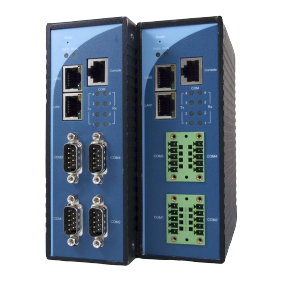
You can press the Default button of SE5404D to reset the settings to the default value Figure 2.1 Show the names of SE5404D components. Figure 2.1 Front Panel Interfaces Copyright © 2011 Atop Technologies, Inc. All rights reserved. Designed in Taiwan. - 12 -... -
Page 14: Led Indicators
Data is transmitting on Ethernet for 10Mbps Orange Blinking No data is transmitting on COM port Green Blinking Data is transmitting on COM port Green System is not ready or halt Copyright © 2011 Atop Technologies, Inc. All rights reserved. Designed in Taiwan. - 13 -... -
Page 15: Installation Procedures
The casing could become too hot to touch when operating in harsh environments. Please handle with care. RESTRICTED ACCESS AREA: The equipment should only be installed in a Restricted Access Area. Copyright © 2011 Atop Technologies, Inc. All rights reserved. Designed in Taiwan. - 14 -... -
Page 16: Software Setup
COM (1/2/3/4)Link Mode Type: TCP Server, Listen port 4660, Filter=0.0.0.0, Virtual COM disabled SysName of SNMP name SysLocation of SNMP location SysContact of SNMP contact Copyright © 2011 Atop Technologies, Inc. All rights reserved. Designed in Taiwan. - 15 -... -
Page 17: Configuration By Serial Manager Utility
By default, the DHCP client function on SE5404D is disabled; one can client use Serial Manager Utility software to search network information automatically by putting a check on Auto IP on Dialog window. (ref Figure 3.1)SE5404D (Figure 3.2) (ref Figure 3.3)SE5404D Copyright © 2011 Atop Technologies, Inc. All rights reserved. Designed in Taiwan. - 16 -... -
Page 18: Telnet Configuration
User is “admin” and password is Null (Leave it blank). Figure 3.4 System Login by Telnet Then the following main menu shall appear. Copyright © 2011 Atop Technologies, Inc. All rights reserved. Designed in Taiwan. - 17 -... -
Page 19: General Information
3.2.1 General Information Operation: Main[1]Overview This system overview window gives the general information on Ethernet, MAC address, kernel and AP version. Figure 3.6 Overview Information by Telnet Copyright © 2011 Atop Technologies, Inc. All rights reserved. Designed in Taiwan. - 18 -... -
Page 20: Networking Configuration
Enter “LAN 1 settings”, and there is all information at this section about IP address, gateway, subnet mask and IP mode (static/DHCP) of LAN 1. Figure 3.8 LAN 1 Settings by Telnet Copyright © 2011 Atop Technologies, Inc. All rights reserved. Designed in Taiwan. - 19 -... -
Page 21: Dns Settings
Serial Server to receive DNS server IP address from DHCP server automatically by enabling the DHCP of “LAN 1 Settings”. Figure 3.10 DNS Settings by Telnet Copyright © 2011 Atop Technologies, Inc. All rights reserved. Designed in Taiwan. - 20 -... -
Page 22: Snmp Settings
Figure 3.11 SNMP Settings by Telnet 3.2.6 COM Port Configuration SE5404D series allow one to configure the parameters of COM port including COM working mode, port parameters, enabling or disabling serial buffer’s data and packet delimiter setting. Figure 3.12 Select COM Port from Serial Settings by Telnet Copyright ©... -
Page 23: Tcp Server For Link Mode
On destination IP & port enter desired destination IP and port as a TCP client (For example, another serial server, or PC for data-collection). The Serial Server can support two destination host computers simultaneously. Copyright © 2011 Atop Technologies, Inc. All rights reserved. Designed in Taiwan. -
Page 24: Udp Link Mode
Serial Server can support up to 8-group IPs for UDP connection, if users needed. Figure 3.15 UDP for Link mode Note: UDP mode doesn’t support Virtual COM mode yet. Copyright © 2011 Atop Technologies, Inc. All rights reserved. Designed in Taiwan. - 23 -... -
Page 25: Serial Settings
Here one may configure baud rate, parity, data bit, stop bit, flow control, and UART mode as defined by the user. Figure 3.16 Serial Setting by Telnet 3.2.12 Alert Settings There are two subsystem settings include E-mail and Alert Event. Copyright © 2011 Atop Technologies, Inc. All rights reserved. Designed in Taiwan. - 24 -... -
Page 26: Configuring E-Mail
Figure 3.20 Configuring E-mail by Telnet One may configure Mail Server and checking on “My mail server requests authentication” field to obtain User name and Password. Copyright © 2011 Atop Technologies, Inc. All rights reserved. Designed in Taiwan. - 25 -... -
Page 27: Configuring Alert Event
Figure 3.21 Configuring Mail Server by Telnet 3.2.14 Configuring Alert Event Operation: Main [4]Alert Settings[2]Alert Event Choose the Alert event to configure SE5404D Series to send the alert notification by E-Mail or SNMP Trap (See Fig. 3.22). Figure 3.22 Configuring Alert Event by Telnet Copyright ©... -
Page 28: System Configuration
Link State is display information by Link mode (TCP Server, TCP Client and UPD) and status of each connection for all serial port. Figure 3.24 Display Link State by Telnet Copyright © 2011 Atop Technologies, Inc. All rights reserved. Designed in Taiwan. - 27 -... -
Page 29: Time Settings
3.2.18 Security Settings Operation: Main[5]System[3]Security SE5404D serials allow one to change the access methods to protect it against intrusion. Figure 3.26 Security Settings by Telnet Copyright © 2011 Atop Technologies, Inc. All rights reserved. Designed in Taiwan. - 28 -... -
Page 30: Restoring Factory Default
Choose this menu to restore Serial Server’s settings to Factory Default Settings. Figure 3.27 Restore Factory Default by Telnet 3.2.20 Restart System Operation: Main [7]Restart Choose this menu to restart the SE5404D series. Figure 3.28 Restart System by Telnet Copyright © 2011 Atop Technologies, Inc. All rights reserved. Designed in Taiwan. -
Page 31: Web Configuration
Figure 3.19 Authorization Request for System Security 3.3.2 General Information This system overview window gives the general information on Device and Network information (See Fig 3.20) Copyright © 2011 Atop Technologies, Inc. All rights reserved. Designed in Taiwan. - 30 -... - Page 32 Networking information fields are displayed both ‘LAN 1 and LAN 2’ s information on overview page. The information provided with networking settings (See Fig. 3.22). Copyright © 2011 Atop Technologies, Inc. All rights reserved. Designed in Taiwan. - 31 -...
-
Page 33: Network Configuration
Figure 3.22 Network Information by Web page 3.3.3 Network Configuration There are four items allowed to change on Network page in which include LAN 1, LAN 2, DNS and SNMP Information. Copyright © 2011 Atop Technologies, Inc. All rights reserved. Designed in Taiwan. - 32 -... -
Page 34: Lan 1 Settings
Click on the “Network” link and the following screen shall appear. Fill in LAN 1 IP information on LAN 1 TCP/IP field. Alternatively, one may activate DHCP client function by checking on “Obtain an IP automatically”. Copyright © 2011 Atop Technologies, Inc. All rights reserved. Designed in Taiwan. -
Page 35: Lan 2 Settings
Click on the “Network” link and the following screen shall appear. Fill in DNS information. Alternatively, you can set the Serial Server to receive DNS server IP address from DHCP server automatically by enabling the DHCP of “LAN 1 Settings”. Copyright © 2011 Atop Technologies, Inc. All rights reserved. Designed in Taiwan. - 34 -... -
Page 36: Snmp Settings
SNMP” field. Fill in Read Community, Write Community, SNMP Trap Server information on SNMP Settings fields. The changes of SNMP Settings will take effect immediately when saved successful. Figure 3.27 SNMP Setting by Web page Copyright © 2011 Atop Technologies, Inc. All rights reserved. Designed in Taiwan. - 35 -... -
Page 37: Com Port Configuration
SE5404D A COM1’s settings (Default Destination IP=10.10.50.100, Default Destination Port = 4660). (optional) Repeat for remaining COMs: Set SE5404D A COM2 to TCP Server mode. Set SE5404D B COM2 Copyright © 2011 Atop Technologies, Inc. All rights reserved. Designed in Taiwan. - Page 38 One may configure one or group IP for source IP. If IP filter is enabled, only source IP assigned is connected to Serial Server. If you check “Apply to all serial ports”, it will configure all of the serial ports. Copyright © 2011 Atop Technologies, Inc. All rights reserved. Designed in Taiwan. - 37 -...
-
Page 39: Tcp Client For Link Mode
(For example, another serial server, or PC for data-collection). Serial Server can support two destination hosts simultaneously. If you check “Apply to all serial ports”, it will configure all of the serial ports. Copyright © 2011 Atop Technologies, Inc. All rights reserved. Designed in Taiwan. - 38 -... -
Page 40: Udp For Link Mode
4660 which receive data sending from the host computers) Serial Server can support up to 8-group IP for UDP connection, if users needed. If you check “Apply to all serial ports”, it will configure all of the serial ports. Copyright © 2011 Atop Technologies, Inc. All rights reserved. Designed in Taiwan. - 39 -... -
Page 41: Serial Settings
FIFO should be disabled. For regular applications, we recommend to enable FIFO (default) to achieve optimal performance. If you check “Apply to all serial ports”, it will configure all of the serial ports. Copyright © 2011 Atop Technologies, Inc. All rights reserved. Designed in Taiwan. - 40 -... -
Page 42: Advanced Settings
Time out for receiving TCP data (Default: Disabled): This field specifies how long the serial device server will wait for a response to “keep alive” packets before closing the TCP connection. The serial device server checks Copyright © 2011 Atop Technologies, Inc. All rights reserved. Designed in Taiwan. - Page 43 By Character - The device will transmit the network data in its buffer when it sees the specified character. If one or more of the delimiters are selected, data would be transmitted if any of the conditions are met. Copyright © 2011 Atop Technologies, Inc. All rights reserved. Designed in Taiwan. - 42 -...
-
Page 44: Alert Settings
If “Enable” is selected, the device will store received data in buffer and sent them out when connection is establish. Otherwise, data will be discarded when “Disable” is selected. 3.4.7 Alert Settings There are two subsystem settings include E-mail and Alert Event. Copyright © 2011 Atop Technologies, Inc. All rights reserved. Designed in Taiwan. - 43 -... -
Page 45: Configuring E-Mail
E-mail notification will be sent to the e-mail account their obtained in “Receiver’s E-mail address 1”, “Receiver’s E-mail address 2”, “Receiver’s E-mail address 3”, “Receiver’s E-mail address 4” and “Receiver’s E-mail address 5”. Copyright © 2011 Atop Technologies, Inc. All rights reserved. Designed in Taiwan. -
Page 46: Configuring Alert Event
Operation: AlertAlert Event Click on the “Alert Event” link and the following screen shall appear Choose the Alert event to configure SE5404D Series to send the alert notification by E-Mail or SNMP Trap (See Fig 3.36). Copyright © 2011 Atop Technologies, Inc. -
Page 47: System Configuration
Figure 3.36 Configuring Alert Event by Web page 3.5 System Configuration There are six subsystem settings for system configuration including Link State, Time, Security, Set to Default and Restart. Copyright © 2011 Atop Technologies, Inc. All rights reserved. Designed in Taiwan. - 46 -... -
Page 48: Link State Information
Link State is display information by Link mode (TCP Server, TCP Client and UPD) and status of each connection for all serial port. Figure 3.38 Link State Information by Web page 3.5.2 Log Settings Operation: SystemLog Setting Copyright © 2011 Atop Technologies, Inc. All rights reserved. Designed in Taiwan. - 47 -... - Page 49 Enable Syslog Server: Enabling this option would allow you to send COM logs to a remote Syslog server. You can send COM logs to the same Syslog server used previously. Copyright © 2011 Atop Technologies, Inc. All rights reserved. Designed in Taiwan.
-
Page 50: System Log
Time manually” field. You can enable and specify the Daylight Saving Time if you are located in a DST region. All the settings on the page require a restart. Copyright © 2011 Atop Technologies, Inc. All rights reserved. Designed in Taiwan. -
Page 51: Security Configuration
4-Port DIN-Rail Serial Device Server SE5404D Figure 3.43 Time Settings by web page 3.5.6 Security Configuration Operation: SystemSecurity Click on the “Security” link and the following screen shall appear Copyright © 2011 Atop Technologies, Inc. All rights reserved. Designed in Taiwan. - 50 -... - Page 52 Enter the old password on “Old Password” field; enter the new password on “New Password” and the “Verified Password” fields, and then click on “Save Configuration” to update the password. Copyright © 2011 Atop Technologies, Inc. All rights reserved. Designed in Taiwan.
-
Page 53: Import/Export
3.5.7 Import/Export Operation: SystemImport/Export Please select a setting file to be imported or a file path for the settings to be exported on the WebUI. Copyright © 2011 Atop Technologies, Inc. All rights reserved. Designed in Taiwan. - 52 -... -
Page 54: Restore Factory Default
3.5.8 Restore Factory Default Operation: System Set to Default One may click on “set to default and restart” button to restore Serial Server’s settings to Factory Default Settings. Copyright © 2011 Atop Technologies, Inc. All rights reserved. Designed in Taiwan. - 53 -... -
Page 55: Restart System
Figure 3.48 Restore Factory Default by Web page 3.5.9 Restart System Operation: System Restart One may press “Restart” button to restart the SE5404D series. The web page will be refreshing after it reboot. Copyright © 2011 Atop Technologies, Inc. All rights reserved. Designed in Taiwan. - Page 56 User manual Version 1.3 4-Port DIN-Rail Serial Device Server SE5404D Figure 3.49 Restart System by Web page Copyright © 2011 Atop Technologies, Inc. All rights reserved. Designed in Taiwan. - 55 -...
-
Page 57: Using Virtual Com
The Virtual COM driver provides user to select up to 256 COM ports as Virtual COM ports in a Serial Manager Utility PC. User can select them from a list of COM ports, which is from COM1 up to COM256. Copyright © 2011 Atop Technologies, Inc. All rights reserved. Designed in Taiwan. -
Page 58: Installation
Select Serial IP in the list of installed software. Click the Add/Remove button to remove the program, or From Windows Start menu select Programs, Serial IP for ATOP, Uninstall Serial IP to remove the program. 4.2 Virtual COM communication 4.2.1 Enable Virtual COM on SE5404D From web browser access to SE5404D by typing its IP address, ... -
Page 59: Run Serial/Ip On Pc
5. Click the Configuration Wizard button and then click the Start button that appears in the wizard window. This important step verifies that the Virtual COM Redirector can communicate with the serial server using Copyright © 2011 Atop Technologies, Inc. All rights reserved. Designed in Taiwan. - Page 60 For COM Port Options, the settings must match the COM port behavior expected by the PC application that will use this COM port. The Configuration Wizard will recommend a combination of settings. Copyright © 2011 Atop Technologies, Inc. All rights reserved. Designed in Taiwan.
-
Page 61: Snmp Setup
The following screen appears, in the Addresses field, Enter in the IP address range to search(Figure 5.1). Figure 5.1 NetworkView-IP discovery parameters setup Copyright © 2011 Atop Technologies, Inc. All rights reserved. Designed in Taiwan. - 60 -... - Page 62 1. The NetworkView tool is limited to information extracting and viewing only. 2. To modify the configurations please use the web server, Telnet or Serial Manager configuration utilities. Copyright © 2011 Atop Technologies, Inc. All rights reserved. Designed in Taiwan.
-
Page 63: Start Writing Ones Own Applications
NOTE: Please be sure the Microsoft visual studio family or its equivalent software is installed on the computer. Otherwise the sample program will not run. Copyright © 2011 Atop Technologies, Inc. All rights reserved. Designed in Taiwan. - 62 -... -
Page 64: Tcptest2 In Visual C
You can also use modem to connect to the serial server. Command "AT\Od" sends standard AT command to the modem which in return responds with "OK\0D\0A" message to the host application. Always use '=' then Enter key to exit the program. Copyright © 2011 Atop Technologies, Inc. All rights reserved. Designed in Taiwan. - 63 -... -
Page 65: Diagnostics
Use Serial Manager Utility configuration program that comes with the product CD or diskette to check on the status of SE5404D. The status and version can be read from the tool. Copyright © 2011 Atop Technologies, Inc. All rights reserved. Designed in Taiwan. -
Page 66: Use Tcptest.exe Or Tcptest2.Exe Sample Program
Use sample programs TCPTEST.EXE and TCPTEST2.EXE that comes with the product CD or diskette to check on the status of SE5404D. Please refer to chapter 6.2 to run the sample programs. Copyright © 2011 Atop Technologies, Inc. All rights reserved. Designed in Taiwan. -
Page 67: Appendix A: Specifications
9-Pin lockable D-Sub Connector 5-Pin 5.08mm lockable Terminal Block Power Input 9-48DCV, 0.65A max consumption Max. 5.85W Connector 7-pin 5.08mm connector for redundant power input Copyright © 2011 Atop Technologies, Inc. All rights reserved. Designed in Taiwan. - 66 -... -
Page 68: Panel Layout And Connector Pin Assignments A.3.1. Panel Layout
Windows & Linux port redirection software Support Protocol ICMP, TCP/IP, UDP, DHCP Client, NTP, DNS, SNMP, HTTP, Telnet, SMTP A.3 Panel Layout and Connector Pin Assignments A.3.1. Panel Layout Copyright © 2011 Atop Technologies, Inc. All rights reserved. Designed in Taiwan. - 67 -... - Page 69 User manual Version 1.3 4-Port DIN-Rail Serial Device Server SE5404D A.3.1.1 SE5404D Front Panel A.3.1.2 SE5404D Side View Copyright © 2011 Atop Technologies, Inc. All rights reserved. Designed in Taiwan. - 68 -...
- Page 70 User manual Version 1.3 4-Port DIN-Rail Serial Device Server SE5404D Copyright © 2011 Atop Technologies, Inc. All rights reserved. Designed in Taiwan. - 69 -...
- Page 71 User manual Version 1.3 4-Port DIN-Rail Serial Device Server SE5404D A.3.1.3 SE5404D Top View Copyright © 2011 Atop Technologies, Inc. All rights reserved. Designed in Taiwan. - 70 -...
- Page 72 User manual Version 1.3 4-Port DIN-Rail Serial Device Server SE5404D A.3.1.4 SE5404D Rear and Mounting View Copyright © 2011 Atop Technologies, Inc. All rights reserved. Designed in Taiwan. - 71 -...
-
Page 73: Db9 Pin Assignments
Full Duplex Half Duplex Full Duplex TXD+ N/A (reserved) RXD+ DATA+ SG (Signal Ground) SG (Signal Ground) SG (Signal Ground) RXD- DATA- TXD- N/A (reserved) Copyright © 2011 Atop Technologies, Inc. All rights reserved. Designed in Taiwan. - 72 -... -
Page 74: Terminal Block Pin Assignments
1. Category 5 UTP cable, 8 core wires. 2. RJ45 Connector. 3. RJ45 Pin Assignment Pin Assignment 568A Definition 568B Definition Pin1 Green-White Orange-White Pin2 Green Orange Pin3 Orange-White Green-White Copyright © 2011 Atop Technologies, Inc. All rights reserved. Designed in Taiwan. - 73 -... -
Page 75: Console Port (Rj-45)
“ ^ “: Beep twice “ = “: Beep off Message Description ^==^========^^^ Startup OK and AP firmware is enabled (5sec.) Table 1. Buzzer Message Copyright © 2011 Atop Technologies, Inc. All rights reserved. Designed in Taiwan. - 74 -... -
Page 76: Appendix B: Upgrade System Firmware
Make sure the PC and the SE5404D series on the same network. Use command ping or Serial Manager Utility program to verify their availability. Edit “dll.bat ” to fit the system requirements, Be sure to save ones modification ... -
Page 77: Error Messages
SE5404D handshaking problem SE5404D ACK Start Address Error SE5404D ACK Length Error SE5404D Response Command Error Configuration file Remote IP not found Open configuration file failure Copyright © 2011 Atop Technologies, Inc. All rights reserved. Designed in Taiwan. - 76 -... -
Page 78: Appendix C: Using Serial Manager Utility
C.1. Serial Manager utility Introduction Serial Manager utility, developed by ATOP, is a special tool for device management and configuration. It can realize the daily management on various ATOP network devices for address search, device positioning, parameter configuring, and firmware downloading. Note that EW5302 is used to demonstrate the functionality of Serial Manager instead of SE5404D. - Page 79 Once “Broadcast Search” is selected, a box will pop up as below. The user may type in or select different broadcast address based on the requirement. Copyright © 2011 Atop Technologies, Inc. All rights reserved. Designed in Taiwan. - 78 -...
- Page 80 If “Search by MAC Address” is selected, another box will pop up as below. Here the user may search in two ways: “Search a MAC address to search” or “Search devices in the range of MAC address” Copyright © 2011 Atop Technologies, Inc. All rights reserved. Designed in Taiwan.
-
Page 81: Firmware
“Firmware Download” in the main menu option “Firmware”, or directly clicking the button Upgrade from disk. Copyright © 2011 Atop Technologies, Inc. All rights reserved. Designed in Taiwan. - 80 -... - Page 82 The user can also select several same devices at one time, and realize the firmware updating for them by selecting Apply for all selected devices have same model. Copyright © 2011 Atop Technologies, Inc. All rights reserved. Designed in Taiwan.
-
Page 83: Configuration
“Import Setting”, “Export Setting”, “Virtual COM”, “Config by browser” and “Options.” Users can carry out a configuration operating through menu or by clicking the corresponded button on the toolbar, shown as the figure below: Copyright © 2011 Atop Technologies, Inc. All rights reserved. Designed in Taiwan. - 82 -... - Page 84 The user can modify SNMP settings of any selected device, shown as the figure below. The support SNMP fields are Name, Location, and Contact. Note: This function will be enabled after a successful login. Copyright © 2011 Atop Technologies, Inc. All rights reserved. Designed in Taiwan. - 83 -...
- Page 85 4-Port DIN-Rail Serial Device Server SE5404D COM Port ATOP has developed various Serial server products, and some of the ATOP devices are specially applied to some serial-port servers, while this function is applied to the configuration of COM port parameters only. The COM Port setting dialog is shown below.
- Page 86 Each COM port corresponds to a link mode, TCP or UDP, which is used to transfer data. The user can set each link mode and the working parameters according to requirements. Copyright © 2011 Atop Technologies, Inc. All rights reserved. Designed in Taiwan.
- Page 87 Import setting or by clicking the Import setting button on the toolbar. The dialog of import parameter settings is shown below. Copyright © 2011 Atop Technologies, Inc. All rights reserved. Designed in Taiwan. - 86 -...
- Page 88 Export setting or clicking the Export setting button on the toolbar for backup purpose or to be imported to other device. The dialog of Export Setting is shown in the figure below. Copyright © 2011 Atop Technologies, Inc. All rights reserved. Designed in Taiwan.
- Page 89 Manager does not supply. Users can carry out any parameter setting directly through the submenu option “Config by Browser”, and a Web browser is shown in the figure below. Copyright © 2011 Atop Technologies, Inc. All rights reserved. Designed in Taiwan.
- Page 90 3. You can select which Network Interface Card that Serial Manager uses. If this option is set to DEFAULT, SerialManger will uses the default NIC that the operating system assigns. Copyright © 2011 Atop Technologies, Inc. All rights reserved. Designed in Taiwan.
-
Page 91: Security
“Apply for all selected devices.” Note: Double clicking on the device would also login/log out from the device. Copyright © 2011 Atop Technologies, Inc. All rights reserved. Designed in Taiwan. - 90 -... - Page 92 The user can also select several devices at one time, and modify their pins at the same time by selecting “Apply for all selected devices.” Copyright © 2011 Atop Technologies, Inc. All rights reserved. Designed in Taiwan.
-
Page 93: Virtual Com
Virtual COM working area or the original Serial/IP Tools to configure Virtual COM. After you select Configuration Show, a new Virtual COM working area would appear. Copyright © 2011 Atop Technologies, Inc. All rights reserved. Designed in Taiwan. - 92 -... - Page 94 Select the device you want to establish a Virtual COM connection with, you can select multiple devices. After the device is selected, right click in the blank working area and select “Add devices”. Copyright © 2011 Atop Technologies, Inc. All rights reserved. Designed in Taiwan.
- Page 95 Virtual COM working area by selecting “Remove devices.” You can disable Virtual COM for a specific port by selecting “Port Disable”. Remember to click Apply to apply any changes. Copyright © 2011 Atop Technologies, Inc. All rights reserved. Designed in Taiwan.
-
Page 96: About
If you select Port Mapping… , a new window would show. You can setup the Virtual COM accordingly. C.3.6. About This function is mainly applied to displaying information of the Serial Manager utility, shown in the figure below. Copyright © 2011 Atop Technologies, Inc. All rights reserved. Designed in Taiwan. - 95 -... - Page 97 User manual Version 1.3 4-Port DIN-Rail Serial Device Server SE5404D Copyright © 2011 Atop Technologies, Inc. All rights reserved. Designed in Taiwan. - 96 -...
Need help?
Do you have a question about the SE5404D Series and is the answer not in the manual?
Questions and answers