Table of Contents
Advertisement
Quick Links
Advertisement
Chapters
Table of Contents

Related Manuals for RS PRO ISA-730


Summary of Contents for RS PRO ISA-730
- Page 1 Instruction Manual ISA-730 Spectrum Analyzer...
-
Page 3: Table Of Contents
Display ............... 73 Save/Recall Files ............77 System Settings ............83 REMOTE CONTROL .................. 85 Interface Configuration ..........86 Command Syntax ............89 Command List ............. 92 FAQ......................117 APPENDIX ....................119 ISA-730 Default Settings ..........119 21/11/2016 Version No. 002... - Page 4 ISA-730 Instruction Manual/English ISA-730 Specifications ..........121 ISA-730 Dimensions ..........124 Declaration of Conformity ........... 125 INDEX ............... 126 21/11/2016 Version No. 002...
-
Page 5: Safety Instructions
SAFETY INSTRUCTIONS AFETY INSTRUCTIONS This chapter contains important safety instructions that you must follow during operation and storage. Read the following before any operation to insure your safety and to keep the instrument in the best possible condition. Safety Symbols These safety symbols may appear in this manual or on the instrument. - Page 6 ISA-730 Instruction Manual/English Frame or Chassis Terminal Do not dispose electronic equipment as unsorted municipal waste. Please use a separate collection facility or contact the supplier from which this instrument was purchased. Safety Guidelines General Guideline Do not place any heavy object on the instrument.
- Page 7 SAFETY INSTRUCTIONS Measurement category III is for measurement performed in the building installation. Measurement category II is for measurement performed on the circuits directly connected to the low voltage installation. Measurement category I is for measurements performed on circuits not directly connected to Mains.
- Page 8 ISA-730 Instruction Manual/English falls under degree 2. Pollution refers to “addition of foreign matter, solid, liquid, or gaseous (ionized gases), that may produce a reduction of dielectric strength or surface resistivity”. Pollution degree 1: No pollution or only dry, non-conductive pollution occurs.
- Page 9 SAFETY INSTRUCTIONS When using the unit in the United Kingdom, make sure the power cord meets the following safety instructions. NOTE: This lead/appliance must only be wired by competent persons WARNING: THIS APPLIANCE MUST BE EARTHED IMPORTANT: The wires in this lead are coloured in accordance with the following code: Green/ Yellow: Earth Blue:...
- Page 10 ISA-730 Instruction Manual/English ETTING STARTED This chapter provides a brief overview of the ISA-730, the package contents, instructions for first time use and an introduction to the front panel, rear panel and GUI. ISA-730 Introduction ............ 10 Main Features ................10 Package Contents ..............
-
Page 11: Getting Started
GETTING STARTED USB Driver Installation .............. 22 Restoring Default Settings ............24 Conventions ................24 21/11/2016 Version No. 002... -
Page 12: Isa-730 Introduction
ISA-730 Instruction Manual/English ISA-730 Introduction The ISA-730 is a low-cost, basic spectrum analyzer. The ISA-730 has all the basic features of our more advanced models, but in a smaller package, designed especially for education. Main Features 150kHz~3GHz bandwidth Performance ... -
Page 13: Package Contents
GETTING STARTED USB 2.0 Device port for the virtual com port communication Package Contents Check the contents before using the ISA-730. Opening the box Main unit Power cord x1 (region Contents (single dependent) Quick Start Guide unit) ... -
Page 14: Appearance
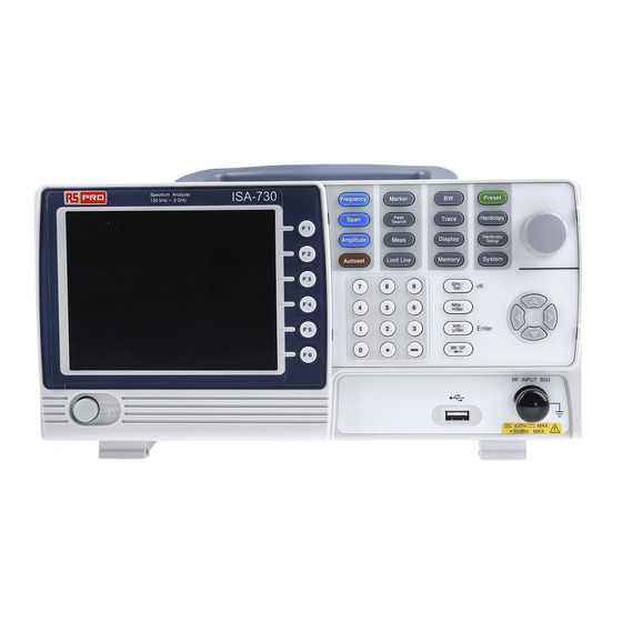
ISA-730 Instruction Manual/English Appearance ISA-730 Front Panel LCD Display Function Menu keys Hardcopy key Keys Frequency Marker Preset Peak Span Trace Hardcopy Search Scroll wheel Hardcopy Amplitude Meas Display Setup Autoset Limit Line Memory System GHz / MHz / Arrow keys... - Page 15 GETTING STARTED Span Span Sets the span, with options for full span, zero span and last span. Amplitude Amplitude Sets the amplitude reference level, scale and amplitude units. Autoset Autoset Automatically searches the peak signal with maximum amplitude and displays it with appropriate horizontal and vertical scales.
- Page 16 ISA-730 Instruction Manual/English Display Display The Display key configures the split-screen windowing mode and the basic display properties. Memory Memory The memory key is used to save or recall setup, trace and limit line data. Preset Preset Preset key will restore the spectrum analyzer to the factory settings.
- Page 17 GETTING STARTED Arrow keys Increment/decrement values (in steps), select listed items. RF INPUT 50 Ω RF input terminal RF input port. Accepts RF inputs. Maximum input: +30dBm (+20dBm measurable) DC ±25V MAX. +30dBm MAX. Input impedance: 50Ω Maximum DC voltage: ±25V ...
-
Page 18: Rear Panel
ISA-730 Instruction Manual/English Rear Panel USB B port RS232 port VGA port Security slot Power socket RS232 RS232 9 pin DSUB port. USB B USB B Device port. USB 1.1/2.0 VGA video-out port. Supports SVGA (480X640) Power Socket: Power Socket 100~240V, 50/60Hz. -
Page 19: Display
GETTING STARTED Security Slot Kensington-type security slot. Display Marker information Function menu Reference level Traces and Soft menu waveforms keys Frequency/ Bandwidth settings Entry / Message area Trace icons Reference level Displays the reference level. For details, see page 38. Marker information Displays marker information. - Page 20 ISA-730 Instruction Manual/English Trace Icons Displays the color of each active trace and the trace mode of each active trace. See page 68 for more information about traces. Entry/Message area This area is used to show system messages, errors and input values/parameters.
-
Page 21: First Time Use Instructions
GETTING STARTED First Time Use Instructions Use the procedures below when first using the ISA-730 to tilt the stand, power up the instrument, update the firmware and restore the unit back to the default settings. Lastly, the Conventions sections will introduce you to the basic operating conventions used throughout the user manual. -
Page 22: Power Up And Down
1. Insert the AC power cord into the power socket. 2. Press the power button to turn the ISA- 730 on. 3. The ISA-730 will begin to boot up in under a few seconds. If system fails to start, please see your local distributor. Note Power Down 1. - Page 23 GETTING STARTED System version Before updating the software, please check the software version. System Information[F4]. 1. Press > 2. The system version is displayed on the SW Ver[F4] icon. Software version Update software 1. Place the update file, MAIN1.BIN, into the root directory of a USB flash drive.
- Page 24 USB B port. 3. Windows will automatically detect the ISA-730 as a new device. 4. Follow the instructions to locate the ISA-730 driver on the accompanying CD and install the driver. 5. To see if the driver has been successfully installed, you...
- Page 25 GETTING STARTED can check to see if the ISA-730 is recognized by the Windows Device Manager when the ISA-730 in connected to the PC. 6. In Windows XP go to: Start>Control Panel>Device Manager. 7. The ISA-730 should be shown under the Ports (COM &...
- Page 26 Conventions The following conventions are used throughout the user manual. Read the conventions below for a basic grasp of how to operate the ISA-730 menu system and front panel keys. The F1 to F6 function keys on the right side of the display Soft Menu keys correspond directly to the soft-menu keys on their left.
- Page 27 GETTING STARTED Input Parameter Values Selecting this type of menu key will allow you to enter a new value with the numeric keypad or increment/decrement the value using the scroll wheel or number pad. See the parameter input description below for more details. Toggle State Pressing this menu key will toggle the state.
- Page 28 ISA-730 Instruction Manual/English Sub Menu More Pressing the menu key will enter a submenu. Sub Menu to select parameter Pressing this type of menu key will enter a submenu to select a parameter. Return to the Start of When you have navigated down a menu tree and you wish to a Menu Tree.
- Page 29 GETTING STARTED Scroll wheel Parameter input Numerical keypad GHz / MHz / mSec kHz / Enter µSec BK SP Directional arrow keys Backspace, Enter keys and unit keys Parameter values can be entered using the numeric keypad, the scroll wheel and the arrow keys. Using the numeric When prompted to enter a parameter, use the number keys keypad...
- Page 30 ISA-730 Instruction Manual/English Back Space Use the backspace key to delete the last character or number entered. Using the scroll Use the scroll wheel to alter the current value. Clockwise wheel increases the value, anti-clockwise decreases the value. The scroll wheel is usually used for values that are highly variable, such as the center frequency settings.
-
Page 31: Basic Operation
BASIC OPERATION ASIC OPERATION Frequency Settings ............32 Center Frequency ............... 32 Start and Stop Frequency ............32 Center Frequency Step ............... 34 Span Settings .............. 35 Span .................... 35 Full Span ..................36 Zero Span ..................36 Last Span ..................37 Amplitude Settings ............ - Page 32 ISA-730 Instruction Manual/English Activate a Normal Marker ..........44 Activate a Delta Marker ........... 45 Move Marker Manually ............ 46 Move Marker to Preset Locations ........47 Move Marker to Trace ..............48 Turn All Markers On or Off ..........49 Show Markers in Table..............
- Page 33 BASIC OPERATION Average Trace ................71 Display ............... 73 Adjusting the LCD Brightness ............. 73 Setting a Display Line (Reference Level Line) ......73 Using the Video Out Port ............74 Split Spectrum View ..............74 Save/Recall Files ............77 Save/Recall Setup ...............
-
Page 34: Frequency Settings
ISA-730 Instruction Manual/English Frequency Settings Center Frequency Description The center frequency function sets the center frequency and centers the display to the center frequency. Frequency Center[F1] Operation 1. Press > and enter the frequency and unit. Range: 0kHz~3GHz Default: 1.5GHz... - Page 35 BASIC OPERATION Start[F2] Operation 1. To set the start frequency, press Frequency > enter the frequency and unit. Stop[F3] 2. To set the stop frequency, press Frequency > enter the frequency and unit. Range: 0kHz~3GHz Default Start frequency: 3GHz Default Stop frequency: Display Start Frequency...
-
Page 36: Center Frequency Step
ISA-730 Instruction Manual/English Center Frequency Step Step Description function sets the step size of the center frequency when using the arrow keys. When the arrow keys are used to alter the center frequency, each press will move the center frequency by the step size... -
Page 37: Span Settings
BASIC OPERATION Span Settings Span Description The Span function will set the frequency range of the sweep. The sweep will be centered around the center frequency. Setting the span will alter the start and stop frequencies. Span[F1] Operation 1. Press >... -
Page 38: Full Span
ISA-730 Instruction Manual/English Full Span Description The Full Span function will set the span to the full frequency range. This function will set the start and stop frequencies to 0Hz and 3GHz respectively. Span Full Span[F2] Operation 1. Press >... -
Page 39: Last Span
BASIC OPERATION Time domain Display 0Hz Span Example: Amplitude modulation The measurement functions such as ACPR and OCBW Note are not available with the zero span setting: Last Span Description The last span function returns the spectrum analyzer to the previous span settings. -
Page 40: Amplitude Settings
ISA-730 Instruction Manual/English Amplitude Settings The vertical display scale is defined by the reference level amplitude, attenuation, scale and external gain/loss. Reference Level Description The reference level defines the absolute level of the amplitude on the top graticule in voltage or power. -
Page 41: Amplitude Units
BASIC OPERATION Amplitude Units Description The amplitude units can be set from dBm, dBmV or dBuV. Units …[F3] 1. Press Amplitude > to change the amplitude units. Units: dBm, dBmV, dBuV Scale/Div Description Sets the logarithmic units for the vertical divisions. Scale[F2] Operation 1. -
Page 42: Autoset
ISA-730 Instruction Manual/English Autoset The Autoset function searches the peak signals and picks the signal peak with the maximum amplitude, and then shows it in the display. Using Autoset Autoset Autoset[F1] Operation 1. Press > Autoset Range Amplitude: Over the full amplitude range. -
Page 43: Limiting The Autoset Vertical Search Range
BASIC OPERATION After Autoset RBW setting is reset to Auto when the Autoset function is Note used. Limiting the Autoset Vertical Search Range Description You can set the amplitude floor so that the signals lower than the setting will be ignored by the Autoset search. Amp.Floor[F2] Operation 1. -
Page 44: Limiting The Autoset Horizontal Search Range
ISA-730 Instruction Manual/English Limiting the Autoset Horizontal Search Range Description You can change the frequency span limit in the display to get a better view of the Autoset result. By default, the frequency span after Autoset is set at 3MHz. -
Page 45: Marker
BASIC OPERATION Marker A Marker shows the frequency and amplitude of a waveform point. The ISA-730 can activate up to 5 markers or marker pairs simultaneously. The marker table and peak table functions help editing and viewing multiple markers in a single display. -
Page 46: Activating A Marker
ISA-730 Instruction Manual/English Search for Peaks→ from page 52 Peak Table→ from page 53 Activating a Marker There are two basic marker types, normal markers and delta markers. Normal markers are used to measure the frequency/time or amplitude of a point on the trace. -
Page 47: Activate A Delta Marker
BASIC OPERATION Maker No., Frequency, Amplitude Marker Activate a Delta Marker Delta markers are marker pairs that measure the difference in Description frequency and amplitude between a reference marker and a delta marker. When delta markers are activated, the reference and delta marker appear at the position of the selected marker, or in the center of the display if the selected marker has not yet be activated. -
Page 48: Move Marker Manually
ISA-730 Instruction Manual/English Marker[F1] Operation 1. Press > and select a marker number. Marker [F2] 2. Press to turn the selected marker on. Mode[F3] 3. Press to set the mode to Delta to activate the delta marker. Delta maker No., Frequency, Amplitude... -
Page 49: Move Marker To Preset Locations
BASIC OPERATION 3. Alternatively, the numeric keypad can be used to directly enter the frequency of the marker position. Move Marker to Preset Locations Preset conditions The currently selected marker (normal marker or delta marker) can be moved to a number of preset positions: Center: Move to center frequency. -
Page 50: Move Marker To Trace
ISA-730 Instruction Manual/English other positions the preset positions: Marker to Start[F2] Marker to Stop[F3] Marker to Step[F4] Marker to Ref. Level[F5] Move Marker to Trace Description The Marker Trace function moves the selected marker to the currently active trace. Operation 1. -
Page 51: Turn All Markers On Or Off
1. Press > > Marker turn all the markers off. Show Markers in Table Description The ISA-730 has a Marker Table function to show all the active markers and measurements at once. Marker[F1] More[F6]>Marker Table[F2] Operation 1. Press > >... -
Page 52: Edit Markers In Marker Table
ISA-730 Instruction Manual/English 2. The display will split into two screens. The bottom half will show the Marker Table with the marker No. (normal, reference or delta), frequency and the amplitude of the marker. Marker Table Edit Markers in Marker Table 1. -
Page 53: Peak Search
BASIC OPERATION 3. Enter the new position of the marker using the keypad and units keys. Peak Search The Peak Search key is used to find trace peaks. The currently active marker is used in conjunction with the peak functions to mark the peaks that are found. Peaks can be sorted by frequency or amplitude in the peak table. -
Page 54: Search For Peaks
ISA-730 Instruction Manual/English Select Marker[F1] Operation 1. Press > and select a marker Marker number. Peak >Peak to Center[F5] 2. Press Search 3. The span will not be changed. Note Search for Peaks Peak Description key can be used to search for a number of Search different peaks. -
Page 55: Peak Table
BASIC OPERATION Example: Next Peak Example: Next Peak Right Example: Next Peak Left Peak Table 21/11/2016 Version No. 002... - Page 56 ISA-730 Instruction Manual/English Description The Peak Table function will display up to 5 peaks. The amplitude and frequency for each peak is listed. Peak >More [F6]>Peak Table[F1] Operation 1. Press and turn the peak Search table on. Peak Sort[F2] 2. Press...
-
Page 57: Measurement
BASIC OPERATION Measurement This section describes how to use the automatic measurement modes. The ISA- 730 includes the following measurements: ACPR → from page 56. OCBW → from page 59. Channel Analysis Overview Description Channel analysis measurement includes ACPR (adjacent channel power) and OCBW (occupied bandwidth) measurements. -
Page 58: Acpr
ISA-730 Instruction Manual/English Adjacent channel The frequency bandwidth the bandwidth 1 & 2 adjacent channels occupy. Range: Between 0Hz~3GHz (0Hz excepted) Adjacent channel The frequency distance between offset 1 ~ 2 the adjacent channels and main channel. Range: 1 Between 0Hz~3GHz... - Page 59 BASIC OPERATION Example Main CHBW Offset 1 Offset 2 Channel spacing To next main channel Operation: 1. Press > ACPR[F2] and turn ACPR on. Meas Setting up the main Any other measurement mode will automatically be channel disabled. 2. The display splits into two screens. The top screen shows the sweep waveform.
- Page 60 ISA-730 Instruction Manual/English Channel Setup…[F1] 3. Press and set the following: Set the bandwidth of the main Main CH BW[F1] channel. Main CH Space[F2] Specify the channel spacing. Note The main channel bandwidth and space settings are shown in the setup area at the bottom of the screen, not on the soft-key icon.
-
Page 61: Ocbw
BASIC OPERATION Adj CH Offs 2[F4] Sets the channel offset of the 2 adjacent channel. Note The adjacent channel bandwidth and space settings are shown in the setup area at the bottom of the screen, not on the soft-key icons. Adj CH1 settings Adj CH2 settings Return[F6]... - Page 62 ISA-730 Instruction Manual/English Example OCBW CH BW OCBW %[F3] Operation: 1. Press > and turn OCBW on. Meas Setting up the main Any other measurement mode will automatically be channel disabled. 2. The display splits into two screens. The top shows the channel bandwidth.
- Page 63 BASIC OPERATION Channel Setup…[F1] 3. Press and set the following: Set the bandwidth of the main Main CH BW[F1] channel. Main CH Space[F2] Specify the channel spacing. Note The main channel bandwidth and space settings are shown in the setup area at the bottom of the screen, not on the soft-key icon.
-
Page 64: Limit Line Testing
ISA-730 Instruction Manual/English Limit Line Testing The Limit Line function is used to set the upper or lower amplitude limits over the entire frequency range. The limit lines can be used to detect whether the input signal is above, below or within the limit lines. -
Page 65: Creating A Limit (Point By Point)
Edit Table[F2], 2. Press and turn the edit table on 3. The ISA-730 is split into two screens. The top screen shows the trace and the selected limit line (high or low) and the bottom screen shows the limit line table. - Page 66 ISA-730 Instruction Manual/English Spectrum display Limit Line Table 4. All 10 points will be displayed in a limit line table at the bottom of the display. By default, each point is set to 0dBm. 5. Use the arrow keys to move the cursor to the frequency column of the desired point.
-
Page 67: Pass/Fail Testing
BASIC OPERATION 8. To delete the selected point, press Delete [F3] Delete All… [F4] 9. To delete all the points, press The points will revert to their default frequency and amplitude values. 10. To delete a point from the editing table, press Delete. ... - Page 68 ISA-730 Instruction Manual/English Before pass/fail testing can begin, limit lines for the upper Note and/or lower limits must first be saved and activated. See the page 62. Pass/Fail[F4] Operation 1. Press Limit Line > to turn the testing on or off.
-
Page 69: Bandwidth
BASIC OPERATION Bandwidth BW key sets the resolution bandwidth (RBW). The resolution bandwidth and the sweep time are related. Please take into account how the sweep time is effected by the resolution bandwidth. Resolution Bandwidth Setting (RBW) Description The RBW (Resolution Bandwidth) defines the width of the IF (intermediate frequency) filter that is used to separate signal peaks from one another. -
Page 70: Trace
ISA-730 Instruction Manual/English Trace The ISA-730 is able to set the parameters of up to 3 different traces on the display at once. Each trace is represented by a different color and is updated with each sweep. To save or recall traces to/from memory, see page 77. - Page 71 BASIC OPERATION The maximum or minimum points are Peak Hold maintained for the selected trace. The trace points are updated each sweep if Min Hold new maximum or minimum points are found. View will hold the selected trace and View stop updating the trace data for the View[F4] selected trace.
-
Page 72: Trace Math
ISA-730 Instruction Manual/English Clear & Write[F2] Peak Hold[F3] View[F4] Blank[F5] More[F6]>Min Hold[F1] Blank Traces B and C are set to by default. Note Trace Math Description Performs trace math from two traces (A, B) and stores the results in trace A or swaps the data from trace A to trace B. -
Page 73: Average Trace
BASIC OPERATION function. [F1] A <--> B [F2] A + B -> A A – B -> A [F3] [F4] A + const ->A A – const ->A [F5] 2. If A + const ->A or A + const ->A was selected, set the constant (offset value). - Page 74 ISA-730 Instruction Manual/English Example: Average:Off Average: On (8) 21/11/2016 Version No. 002...
-
Page 75: Display
BASIC OPERATION Display The Display key configures the basic display settings as well as the split screen modes. Adjusting the LCD Brightness Description The LCD brightness levels can be adjusted to five pre-set levels. Display LCD Dimmer[F1] Operation 1. Press >... -
Page 76: Using The Video Out Port
Display line Display line set at -50dBm Using the Video Out Port The ISA-730 has a dedicated VGA terminal to output the Description display to an external monitor. The video output is always on. Output resolution 480 x 640 (fixed) 1. - Page 77 BASIC OPERATION Example Upper spectrum Lower spectrum Split spectrum Half-Upper Half-Upper will put the spectrum analyzer functions into split screen mode. It will make the top sweep the active sweep and pause the bottom sweep. When Half-Upper is on, only the upper sweep parameters can be edited.
- Page 78 ISA-730 Instruction Manual/English Display Half-Upper[F4] Half-Lower[F5] Operation 1. Press > Alternate Sweep[F6] to enable the split spectrum view. Turning Half-Upper on will automatically turn Half-Lower off. Turning Half –Lower on will automatically turn Half-Upper off . If Alternate Sweep is turned on, each sweep will alternate, but only the upper sweep parameters can be edited.
-
Page 79: Save/Recall Files
BASIC OPERATION Save/Recall Files The ISA-730 can save and recall setup data, trace data and limit line data to and from internal memory. There are five memory locations for each save file type. These files cannot be saved to USB. -
Page 80: Save/Recall Trace Data
ISA-730 Instruction Manual/English keys. Setup From: kHz / Enter 2. Press to execute the recall. µ Save/Recall Trace Data The trace data can be saved/recalled for any of the A, B or C Description traces to/from one of 5 pre-set internal memory locations. The trace data cannot be recalled or saved to USB. -
Page 81: Save/Recall Limit Lines
BASIC OPERATION > Recall Trace Data..[F3] Recall 5. To recall trace data, press Memory Source Trace[F1] 6. Press and select the memory location to recall from: Source: Destination[F2] 7. Press and select the destination trace Destination: A, B, C Start[F5] 8. -
Page 82: Saving An Image File (Hardcopy)
ISA-730 Instruction Manual/English Limitln from[F6] Memory > and choose a memory location to recall from with the arrow keys. Limit line: kHz / Enter 4. Press to execute the recall. µ Saving an Image File (Hardcopy) Description The Hardcopy key can be used to save a screenshot of the display to a USB flash drive. -
Page 83: Hardcopy Setup
BASIC OPERATION Do not remove the USB drive until the file has completed Warning saving. Hardcopy Setup The Hardcopy Setup key is used set the image file properties Description of the bitmap file that is created when the Hardcopy key is pressed. -
Page 84: Load Default Settings
ISA-730 Instruction Manual/English Load Default Settings Description The Preset key is used to load the default settings. The default settings are listed in the appendix on page 119. Preset Operation 1. Press The system will load the preset settings and the screen will update with the new settings. -
Page 85: System Settings
BASIC OPERATION System Settings System Information Description The System Information displays the following: Serial Number: XX digit serial number HW Version: Hardware version FW Version: Firmware version SW Version: Software version Language: Shows the language number as seen in the System>Language menu. -
Page 86: System Language
ISA-730 Instruction Manual/English Example System information System Language Description The language option sets the icon display language. Language…[F3] 1. Press System > to bring up the Language Operation menu. 2. Choose a system language. The language number is the number that will be displayed in the system information. -
Page 87: Remote Control
REMOTE CONTROL EMOTE CONTROL This chapter describes basic configuration of IEEE488.2 based remote control Interface Configuration ..........86 Configure Remote Interface ............86 Remote Control Function Check ..........87 Command Syntax ............89 Command List ............. 92 21/11/2016 Version No. 002... -
Page 88: Interface Configuration
Data bit: 5, 6, 7, 8 Description The ISA-730 can use either the type B USB port or the RS232 port on the rear panel for remote control. When using the USB B port, the ISA-730 uses a USB driver to simulate an RS232 connection with a PC via USB. -
Page 89: Remote Control Function Check
REMOTE CONTROL Panel operation 1. USB Connection: Connect a USB cable from the PC to the rear panel USB B port. 2. RS232 Connection: Connect an RS232C cable from the PC to the rear panel RS232 port. Serial Port…[F1]> 3. Press System >... - Page 90 This should return the Manufacturer, Model number, Serial number, and Firmware version in the following format. RS PRO, ISA-730, XXXXXXXX , V.VV Manufacturer: RS PRO Model number : ISA-730 Serial number : XXXXXXXXXXXX Firmware version : V.VV 21/11/2016 Version No. 002...
-
Page 91: Command Syntax
REMOTE CONTROL Command Syntax IEEE488.2 Partial compatibility Compatible SCPI, 1999 Partial compatibility Standard Command Structure SCPI (Standard Commands for Programmable Instruments) commands follow a tree-like structure, organized into nodes. Each level of the command tree is a node. Each keyword in a SCPI command represents each node in the command tree. - Page 92 ISA-730 Instruction Manual/English Single Command A single command with/without a parameter Example meas:freq:cen 100 MHz Query A query is a simple or compound command followed by a question mark (?). A parameter (data) is returned. Example meas:freq:cen? Meas:freq:cen 100 khz...
- Page 93 REMOTE CONTROL Unit = kHz, MHz, GHz. Note: The unit can be omitted (defaults to currently set unit). <refl> <NRf> + unit -30 dBm Unit = dBm, dBmV, dBuV Note: The unit can be omitted (defaults to currently set unit). <ampl>...
-
Page 94: Command List
ISA-730 Instruction Manual/English Command List IEEE488.2 Standard *IDN? ..................94 Commands Sweep Commands si .................... 95 sn ................... 95 ts .................... 95 Frequency meas:freq:cen ................ 96 Commands meas:freq:st ................96 meas:freq:stp ................. 97 Span Commands meas:span ................98 meas:span:full ............... 98 Amplitude meas:refl:unit ................. - Page 95 REMOTE CONTROL meas:mark:norm:level? ............102 meas:mark:delta ..............102 meas:mark:delta:freq? ............103 meas:mark:delta:level? ............103 meas:mark:tomin ..............104 meas:mark:topeak ............... 104 meas:mark:tonp ..............104 meas:mark:trace ..............105 Trace commands meas:tra:val1:val2 ............... 105 meas:tra:avg:on ..............106 meas:tra:avg:off ..............107 meas:tra:read ..............107 Power measurement meas:acpr ................
-
Page 96: Idn
ISA-730 Instruction Manual/English BW commands con:rbw:auto ................ 112 con:rbw? ................112 con:rbw:man ................ 113 con:rbw:mode? ..............113 con:swt?................114 Display commands con:disp:split:upper .............. 114 con:disp:split:lower .............. 114 con:disp:split:alt ..............115 con:disp:split:full ..............115 Preset commands con:preset ................115 System commands con:sys:ser? ................ -
Page 97: Sweep Commands
REMOTE CONTROL Return parameter <string> Returns the instrument identification as a string in the following format: RS PRO, ISA-730, XXXXXXXX, V.VV Manufacturer: RS PRO Model number : ISA-730 Serial number : XXXXXXXX Firmware version : V.VV Sweep Commands si .................... 95 sn ................... -
Page 98: Meas:freq:cen
ISA-730 Instruction Manual/English Example Frequency Commands meas:freq:cen ................ 96 meas:freq:st ................96 meas:freq:stp ................. 97 meas:freq:cen Query Description Sets or queries the center frequency. Syntax meas:freq:cen <freq> Query Syntax meas:freq:cen? Parameter <freq> Center frequency. Return parameter <freq> Returns the frequency and unit. -
Page 99: Meas:freq:stp
REMOTE CONTROL Query Syntax meas:freq:st? Parameter <freq> Start frequency Return parameter <freq> Returns the start frequency and unit Example meas:freq:st 100 mhz Sets the start frequency to 100MHz Query Example meas:freq:st? > 100000 kHz meas:freq:stp Query Description Sets or queries the stop frequency. Syntax meas:freq:stp <freq>... -
Page 100: Meas:span
ISA-730 Instruction Manual/English meas:span:full ............... 98 meas:span Query Description Sets or queries the frequency span. Syntax meas:span <freq> Query Syntax meas:span? Span frequency range Parameter <freq> Returns the span and unit Return parameter <freq> Example meas:span 10 mhz Sets the span to 10MHz... -
Page 101: Meas:refl
REMOTE CONTROL Description Sets the reference level unit. Syntax meas:refl:unit {1|2|3} Query Syntax meas:refl:unit? Parameter/ Return parameter dBmV dBuV Query Example Meas:refl:unit? >1 The reference level units are dBm. meas:refl Query Description Sets or queries the reference level. Syntax meas:refl <refl> Query Syntax meas:refl? Parameter... -
Page 102: Meas:mark:on
ISA-730 Instruction Manual/English Query Example Meas:refl? >10 dBm Marker and Peak Search Commands meas:mark:on ..............100 meas:mark:off ..............101 meas:mark:norm ..............101 meas:mark:norm:freq? ............102 meas:mark:norm:level? ............102 meas:mark:delta ..............102 meas:mark:delta:freq? ............103 meas:mark:delta:level? ............103 meas:mark:tomin ..............104 meas:mark:topeak ............... -
Page 103: Meas:mark:off
REMOTE CONTROL Return parameter The selected marker is on. The selected marker is off. Example meas:mark on 1 Turns marker 1 on. Query Example Meas:mark 1? >OFF meas:mark:off Description Sets which markers are turned off. Syntax meas:mark:off {<NR1>|all} Parameter <NR1> Marker number 1~ 5. -
Page 104: Meas:mark:norm:freq
ISA-730 Instruction Manual/English meas:mark:norm:freq? Query Description Queries the frequency of the selected normal marker. Query syntax meas:mark:norm:freq <NR1>? Parameter <NR1> Marker number 1~ 5. Return parameter <freq> Returns the frequency and unit of the selected marker. Example meas:mark:norm:freq 1? >1.5GHz. -
Page 105: Meas:mark:delta:freq
REMOTE CONTROL normal marker frequency). Syntax meas:mark:delta <NR1> <freq> Parameter <NR1> Marker number 1~ 5. <freq> Relative frequency of the delta marker. Example meas:mark:freq 1 10 MHz Turns delta marker 1 on and sets its offset to 10MHz. meas:mark:delta:freq? Query Description Queries the (relative) frequency of the selected delta marker. -
Page 106: Meas:mark:tomin
ISA-730 Instruction Manual/English Return parameter <amp> Returns the amplitude and unit of the selected delta marker. Example meas:mark:delta:level 1? >10.0dBm. meas:mark:tomin Description Sets the selected marker to the minimum peak. Syntax meas:mark:tomin <NR1> Parameter <NR1> Marker number 1~ 5. Example meas:mark:tomin 1 Sets marker 1 to the minimum peak. -
Page 107: Meas:mark:trace
REMOTE CONTROL Parameter <NR1> Marker number 1~ 5. Example meas:mark:tono 1 Moves marker 1 to the next peak. meas:mark:trace Description Sets the selected marker to the selected trace. Syntax meas:mark:topeak <NR1> <trace> Parameter <NR1> Marker number 1~ 5. <trace> Auto (auto assign a trace) Trace A Trace B Trace C... -
Page 108: Meas:tra:avg:on
ISA-730 Instruction Manual/English Description Sets the mode for the selected trace. Syntax meas:tra <trace><mode> Parameter <trace> Trace A Trace B Trace C <mode> Clear and write mode Peak hold mode View mode Blank mode Minimum hold mode Example meas:tra 1 1 Sets trace A to clear and write mode. -
Page 109: Meas:tra:avg:off
REMOTE CONTROL <NR1> 4~20 Number of averages. Example meas:tra:avg:on 1 4 Sets the number of averages used for Trace A to 4. meas:tra:avg:off Description Turns the average function off for the selected trace. Syntax meas:tra:avg:on <trace> Parameter <trace> Trace A Trace B Trace C All traces... -
Page 110: Meas:acpr
ISA-730 Instruction Manual/English Return parameter <trace Comma separated data values encapsulated in brackets. i.e., {-92, -91, -90, ………-81} data> Example meas:tra:read? 1 >{ -92, -91, -90, -90, -90, -88, ……., -89, -92, -92, -91 } Returns the trace data for the selected trace(s). A total of 501 trace points are returned, from the start frequency to the stop frequency. -
Page 111: Meas:acpr:lower
REMOTE CONTROL Parameter/ Return ACPR mode = on parameter ACPR mode = off Example meas:acpr on Turns the ACPR function on. meas:acpr:lower? Query Description Returns the lower ACPR measurement result for the selected channel offset (offset 1 or 2). Query syntax meas:acpr:lower? {1|2} Parameter Channel offset 1... -
Page 112: Meas:ocbw
ISA-730 Instruction Manual/English Return parameter <NR2> Returns the ACPR measurement result. Example meas:acpr:upper? 1 >-11.8 meas:ocbw Query Description Turns the OCBW function on or off, or queries its status. Syntax meas:ocbw {on|off} Query Syntax meas:ocbw? Parameter/ Return OCBW mode = on... -
Page 113: Limit Line
REMOTE CONTROL Description Returns the channel power in the current unit. Query syntax meas:ocbw:chpw? Return parameter <power> Returns the channel power Example meas:ocbw:chpw? >-63.5 Limit Line Commands meas:lmtline:passfail ............111 meas:lmtline:on ..............112 meas:lmtline:off ..............112 meas:lmtline:passfail Query Description Turns the Pass/Fail test on/off or queries its state. Syntax meas:lmtline:passfail {on|off} Query Syntax... -
Page 114: Meas:lmtline:on
ISA-730 Instruction Manual/English meas:lmtline:on Description Turns the limit lines on. Syntax meas:lmtline:on meas:lmtline:off Description Turns the limit lines off. Syntax meas:lmtline:off BW Commands con:rbw:auto ................ 112 con:rbw? ................112 con:rbw:man ................ 113 con:rbw:mode? ..............113 con:swt?................114 con:rbw:auto Description Sets the RBW to Auto. -
Page 115: Con:rbw:man
REMOTE CONTROL Return parameter <NR1> 30kHz 100kHz 300kHz 1MHz Example con:rbw? >1 con:rbw:man Description Sets the RBW for manual mode. Syntax con:rbw:man {0|1|2|3} Parameter <NR1> 100kHz 300kHz 1MHz Example con:rbw:man 1 Sets the RBW to 100kHz. con:rbw:mode? Query Description Returns the RBW mode. Query Syntax con:rbw:mode? Return parameter... -
Page 116: Con:swt
ISA-730 Instruction Manual/English Example con:rbw:mode? >auto con:swt? Query Description Returns the sweep time in milliseconds. Query Syntax con:swt? Return parameter <NRf> Example Con:swt? >1500 Display Commands con:disp:split:upper .............. 114 con:disp:split:lower .............. 114 con:disp:split:alt ..............115 con:disp:split:full ..............115 con:disp:split:upper Description Turns on the split window function and sweeps the top window. -
Page 117: Con:disp:split:alt
REMOTE CONTROL Description Turns on the split window function and sweeps the bottom window. Syntax con:disp:split:lower con:disp:split:alt Description Sweeps the upper and lower windows alternatively in the split window mode. Syntax con:disp:split:lower con:disp:split:full Description Returns the spectrum analyzer to single window mode. The upper window is used as the active window. -
Page 118: Con:sys:ser
ISA-730 Instruction Manual/English con:sys:ser? Query Description Returns the serial number. Query syntax con:sys:ser? Return parameter <string> Returns the serial number in the following format: XXXXXXXX Example con:sys:ser? > XXXXXXXX 21/11/2016 Version No. 002... -
Page 119: Faq
The performance does not match the specification. I connected the signal but it does not appear on screen. Run Autoset and let the ISA-730 find the best display scale for your target signal. Autoset[F1] Press the Autoset key, then press . - Page 120 ISA-730 Instruction Manual/English 2. The trace may be in the “Blank” mode: Putting the trace into view mode will enable the trace to be viewed again. The performance does not match the specification. Make sure the device is powered On for at least 30 minutes, within +20°C~+30°C.
-
Page 121: Appendix
APPENDIX PPENDIX ISA-730 Default Settings The following default settings are the factory configuration settings for the spectrum analyzer (Function settings/Test settings). Frequency Center Frequency: 1.5GHz Start Frequency: 0Hz Stop Frequency: 3GHz CF Step: Auto Span Span: 3GHz Amplitude Reference level: -30.0dBm... - Page 122 ISA-730 Instruction Manual/English Preset Hardcopy Hardcopy Setup Ink Normal System 21/11/2016 Version No. 002...
-
Page 123: Isa-730 Specifications
APPENDIX ISA-730 Specifications The specifications apply when the ISA is powered on for at least 30 minutes to warm-up to a temperature of 20˚C to 30˚C, unless specified otherwise. Frequency Frequency Range Setting Range 150kHz to 3GHz Center Frequency Setting Resolution 0.1MHz... - Page 124 ISA-730 Instruction Manual/English Frequency within ±3.0dB @300MHz~2.6GHz, Characteristic within ±6.0dB @ 80~300MHz, 2.6~3GHz Accuracy Within ±2dB (1GHz);SPAN:5MHz; Ref. level 0dBm, input signal -10dBm Input Input Impedance 50ohm less than 2.0@input att ≧10dB Input VSWR Input damage level +30dBm (CW average power), 25VDC...
- Page 125 APPENDIX Storage Temperature -20 to 60°C, less than 60°C / 70%RH Dimensions 296 (L) × 153 (W) × 105 (H) mm Weight Approx. 2.2kg 21/11/2016 Version No. 002...
-
Page 126: Isa-730 Dimensions
ISA-730 Instruction Manual/English ISA-730 Dimensions Unit: mm Frequency Marker Preset Peak Span Trace Hardcopy Search Hardcopy Amplitude Meas Display Setup Autoset Limit Line Memory System GHz / MHz / mSec kHz / Enter µ BK SP RF INPUT 50 Ω... -
Page 127: Declaration Of Conformity
We declare that the below mentioned product Type of Product: Spectrum Analyzer Model Number: ISA-730 is herewith confirmed to comply with the requirements set out in the Council Directive on the Approximation of the Laws of the Member States relating to EMC: 2014/30/EU, LVD:2014/ 35/EU, WEEE: 2012/19/EU and RoHS: 2011/65/EU. - Page 128 ISA-730 Instruction Manual/English NDEX Video out ..........74 ACPR ............ 56 Display diagram ........17 Adjacent channel power......56 Disposal instructions ....... 6 Amplitude Disposal symbol........4 Reference level ........38, 39 Scale/div ..........39 EN61010 Autoset ..........40 Measurement category ....... 4 Horizontal settings ........
-
Page 129: Index
INDEX Creation ........... 63 RBW ............67 Overview ..........62 Rear panel diagram ....... 16 Pass/fail testing ........65 Remote control ........85 List of features ........10 Command list ........... 92 Marker Command syntax ........89 Delta markers ........... 45 USB configuration ........ - Page 130 ISA-730 Instruction Manual/English Type ............68 Video out port ........74 UK power cord ........6 Warning symbol ........3 USB driver installation......22 21/11/2016 Version No. 002...
- Page 131 Some states or countries laws vary, so the above limitations or exclusions may not apply to you. For full terms and conditions, refer to the RS PRO website. 21/11/2016 Version No. 002...
- Page 132 Africa RS Components SA P.O. Box 12182, Vorna Valley,1686 20 Indianapolis Street, Kyalami Business Park, Kyalami, Midrand, South Africa Asia RS Components Ltd. Suite 1601, Level 16, Tower 1, Kowloon Commerce Centre, 51 Kwai Cheong Road, Kwai Chung, Hong Kong China RS Components Ltd.
Need help?
Do you have a question about the ISA-730 and is the answer not in the manual?
Questions and answers