Sign In
Upload
Download
Table of Contents
Contents
Add to my manuals
Delete from my manuals
Share
URL of this page:
HTML Link:
Bookmark this page
Add
Manual will be automatically added to "My Manuals"
Print this page
×
Bookmark added
×
Added to my manuals
Manuals
Brands
RS PRO Manuals
Measuring Instruments
IPM 241
Instruction manual
RS PRO IPM 241 Instruction Manual
Ipm 240 series, power clamp meters
Hide thumbs
1
2
3
4
5
6
7
8
9
10
11
12
13
14
15
16
17
18
19
20
21
22
23
24
25
26
27
28
29
30
31
32
33
34
Table Of Contents
35
page
of
35
Go
/
35
Contents
Table of Contents
Bookmarks
Table of Contents
Section 1 -Safety Information
Unsafe Voltage
Maintenance
Unpacking and Inspection
Section 3 - Meter Description
Auto Power off
Section 4- Measurements
Making Basic Measurements
Voltage Measurement
Current Measurement
AUTO SENSE Mode
Inrush Current
Frequency Measurement
Total Harmonic Distortion Measurement
Low Pass Filter
Three Phase Power Measurement
Phase Rotation
Resistance Measurement
Capacitance Measurement
Μa Current Measurement
Other Functions
Auto/Manual Range
Power-Up Options
Battery State Display
Section 5 - Battery Replacement
Section 6 - Specifications
Electrical Specifications
Advertisement
Quick Links
Download this manual
Instruction Manual
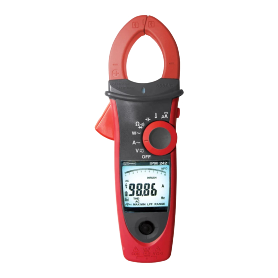
IPM 240 Series
Power Clamp Meters
EN
Table of
Contents
Previous
Page
Next
Page
1
2
3
4
5
Advertisement
Table of Contents
Need help?
Do you have a question about the IPM 241 and is the answer not in the manual?
Ask a question
Questions and answers
Related Manuals for RS PRO IPM 241
Measuring Instruments RS Pro IPM 3600N Instruction Manual
3 phase power analyser (40 pages)
Measuring Instruments RS Pro IPM 242 Instruction Manual
Ipm 240 series, power clamp meters (35 pages)
Measuring Instruments RS Pro IPM 245 Instruction Manual
Ipm 240 series, power clamp meters (35 pages)
Measuring Instruments RS PRO ICM 134 Instruction Manual
Clamp meter (19 pages)
Measuring Instruments RS Pro ICM A5 Instruction Manual
Clamp (18 pages)
Measuring Instruments RS PRO ICM A6N Instruction Manual
Clamp (18 pages)
Measuring Instruments RS Pro IM-191 Instruction Manual
Magnetic field meter (8 pages)
Measuring Instruments RS Pro ICM 20 Instruction Manual
Clamp meter (60 pages)
Measuring Instruments RS PRO IM-740 Instruction Manual
Air velocity meter (43 pages)
Measuring Instruments RS PRO IM-502 Instruction Manual
Desktop indoor air quality (iaq) monitor (70 pages)
Measuring Instruments RS PRO ISM 410 Instruction Manual
Datalogging solar power meter (22 pages)
Measuring Instruments RS PRO ISA-730 Instruction Manual
Spectrum analyzer (132 pages)
Measuring Instruments RS PRO ILOM-508A Instruction Manual
Milliohm meter (41 pages)
Measuring Instruments RS PRO ILM 1332A Instruction Manual
Digital illuminance meter (9 pages)
Measuring Instruments RS PRO ISM 400 Instruction Manual
Solar power meter (20 pages)
Measuring Instruments RS PRO ILM 1335 User Manual
(18 pages)
This manual is also suitable for:
Ipm 242
Ipm 245
Ipm 243
Ipm 244
Table of Contents
Print
Rename the bookmark
Delete bookmark?
Delete from my manuals?
Login
Sign In
OR
Sign in with Facebook
Sign in with Google
Upload manual
Upload from disk
Upload from URL


Need help?
Do you have a question about the IPM 241 and is the answer not in the manual?
Questions and answers