
Subscribe to Our Youtube Channel
Related Manuals for RS PRO IPM 3600N


Summary of Contents for RS PRO IPM 3600N
- Page 1 INSTRUCTION MANUAL IPM 3600N 3 Phase Power Analyser U12 Y-M U23 D-h U31 m-s MAG.
-
Page 3: Table Of Contents
3 Phase Power Analyser / EN CONTENTS Title Page SAFETY INFORMATION ................1 INTRODUCTION..................3 III. SPECIFICATIONS ..................4 3-1 Environmental Conditions ................. 4 3-2 Safety Specifications ................. 4 3-3 General Specifications................5 3-4 Electrical Specification................5 PARTS & CONTROLS ................9 4-1 Description of Parts &... -
Page 4: Safety Information
3 Phase Power Analyser / EN I. SAFETY INFORMATION The following symbols may appear on the instrument and in this instruction manual: Caution refer to this manual before using the instrument. This mark indicates explanation, which is particularly important that the user should read before using the instrument. - Page 5 3 Phase Power Analyser / EN WARNING • Do not hold the test leads or probes beyond the finger guards or tactile barriers • Remove all probes, test leads and accessories that are not required for the test • Always use proper terminals, switch position, and range for measurements •...
-
Page 6: Introduction
3 Phase Power Analyser / EN II. INTRODUCTION The IPM 3600N is a 3 phase power analyser for portable measurement within public mains supplies. The analyzer can be used to analyse and trouble shoot power quality issues, improve power efficiency, manage energy costs, analyze harmonics, optimize power system performance, improve power quality and analyze system data to design optimal upgrades. -
Page 7: Specifications
(non-condensing). • Storage temperature and humidity : -10 to 60°C R.H. < 70% non-condensing. 3-2 Safety Specifications IPM 3600N Power Analyser Category Rating : CAT III 1000V per IEC 61010-1 Pollution Degree 2 : IEC 61010-1 2nd Edition ICA 3600N AC current probes: Current Clamps, model ICA 3600N, to be used only with the Three-Phase power analyzer, model IPM 3600N. -
Page 8: General Specifications
3 Phase Power Analyser / EN 3-3 General Specifications • Maximum voltage between voltage input terminals and earth ground : 1000 Vrms • Maximum rated working voltage for current input : 0.35 Vrms • Maximum current for current probe : 1000 Arms •... - Page 9 3 Phase Power Analyser / EN AC Current Trms Measurement (Arms) : Accuracy Current probe Overload Nominal power Range Resolution (including current probe) output protection system frequency ±0.5%rdg±15dgts 10 to 299.9A 0.1A 0.35mV/A 1000Arms 50Hz ±1.2%rdg±15dgts 300 to 999.9A • Display item : RMS current value for each channel. Active Power measurement P (KW) : Range Resolution...
- Page 10 3 Phase Power Analyser / EN Phase angle measurement ( φ ) : Range Resolution Calculated Accuracy ±15dgt 0.1° to +180° , 0.1° to -180° 0.1° • Measurement method : Calculated from power factor COSφ, φ = COS • Display item : Phase angle of each channel and its sum of multiple channels. •...
- Page 11 3 Phase Power Analyser / EN Reactive Power Energy measurement (kVARh) : Reactive power Range Resolution Timer interval Timer Accuracy accuracy 0.001 to 9.999kVARh 0.001kVARh ±1.0%rdg±20dgts 0.01 to 99.99kVARh 0.01kVARh (10 to 299.9A) 1 sec ±50ppm (25°C, 77°F) 0.1 to 999.9kVARh 0.1kVARh ±1.5%rdg±20dgts 0.001 to 9.999MVARh 0.001MVARh...
-
Page 12: Parts & Controls
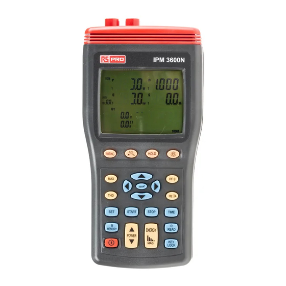
3 Phase Power Analyser / EN IV. PARTS & CONTROLS 4-1 Description of Parts & Control keys Ⅲ U12 Y-M U23 D-h U31 m-s MAG. Figure 2. Description of Parts & Control keys 09/30/16 Version No. 00... - Page 13 3 Phase Power Analyser / EN 1. Input for voltage terminals (U1, U2, U3, N). Note the 3 inputs are not galvanically isolated, they have the common reference point “N” (neutral). 2. Input sockets for current probes (I1, I2, I3, I4). 3.
- Page 14 3 Phase Power Analyser / EN Maximum reading for Reactive power (“Q” mark is blinking) with its P, S, V, A reading and its PF, Θ, Hz, I4 reading by press “PFΘ” and “Hz I4” keys. Maximum reading for Apparent power (“S” mark is blinking) with its P, Q, V, A reading and its PF, Θ, Hz, I4 reading by press “PFΘ”...
- Page 15 3 Phase Power Analyser / EN 18. STOP key : Stop auto data logging function. Press “START” key to resume recording in current data sets. 19. MEMORY key : Manual data memory control key. Press “MEMORY” key each time to store one set of current display reading into the memory, the “M”...
-
Page 16: Description Of Display
3 Phase Power Analyser / EN 4-2 Description of Display The multi-line display shows the currently measured primary values. The display format, symbols and the units (V, kV, A, kA, W, kW, MW etc...) are automatically displayed to match the selected values and functions and mode of operation. 4.13 4.14 4.15 4.16... - Page 17 3 Phase Power Analyser / EN : Auto power off indication. P : Harmonic active power measured display indicator. P1 : Phase 1 active power measured display indicator. P2 : Phase 2 active power measured display indicator. P3 : Phase 3 active power measured display indicator. Pt : Total active power measured display indicator and total active energy measured display indicator.
- Page 18 3 Phase Power Analyser / EN : Phase angle unit 4.16 ϕ : Phase angle display 4.17 Indicates current measurement from input “I4” A : Unit of current 4.18 Hz : Unit of frequency 4.19 4.20 KVA : Apparent power unit or KVAh, MVAh : Apparent energy unit. 4.21 Display value of apparent power 4.22...
-
Page 19: Operating Instructions
3 Phase Power Analyser / EN V. OPERATING INSTRUCTIONS DANGER • Voltage input connectors U1 to, U2 & U3 are not galvanically isolated, they have the common reference point “N” (neutral) • Only connect the necessary number of test leads and probes for the test. WARNING •... -
Page 20: Alignment Marks
3 Phase Power Analyser / EN (See Figure 1. Current Probe Positional Error and Figure 4. ICA 3600N Current Probe) 1. Connect the current probe to the instrument. 2. Connect the current probe jaws around the conductor to be measured Centre the conductor inside the current probe jaw Make sure the probe is perpendicular to the conductor Ensure the arrow on the top of the probe faces towards the load of the circuit... -
Page 21: Single-Phase 2-Wire (1P2W) Power System Measurement
3 Phase Power Analyser / EN 5-2 Single-Phase 2-Wire (1P2W) Power System Measurement L1 : Phase, N : Neutral, G : Ground, Face the current probe arrows toward the load. Ⅲ Figure 5. 1P2W Wiring Connection Diagram Note: U1 must be connected to the voltage source during the measurement of I1 because U1 is the main signal source of the whole instrument measuring system. - Page 22 3 Phase Power Analyser / EN 1. Press “ ” key to turn on the instrument. 2. Press “WIRING” key to select the 1P2W electrical system test, the “1P2W” symbol will be displayed. 3. Connect the voltage test leads and current probes to the instrument: Connect the black voltage test lead to the “N”...
-
Page 23: Single-Phase 3-Wire (1P3W) Power System Measurement
3 Phase Power Analyser / EN 5-3 Single-Phase 3-Wire (1P3W) Power System Measurement L1, L2 : Phase 1, Phase 2, N : Neutral, G : Ground Face the current probe arrows toward the load Ⅲ Figure 7. 1P3W Wiring Connection Diagram Note: U1 must be connected to the voltage source during the measurement of U2, I1 and I2, because U1 is the main signal source of the whole instrument measuring system. - Page 24 3 Phase Power Analyser / EN 1. Press key to turn on the instrument. 2. Press “WIRING” key to select the 1P3W electrical system test, the “1P3W” symbol will be displayed. 3. Connect the voltage test leads and current probes to the instrument : Connect the black voltage test lead to the “N”...
-
Page 25: Three-Phase 3-Wire (3P3W2M) Power System Measurement
3 Phase Power Analyser / EN a). KW displays KWh b). KVAR displays KVARh c). KVA displays KVAh Press “STOP” key to stop and hold the energy measurements. The “ HOLD ” symbol is displayed and the final calculation time appears in the “STOP” line on the display. Press “↵... - Page 26 3 Phase Power Analyser / EN Figure 10. 3P3W2M General Display 1. Press key to turn on the instrument. 2. Press “WIRING” key to select the 3P3W2M electrical system test, the “3P3W2M” symbol will be displayed. 3. Connect the voltage test leads and current probes to the instrument : Connect the black voltage test lead to the “N”...
- Page 27 3 Phase Power Analyser / EN 5. Press “ POWER ” key to select between Phase 1(P1, Q1, S1, PF1), Phase 2 (P2, Q2, S2, PF2) and total (Pt, Qt, St, PFt) measured values. 6. Frequency (Hz), Phase Angle (Θ) and Power Factor (pF) measurement: Press “PFΘ”...
-
Page 28: Three-Phase 3-Wire (3P3W3M) Power System Measurement
3 Phase Power Analyser / EN 5-5 Three-Phase 3-Wire (3P3W3M) Power System Measurement Using 3 power meter method L1, L2, L3 : Phase 1, Phase 2, Phase 3, G : Ground, Face the current probe arrows toward the load Ⅲ Figure 11. - Page 29 3 Phase Power Analyser / EN 1. Press key to turn on the instrument. 2. Press “WIRING” key to select the 3P3W3M electrical system test, the “3P3W3M” symbol will be displayed. 3. Connect the voltage test leads and current probes to the instrument : Connect the red voltage test lead to the “U1”...
-
Page 30: Three-Phase 4-Wire (3P4W) Power System Measurement
3 Phase Power Analyser / EN 5-6 Three-Phase 4-Wire (3P4W) Power System Measurement L1, L2, L3 : Phase 1, Phase 2, Phase 3, N: Neutral, G : Ground, Face the current probe arrows toward the load Ⅲ Figure 13. 3P4W Wiring Connection Diagram Figure 14. - Page 31 3 Phase Power Analyser / EN 1. Press key to turn on the instrument. 2. Press “WIRING” key to select the 3P4W electrical system test, the “3P4W” symbol will be displayed. 3. Connect the voltage test leads and current probe to the instrument: Connect the black voltage test lead to the “N”...
-
Page 32: Single Phase Current Measurement
3 Phase Power Analyser / EN 10. Energy measurement: Press “ENERGY” key, the “Pt”, “Qt”, “St” and “PFt” or “φt” symbol are displayed and the starting time of the energy measurement is displayed in the “STAR” line. The energy values and the current time will be displayed during the energy measurement. -
Page 33: Manual Data Memory And Read Function Operation
3 Phase Power Analyser / EN 5-8 Manual Data Memory and Read Function Operation 1. Clear memory data : Press key to turn off the instrument. Press and hold down the “MEMORY” key then press key again to turn on the instrument, and to enter clear manual memory data mode, the “DATA M CLr 1 YES no”... -
Page 34: Phase Sequence Measurement
3 Phase Power Analyser / EN Press “STOP” key to stop recording data, press “START” key to resume recording data, but maximum can be divide to 99 memory blocks, the current block number will be displayed (01 ~ 99). When the maximum block or maximum capacity is full, the “DATA FULL” symbol will be displayed and data recording is automatically stopped. - Page 35 3 Phase Power Analyser / EN 1. Press key to turn on the instrument. 2. Press “WIRING” key to select the 3P4W electrical system test, the “3P4W” symbol will be displayed. 3. Connect the voltage test leads to the instrument: Connect the red voltage test lead to the “U1”...
-
Page 36: Voltage, Current Waveform And Harmonic Analyzer
3 Phase Power Analyser / EN 5-11 Voltage, Current Waveform and Harmonic Analyzer These measurements can be performed via a PC using the software supplied. Please refer to software manual (on the CD-ROM) for waveform and harmonic measurement. 5-12 Enable Auto Power Off Function The instrument will automatically enter sleep mode after approximately 30 minutes to save power consumption, when enable auto power function. -
Page 37: Maintenance
3 Phase Power Analyser / EN VI. MAINTENANCE 6-1 General Maintenance 1. Repairs or services that are not covered in this manual should only be performed by qualified personnel. 2. Clean the instrument and accessories with a damp cloth and a mild soap. Do not use abrasives, solvent, or alcohol. -
Page 38: Software Installation And Operation
3 Phase Power Analyser / EN VII. SOFTWARE INSTALLATION AND OPERATION For the detailed instructions, please refer to the content of the CD-ROM, which has the complete instructions for the software operation and relevant information. 09/30/16 Version No. 00... -
Page 39: Limited Warranty
Limited Warranty This meter is warranted to the original purchaser against defects in material and workmanship for 3 years from the date of purchase. During this warranty period, RS Components will, at its option, replace or repair the defective unit, subject to verification of the defect or malfunction. This warranty does not cover fuses, disposable batteries, or damage from abuse,... - Page 40 Africa RS Components SA P.O. Box 12182, Vorna Valley, 1686 20 Indianapolis Street, Kyalami Business Park, Kyalami, Midrand South Africa www.rs-components.com Asia RS Components Pte Ltd. 31 Tech Park Crescent Singapore 638040 www.rs-components.com China RS Components Ltd. Suite 23 A-C East Sea Business Centre Phase 2 No.
Need help?
Do you have a question about the IPM 3600N and is the answer not in the manual?
Questions and answers