
Subscribe to Our Youtube Channel
Related Manuals for National Instruments NI PXIe-8115


Summary of Contents for National Instruments NI PXIe-8115
- Page 1 PXI Express NI PXIe-8115 User Manual NI PXIe-8115 User Manual December 2011 373615A-01...
- Page 2 11500 North Mopac Expressway Austin, Texas 78759-3504 USA Tel: 512 683 0100 For further support information, refer to the Technical Support and Professional Services appendix. To comment on National Instruments documentation, refer to the National Instruments Web site at and enter ni.com/info the Info Code feedback ©...
- Page 3 Warranty The NI PXIe-8115 is warranted against defects in materials and workmanship for a period of one year from the date of shipment, as evidenced by receipts or other documentation. National Instruments will, at its option, repair or replace equipment that proves to be defective during the warranty period.
- Page 4 CUSTOMIZED AND DIFFERS FROM NATIONAL INSTRUMENTS' TESTING PLATFORMS AND BECAUSE A USER OR APPLICATION DESIGNER MAY USE NATIONAL INSTRUMENTS PRODUCTS IN COMBINATION WITH OTHER PRODUCTS IN A MANNER NOT EVALUATED OR CONTEMPLATED BY NATIONAL INSTRUMENTS, THE USER OR APPLICATION DESIGNER IS ULTIMATELY...
- Page 5 Furthermore, any changes or modifications to the product not expressly approved by National Instruments could void your authority to operate it under your local regulatory rules.
-
Page 6: Table Of Contents
Introduction Benefits of PXI Express....................1-1 NI PXIe-8115.........................1-2 Description ......................1-2 Functional Overview ..................1-2 NI PXIe-8115 Functional Description ..........1-2 National Instruments Software ..................1-4 Chapter 2 Installation and Configuration Installing the NI PXIe-8115...................2-1 How to Remove the Controller from the PXI Express Chassis.......2-4 BIOS Setup Utility......................2-4... - Page 7 Front Panel........................3-2 DisplayPort...................... 3-3 COM1......................3-5 Ethernet ......................3-6 Parallel Port..................... 3-7 Universal Serial Bus..................3-9 Trigger......................3-10 GPIB (IEEE 488.2) ..................3-11 ExpressCard/34 Slot..................3-13 Front Panel Features ...................... 3-15 Data Storage ........................3-15 NI PXIe-8115 User Manual viii ni.com...
- Page 8 General Questions......................4-1 Boot Options ........................4-2 Cables and Connections....................4-3 Software Driver Installation...................4-4 Upgrade Information......................4-5 PXI Express Configuration ....................4-6 Chapter 5 Troubleshooting Appendix A Specifications Appendix B Technical Support and Professional Services Glossary Index © National Instruments Corporation NI PXIe-8115 User Manual...
-
Page 9: About This Manual
National Instruments PXIe-8115 embedded computer kit. How to Use the Documentation Set Begin by reading the NI PXIe-8115 Installation Guide, a brief quick-start guide that describes how to install and get started with your controller. This manual, the NI PXIe-8115 User Manual, contains more details about changing the installation or configuration from the defaults and using the hardware. -
Page 10: Related Documentation
PXI-5 PXI Express Hardware Specification, Revision 1.0, PXI Systems Alliance • PXI-6 PXI Express Software Specification, Revision 1.0, PXI Systems Alliance • Serialized IRQ Support for PCI Systems Specification, Revision 6.0, Compaq Computer et al. • ExpressCard Standard, Release 1.0, PCMCIA NI PXIe-8115 User Manual ni.com... -
Page 11: Introduction
Introduction This chapter provides overview information for PXI Express and the NI PXIe-8115 embedded controller. Benefits of PXI Express The PXI (PCI eXtensions for Instrumentation) industry standard, an open specification governed by the PXI Systems Alliance (PXISA), has quickly gained adoption and grown in prevalence in test, measurement, and control systems since its release in 1998. -
Page 12: Ni Pxie-8115
NI PXIe-8115 embedded computer. NI PXIe-8115 Functional Description The NI PXIe-8115 is a modular PC in a PXI Express 3U-size form factor. Figure 1-1 is a functional block diagram of the NI PXIe-8115. Following the diagram is a description of each logic block shown. - Page 13 Panel Trigger Serial Super I/O Parallel Figure 1-1. NI PXIe-8115 Block Diagram The NI PXIe-8115 consists of the following logic blocks on the CPU module and the I/O (daughter card) module. The CPU module has the following logic blocks: ® ™...
-
Page 14: National Instruments Software
The PXIe Connectors connect the NI PXIe-8115 to the PXI Express/CompactPCI Express backplane. National Instruments Software National Instruments has developed several software tools you can use with the NI PXIe-8115. National Instruments’ hardware and software work together to help you make the most of your PXI Express system. - Page 15 RTSI or PXI synchronization, self-calibration, messaging, and acquiring data to extended memory. For more information visit ni.com/daq National Instruments’ Modular Instruments use specialized drivers suited to each product’s specialization. Express VIs provide customized, interactive programming of instruments in a single interface and soft front panels provide an interface for testing the functionality of each instrument with no programming required.
- Page 16 NI-Sync. For more information visit ni.com/pxi NI-VISA is the National Instruments implementation of the VISA specification. VISA is a uniform API for communicating and controlling USB, Serial, GPIB, PXI, VXI, and various other types of instruments. This API aids in the creation of portable applications and instrument drivers.
-
Page 17: Installation And Configuration
NI PXIe-8115 controller. Installing the NI PXIe-8115 This section contains general installation instructions for the NI PXIe-8115. Consult your PXI Express chassis user manual for specific instructions and warnings. Plug in your chassis before installing the NI PXIe-8115. The power cord grounds the chassis and protects it from electrical damage while you install the module. - Page 18 1 Protective Screw Cap (4x) Figure 2-1. Removing Protective Screw Caps Make sure the injector/ejector handle is in its downward position. Align the NI PXIe-8115 with the card guides on the top and bottom of the system controller slot. Caution Do not raise the injector/ejector handle as you insert the NI PXIe-8115.
- Page 19 What if the NI PXIe-8115 does not boot? section of Chapter 5, Troubleshooting. Figure 2-2 shows an NI PXIe-8115 installed in the system controller slot of a National Instruments NI PXIe-1082 chassis. 1 NI PXIe-1082 Chassis 3 Injector/Ejector Rail 2 NI PXIe-8115 Controller Figure 2-2.
-
Page 20: How To Remove The Controller From The Pxi Express Chassis
If the PXI Express chassis Inhibit Mode Selector Switch is not in the Default position, any attempt to shut down the NI PXIe-8115 through the push button reset or using Windows will result in the controller Power OK LED blinking. The user will be required to use the Remote Inhibit pin on the Remote Inhibit and Voltage Monitoring Connector to turn off the chassis. -
Page 21: Main Setup Menu
The Main setup menu reports the following configuration information: • BIOS Version and Build Date—These values indicate the version of the NI PXIe-8115 controller BIOS and the date on which the BIOS was built. • Embedded Firmware Version—This value helps identify the built-in hardware capabilities. -
Page 22: Advanced Setup Menu
Power/Wake Configuration—Use this setting to access the Power/Wake Configuration submenu. Refer to the Power/Wake Configuration Submenu section for more information. • ExpressCard Configuration—Use this setting to access the ExpressCard Configuration submenu. Refer to the ExpressCard Configuration Submenu section for more information. NI PXIe-8115 User Manual ni.com... -
Page 23: Sata Configuration Submenu
Hyper-Threading increases performance for some applications by adding virtual CPU cores. Hyper-Threading can increase application jitter, so care should be taken when enabling this setting on a Real Time system. When the BIOS is configured to boot LabVIEW © National Instruments Corporation NI PXIe-8115 User Manual... -
Page 24: Video Configuration Submenu
Primary Display—This setting specifies which video adapter the BIOS should use as the primary adapter if more than one is present. To use an external video adapter as the primary graphics adapter, choose Add-in Board Video. The default value is Onboard Video. NI PXIe-8115 User Manual ni.com... -
Page 25: Power/Wake Configuration Submenu
• ExpressCard Resources—This setting enables or disables the setting of the Reserved Buses, Reserved Memory, and Reserved I/O © National Instruments Corporation NI PXIe-8115 User Manual... -
Page 26: Usb Configuration Submenu
Power-On Self Test will wait for a USB mass storage device to start. The default is 20 seconds. • Device Power-up Delay—This setting specifies the maximum time a device will take before it properly reports itself to the host controller. NI PXIe-8115 User Manual 2-10 ni.com... -
Page 27: Serial/Parallel Port Configuration Submenu
(IRQ) information for the onboard serial port. • Change Settings—This setting changes the base address and interrupt request level (IRQ) information for the onboard serial port. The default value is Auto. © National Instruments Corporation 2-11 NI PXIe-8115 User Manual... -
Page 28: Parallel Port Configuration Submenu
By default, the target will automatically attempt to connect to the network using DHCP. If the target is unable to initiate a DHCP connection, the target connects to the network with a link-local IP address or 169.254.x.x NI PXIe-8115 User Manual 2-12 ni.com... -
Page 29: Current Hardware Switch Settings
You can set these to Allow Override which will let you change the actual settings that can be found in the Advanced Setup Menu. • CPU Hyper Threading—The default is Use RT Default. • CPU C-States—The default is Use RT Default. © National Instruments Corporation 2-13 NI PXIe-8115 User Manual... -
Page 30: Boot Setup Menu
Hard Drive BBS Priorities—Use this setting to access the Hard Drive BBS Priorities submenu to re-order or disable bootable hard drive devices. Refer to the Hard Drive BBS Priorities Submenu section for more information. NI PXIe-8115 User Manual 2-14 ni.com... -
Page 31: Boot Settings Configuration Submenu
CD/DVD ROM drive devices. The highest priority device is displayed on the main Boot Option Priorities list. Optionally, each device can also be Disabled if the device should never be used as a boot device. © National Instruments Corporation 2-15 NI PXIe-8115 User Manual... -
Page 32: Floppy Drive Bbs Priorities Submenu
• Save Changes and Reset—Any changes made to BIOS settings are stored in NVRAM. The setup program then exits and reboots the controller. The <F10> key can also be used to select this option. NI PXIe-8115 User Manual 2-16 ni.com... -
Page 33: Bios Diagnostic Utilities
Complete the following steps to start the BIOS Diagnostic Utility. Power on or reboot your controller. When the message <F2> to run diagnostics appears, press the <F2> key. The first diagnostic utility loads after a short delay. © National Instruments Corporation 2-17 NI PXIe-8115 User Manual... -
Page 34: Hard Drive Diagnostic Utility
Note instructed to turn off the controller and replace the memory. System CMOS The NI PXIe-8115 contains memory backed up by a battery to store BIOS configuration information. Complete the following steps to clear the CMOS contents: Power off the chassis. -
Page 35: Labview Rt Installation
PXI Express embedded controller setup to run LabVIEW Real-Time. In this section you will configure the boot mode of the controller, verify or change IP settings, and install LabVIEW Real-Time software. © National Instruments Corporation 2-19 NI PXIe-8115 User Manual... - Page 36 Click Yes to automatically reboot the RT target. You may also reboot the controller by right-clicking on the target name under Remote Systems and selecting Reboot. NI PXIe-8115 User Manual 2-20 ni.com...
-
Page 37: Labview Rt Configuration Switches
If you are not using LabVIEW RT, these switches should remain in the OFF position. The controller reads these switches only after a system reset. The NI PXIe-8115 controller includes the following LabVIEW RT configuration switches: •... - Page 38 The switches are shown in the OFF position. 1 Switch 1—Boot LabVIEW RT 3 Switch 3—Disable Startup VI 2 Switch 2—Boot Safe Mode 4 Switch 4—Reset IP Address Figure 2-4. LabVIEW RT Configuration Switches NI PXIe-8115 User Manual 2-22 ni.com...
-
Page 39: Drivers And Software
PXI Express Features PXI Express Trigger Connectivity The SMB connector on the NI PXIe-8115 front panel can connect to or from any PXI Express backplane trigger line. Contact National Instruments for more information. PXI Express Chassis Configuration... -
Page 40: Pxi Express System Configuration
( ). Device drivers pxisys.ini pxiesys.ini and other utility software read the files to pxiesys.ini pxisys.ini obtain system information. For detailed information about initialization files, refer to the PXI Express specification at www.pxisa.org NI PXIe-8115 User Manual 2-24 ni.com... -
Page 41: Upgrading Ram
Chapter 2 Installation and Configuration Upgrading RAM You can change the amount of installed RAM on the NI PXIe-8115 by upgrading the SO-DIMM. National Instruments offers the following SO-DIMM for use with the NI PXIe-8115 controller. PC3-10600 2 GB, 256 MB 64, 1.18 in. max •... -
Page 42: Hard Drive Recovery
Installing from a USB CD/DVD-ROM The NI PXIe-8115 supports the installation of Windows 7 or Windows XP from a USB CD/DVD-ROM. As an alternative to a USB CD/DVD-ROM drive, you can use an external SCSI CD-ROM with a PXI-SCSI adapter. -
Page 43: Expresscard
Slide the card out of the slot. Caution To avoid data loss and other potential issues, stop communication with your ExpressCard device before removing it from the NI PXIe-8115. In Windows, use the Safely Remove Hardware tool to safely stop the ExpressCard. © National Instruments Corporation... -
Page 44: I/O Information
I/O Information Front Panel Connectors Table 3-1 lists various peripherals and their corresponding NI PXIe-8115 external connectors, bus interfaces, and functions. Table 3-1. NI PXIe-8115 Peripherals Overview Peripheral External Connector Description Video DisplayPort Intel Extreme Graphics controller Serial COM1 16550 RS-232 serial port... -
Page 45: Front Panel
2.064 in. (52.43 mm) 1.818 in. (46.18 mm) 1.343 in. (34.11 mm) 1.285 in. (32.64 mm) 1.070 in. (27.19 mm) NI PXIe-8115 Embedded Controller .000 in. (0 mm) Figure 3-1. NI PXIe-8115 Front Panel Layout and Dimensions NI PXIe-8115 User Manual ni.com... -
Page 46: Displayport
Chapter 3 I/O Information DisplayPort Figure 3-2 shows the location and pinouts for the DisplayPort connector on the NI PXIe-8115. Table 3-2 lists and describes the DisplayPort connector signals. NI PXIe-8115 Embedded Controller Figure 3-2. DisplayPort Connector Location and Pinout Table 3-2. - Page 47 Chapter 3 I/O Information DisplayPort Table 3-2. Connector Signals (Continued) Signal Name ML_Lane3(p) ML_Lane3(n) CONFIG1 CONFIG2 AUX CH (p) AUX CH (n) Hot Plug Detect Return DP_PWR NI PXIe-8115 User Manual ni.com...
-
Page 48: Com1
To ensure EMC compliance, limit serial cable length to no more than 30 meters. Figure 3-3 shows the location and pinouts for the COM1 connector on the NI PXIe-8115. Table 3-3 lists and describes the COM1 connector signal. COM1 NI PXIe-8115 Embedded Controller Figure 3-3. -
Page 49: Ethernet
I/O Information Ethernet Figure 3-4 shows the location and pinouts for the Ethernet connector on the NI PXIe-8115. Table 3-4 lists and describes the Ethernet connector signals. The Wake On LAN feature is only supported by Ethernet Port 1. Note... -
Page 50: Parallel Port
1000 Mbit/sec data rate is selected. Parallel Port Figure 3-5 shows the location and pinouts for the IEEE 1284 (parallel) connector on the NI PXIe-8115. Table 3-6 lists and describes the IEEE 1284 connector signals. Parallel port adapter cables are available from National Instruments, part number 777169-01. - Page 51 Data Bit 5 Data Bit 6 Data Bit 7 INIT# Initialize Printer STROBE# Strobe SLCTIN# Select Input AUTOFD# Auto Line Feed +5 V 19–35 Ground Not Connected Note: The pound symbol (#) indicates an active low signal. NI PXIe-8115 User Manual ni.com...
-
Page 52: Universal Serial Bus
Universal Serial Bus Figure 3-6 shows the location and pinouts for the Universal Serial Bus (USB) connector on the NI PXIe-8115. Each controller has four USB ports on the front panel. Table 3-7 lists and describes the USB connector signals. -
Page 53: Trigger
The TRIG connector is the software-controlled trigger connection for routing PXI triggers to or from the backplane trigger bus. Figure 3-7 shows the TRIG connector location on the NI PXIe-8115. Table 3-8 lists and describes the trigger connector signals. NI PXIe-8115 Embedded Controller Figure 3-7. -
Page 54: Gpib (Ieee 488.2)
Chapter 3 I/O Information GPIB (IEEE 488.2) Figure 3-8 shows the location and pinouts for the GPIB connector on the NI PXIe-8115. Table 3-9 lists and describes the GPIB connector signals. National Instruments provides a GPIB mating connector, part number 183285-0R2. - Page 55 Chassis ground DIO5# Data Bit 5 DIO6# Data Bit 6 DIO7# Data Bit 7 DIO8# Data Bit 8 REN# Remote Enable 18–25 Logic Ground Note: The pound symbol (#) indicates an active low signal. NI PXIe-8115 User Manual 3-12 ni.com...
-
Page 56: Expresscard/34 Slot
Chapter 3 I/O Information ExpressCard/34 Slot The NI PXIe-8115 controller is equipped with an ExpressCard/34 slot on the front panel, which provides I/O expansion and options for removable storage, Ethernet, and a variety of other I/O. Figure 3-9 shows the location and pinouts for the ExpressCard/34 slot on the NI PXIe-8115. - Page 57 Reference Clock + Ground PERn0 PE Data Receive – PERp0 PE Data Receive + Ground PETn0 PE Data Transmit – PETp0 PE Data Transmit + Ground Note: The pound symbol (#) indicates an active low signal. NI PXIe-8115 User Manual 3-14 ni.com...
-
Page 58: Front Panel Features
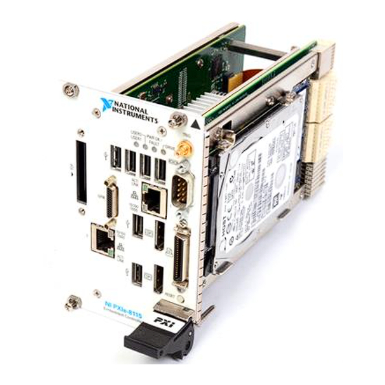
The USER2 LED is a bi-color green/yellow LED. You can define the USER2 LED to meet the needs of your LabVIEW application. Data Storage The NI PXIe-8115 has the following data storage features: • 2.5 in. SATA notebook internal hard drive •... -
Page 59: Common Configuration Questions
This chapter answers common configuration questions you may have when using a NI PXIe-8115 embedded controller. General Questions What do the LEDs on the NI PXIe-8115 front panel mean? Refer to the LED status descriptions in the Front Panel Features... -
Page 60: Boot Options
There are some limitations when booting from a USB device. Windows XP can be installed from a USB CD/DVD-ROM, but earlier versions of Windows cannot. The NI PXIe-8115 BIOS configures the USB devices so that they will work in a DOS environment. -
Page 61: Cables And Connections
How do I plug both a PS/2 mouse and PS/2 keyboard into the controller? The NI PXIe-8115 has no PS/2 connector, and you need to use a USB Y-splitter cable as shown in Figure 4-1, or a similar device, to connect both a PS/2 mouse and PS/2 keyboard. -
Page 62: Software Driver Installation
GPIB driver in the Device Manager. If you need more assistance, refer ni.com/support/install How do I install software from a CD? The compact size of the NI PXIe-8115 does not allow for an integrated USB CD/DVD-ROM drive. You have the following options: •... -
Page 63: Upgrade Information
Common Configuration Questions Upgrade Information How do I upgrade system memory? You can change the amount of installed RAM on the NI PXIe-8115 by upgrading the DDR3 SO-DIMM. To upgrade the RAM, remove the NI PXIe-8115 from the PXI chassis. -
Page 64: Pxi Express Configuration
Chapter 4 Common Configuration Questions 1 DDR3 SO-DIMM Module 2 DDR3 SO-DIMM Socket Figure 4-2. Installing a DDR3 SO-DIMM in an NI PXIe-8115 Controller How do I flash a new BIOS? You can download the new BIOS from ftp.ni.com/support/pxi For more information, refer to KnowledgeBase 2GIGKD0Z, Determining and Upgrading PXI and VXI Embedded Controller BIOS Versions. -
Page 65: Troubleshooting
This chapter answers common troubleshooting questions you may have when using the NI PXIe-8115 embedded computer. What if the NI PXIe-8115 does not boot? Several problems can cause a controller not to boot. Here are some things to look for and possible solutions. - Page 66 Press <F9> to load BIOS defaults. Answer Y (Yes) to the verification prompt. Select Save and Exit Setup. As an alternative method, complete the following steps: Power off the chassis. Remove the controller from the chassis. NI PXIe-8115 User Manual ni.com...
- Page 67 Press and hold down the pushbutton switch SW1 for 2–3 seconds. The SW1 switch location is shown in Figure 5-1. Reinstall the controller in the chassis. 1 Push-Button Switch S1 Figure 5-1. Clearing the CMOS Contents © National Instruments Corporation NI PXIe-8115 User Manual...
-
Page 68: Appendix A Specifications
Specifications This appendix lists the electrical, mechanical, and environmental specifications of the NI PXIe-8115 embedded controller. Features NI PXIe-8115 ® ™ Intel Core i5 2510E (2.50 GHz dual core processor) On-die L2 cache 3 MB Single-Channel DDR3 RAM, 2 GB Standard... - Page 69 (at 25 °C ambient temperature) Pollution Degree ........2 Indoor use only. Clean the NI PXIe-8115 with a soft nonmetallic brush. Make sure that the device Caution is completely dry and free from contaminants before returning it to service. NI PXIe-8115 User Manual...
- Page 70 Extended Temperature Option ....–40 to 71 °C (Tested in accordance with IEC-60068-2-1 and IEC-60068-2-2. Meets MIL-PRF-28800F Class 3 limits.) Relative humidity range ......5% to 95%, noncondensing (Tested in accordance with IEC-60068-2-56.) © National Instruments Corporation NI PXIe-8115 User Manual...
- Page 71 EN 61326 (IEC 61326): Class A emissions; Basic immunity • EN 55011 (CISPR 11): Group 1, Class A emissions • AS/NZS CISPR 11: Group 1, Class A emissions • FCC 47 CFR Part 15B: Class A emissions • ICES-001: Class A emissions NI PXIe-8115 User Manual ni.com...
- Page 72 To obtain product certifications and the DoC for this product, visit , search by model ni.com/certification number or product line, and click the appropriate link in the Certification column. © National Instruments Corporation NI PXIe-8115 User Manual...
- Page 73 Appendix A Specifications Environmental Management National Instruments is committed to designing and manufacturing products in an environmentally responsible manner. NI recognizes that eliminating certain hazardous substances from our products is beneficial to the environment and to NI customers. For additional environmental information, refer to the NI and the Environment Web page at .
- Page 74 Technical Support and Professional Services Visit the following sections of the award-winning National Instruments Web site at for technical support and professional services: ni.com • Support—Technical support at includes the ni.com/support following resources: – Self-Help Technical Resources—For answers and solutions,...
- Page 75 You also can visit the Worldwide Offices section of to access the branch ni.com/niglobal office Web sites, which provide up-to-date contact information, support phone numbers, email addresses, and current events. NI PXIe-8115 User Manual ni.com...
- Page 76 BIOS Basic Input/Output System—BIOS functions are the fundamental level of any PC or compatible computer. BIOS functions embody the basic operations needed for successful use of the computer’s hardware resources. © National Instruments Corporation NI PXIe-8115 User Manual...
- Page 77 Extended Capabilities Parallel. EEPROM Electronically Erasable Programmable Read Only Memory. Electromagnetic Compatibility. Electromagnetic interference. Enhanced Parallel Port. expansion ROM An onboard EEPROM that may contain device-specific initialization and system boot functionality. NI PXIe-8115 User Manual ni.com...
- Page 78 A means for a device to request service from another device. interrupt level The relative priority at which a device can interrupt. IRQ# Interrupt signal. Industry Standard Architecture—The original PC bus architecture, specifically the 16-bit AT bus. © National Instruments Corporation NI PXIe-8115 User Manual...
- Page 79 Mean time between failure. NI-488 or NI-488.2 The National Instruments software for GPIB systems. NI-DAQ The National Instruments software for data acquisition instruments. NI-VISA The National Instruments implementation of the VISA standard—An interface-independent software that provides a unified programming interface for VXI, GPIB, and serial instruments.
- Page 80 SO-DIMM Small Outline Dual In-line Memory Module. SPI Bus Serial Peripheral Interface—A standard for controlling most any digital electronics that accept a clocked serial stream of bits. © National Instruments Corporation NI PXIe-8115 User Manual...
- Page 81 Glossary Universal Serial Bus. Volts. Video Graphics Array—The minimum video display standard for all PCs. Watts. NI PXIe-8115 User Manual ni.com...
- Page 82 4-3 Configuration menu, 2-16 driver installation, 4-4 SATA Configuration menu, 2-7 general questions, 4-1 Save & Exit menu, 2-16 PXI Express configuration, 4-6 upgrade information, 4-5 configuration, PXI Express chassis, 2-23 © National Instruments Corporation NI PXIe-8115 User Manual...
- Page 83 USB, 3-1, 3-9 directory, 2-23 video, 3-1, 3-3 installation dimensions, 3-2 GPIB (IEEE 488.2), 4-4 features, 3-15 video, 4-4 LEDs, 4-1 NI resources, B-1 functional overview of NI PXIe-8115, 1-2 obtaining latest drivers, 4-6 NI PXIe-8115 User Manual ni.com...
- Page 84 2-23 LEDs, front panel LEDs, 3-15, 4-1 installation Linux support, 1-6 See also configuration LPT cable, connecting to NI PXIe-8115, 4-3 injector/ejector handle position (caution), NI PXIe-8115 installed in a PXI Express chassis (figure), 2-3 Main Setup menu, 2-5...
- Page 85 PXI Express chassis, 2-4 DDR3 SO-DIMMs from National software, 1-4 Instruments (note), 2-25, 4-5 specifications, A-1 upgrading, 2-24, 4-5 troubleshooting, 5-1 recycling upgrading RAM, 2-24, 4-5 hardware, A-6 NI support and services, B-1 related documentation, xii NI PXIe-8115 User Manual ni.com...
- Page 86 Serial/Parallel Port Configuration menu, 2-11 troubleshooting Parallel Port menu, 2-12 CMOS reset, 5-2 Serial Port menu, 2-11 controller does not boot, 5-1 setting up the NI PXIe-8115 BIOS, 2-4 damaged module, 5-2 shock and vibration specifications, A-4 NI resources, B-1 software video display, 5-2...
- Page 87 Index Y-splitter cable figure, 4-3 using mouse and keyboard without, 4-3 using with PS/2 mouse and keyboard, 2-3 NI PXIe-8115 User Manual ni.com...
Need help?
Do you have a question about the NI PXIe-8115 and is the answer not in the manual?
Questions and answers