Table of Contents
Advertisement
Quick Links
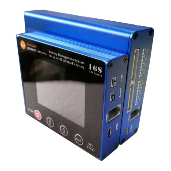
BMS16T
for 2S-16S LiPo/Li-ion, LiFe & LiTO
Low power consumption
High accuracy
2.8" TFT LCD display
Programmable
T
hanks for your purchasing the BMS16T for your vehicle.
R
ead the ENTIRE instruction manual to become familiar with the features/functions of the device
before operating. Down load the BMS installation video on
http://www.chargery.com/Video/BMS24T_C10325_operation_instructions.mp4
F
eel free to send an email to
jasonwang3a@163.com
or call at 86 755 2643 6165 should you have
any questions and suggestions.
Jason Wang
Advertisement
Table of Contents

Related Manuals for Chargery BMS16T Series


Summary of Contents for Chargery BMS16T Series
- Page 1 BMS16T for your vehicle. ead the ENTIRE instruction manual to become familiar with the features/functions of the device before operating. Down load the BMS installation video on http://www.chargery.com/Video/BMS24T_C10325_operation_instructions.mp4 eel free to send an email to jasonwang3a@163.com or call at 86 755 2643 6165 should you have any questions and suggestions.
-
Page 2: Safety Notes
LiPo & LiFe, LiTo Battery Management System BMS16T(BMS16Pro) V3.0 Chargery BMS16T is designed special for LiPo,LiFe and LiTo battery pack applied to storage energy system and Electrical Vehicle including E-Motorcycle, E-Scooter and so on. The unit can measure or detect the battery voltage, cell voltage, charge &... - Page 3 If use external adaptor, the BMS can do 2S -16S battery, and the external voltage range is 15-60V. For same Battery positive and negative terminal when charge and discharge, BMS24T can control charge and discharge separately. And detect charge and discharge current with one current shunt. www.chargery.com page 3 total 31...
-
Page 4: Order Information
CHARGERY charger, need not the charge relay, Only connect CHARGERY charger to BMS16T on COM1, when any cell reach OVP, the charge current will decrease automatically prevent any cell damaged. This feature can save charge relay cost and shorten charge time. -
Page 5: Special Features
Protection functions Cell count error protection Over charge protection Under voltage protection Over current protection when charge or discharge Over temperature protection Over differential cell voltage protection Over differential battery temperature protection Under SOC protection www.chargery.com page 5 total 31... - Page 6 Discharge Controller Cell 11+ Cell 12+ Cell 13+ Cell 14+ Temperature Sensor 1 Cell 15+ Cell 16+ Temperature Sensor 2 COM1 COM2 Current Sense COM3 BMS16T main module Beeper COM2 STOP SET/START DOWN BMS16T display module www.chargery.com page 6 total 31...
- Page 7 The COM1 port (black connector) is connected to external device such as Charger. If connect COM1 to Chargery charger, BMS16T can control charge current to shorten charge time The COM2 (gray connector) port is connected BMS main unit to display module by gray...
-
Page 8: Program Setup
DOWN change the value. Press SET/START button shortly confirm the change. After finish all setup, press SET/START for 3 seconds quit the setup menu. When quit setup mode, BMS16T will record all parameters till next change. www.chargery.com page 8 total 31... - Page 9 Balance Stop Diff Voltage Balance in Charge ON means Balance start during charge, OFF disable. Balance in Discharge ON means Balance start during discharge, OFF disable. Balance in Storage ON means Balance start during storage, OFF disable. www.chargery.com page 9 total 31...
- Page 10 BMS display each cell voltage, please enter into program setup menu to enable balance. Although balance current per cell is larger than other brand BMS, Chargery BMS16T use temperature protection prevent BMS from overheating, and has a over current protection for each cell.
- Page 11 Battery pack voltage Highest cell voltage Lowest cell voltage Difference of cell voltage Battery temperature Charge or discharge Charge or discharge current power Notes When charge or discharge current less than 1.0A, battery status will be STORAGE. www.chargery.com page 11 total 31...
- Page 12 See right picture. 11. The right interface display charge or discharge current, charged or discharged power and SoC. When SoC less than 30%, it is displayed in yellow. When under setup, the BMS will cut off discharge. www.chargery.com page 12 total 31...
-
Page 13: Specifications
Main module weight: 365g excluding accessories 10. Display module size:96×80×24 (L×W×T, mm) or 3.8×3.2×0.95 (L×W×T, inch) 11. Warning LED: 11000mCd, @ 2.0V, 20mA 12. Warning beeper: 85dB @ 12V, 25mA 13. Package: AL alloy case www.chargery.com page 13 total 31... - Page 14 BMS16T, 75mV or less shunt is suggested. BMS16T can detect charge and discharge current by same shunt. All cell voltage and current are calibrated before delivery. The 300A and 600A 75mV specification is as below. 300A shunt weight: 230g 600A shunt weight: 530g Current sensor wire www.chargery.com page 14 total 31...
-
Page 15: Current Calibration
3 seconds later, press SET/START/ save the discharge calibration. Turn off motor, Press SET/START for 3 seconds quit Program Setup, current calibration is finished. www.chargery.com page 15 total 31... - Page 16 NOTE: BMS main unit and LCD display module must be updated separately Execute Chargery update tool software, When the port number (such as com5) appears, this shows the update tool identified the BMS. Click OPEN button lock the port please.
-
Page 17: Typical Connection
For over 8S battery pack, connect 8S to socket 1 and other cells connect to socket 2 separately. Take 12S battery sample as following: Socket 1 Cell 1 Cell 2 Cell 3 Cell 4 Cell 5 Cell 6 Cell 7 Cell 8 Cell 9 Cell 10 Cell 11 Cell 12 Socket 2 STOP www.chargery.com page 17 total 31... - Page 18 16 cells connected in series Cell positive CELL 1 SOCKET 1 CELL 2 CELL 3 CELL 4 CELL 5 CELL 6 CELL 7 CHARGERY CELL 8 BMS16T CELL 9 SOCKET 2 CELL 10 CELL 11 CELL 12 CELL 13 CELL 14...
- Page 19 CELL 2 SOCKET 1 CELL 3 CELL 4 First 4S battery positive Second 4S battery negative CELL 5 CELL 6 CELL 7 CHARGERY CELL 8 BMS16T Second 4S battery positive 6S battery negative SOCKET 2 CELL 9 CELL 10 CELL 11...
- Page 20 Before connect the relay to charge or discharge controller, please confirm the coil of relay voltage. The BMS16T controller will output 12V to power the coil, and total current for charge and discharge relay don’t be larger than 2.5A. www.chargery.com page 20 total 31...
- Page 21 Before connect the relay to charge or discharge controller, please confirm the coil of relay voltage. The BMS16T controller will output 12V to power the coil, and total current for charge and discharge relay don’t be larger than 2.5A. www.chargery.com page 21 total 31...
- Page 22 Laod + Charge Discharge Coil Coil controller controller 3. For solid state relay, the driven voltage (+VDC, -VDC), adequate Heats Sink and rated load current is very important, please pay attention to its wire connection. www.chargery.com page 22 total 31...
-
Page 23: Standard Accessory
BMS16T(BMS16Pro) V3.0 Standard Accessory USB data cable Battery connection XHR-9PIN, 600mm Temperature sensor, 600mm Relay controller wire 600mm Warning LED, 300mm Warning Beeper, 300mm Current sensor wire, 600mm Communication wire COM3 Data line (4.5 meters) www.chargery.com page 23 total 31... -
Page 24: Optional Accessories
Operating Ambient Temperature -40 to +85 °C -40 to +85 °C -40 to +85 °C -40 to +85 °C -40 to +85 °C Weight, Nominal 0.3 Kg 0.5 Kg 1.0 Kg 1.6 Kg 3 Kg www.chargery.com page 24 total 31... - Page 25 Relay delay time board When battery start to discharge and power the motor, the surge current is very large, in order to restrain the current, CHARGERY designed the special board, it can fit with CHARGERY BMS8T, BMS16, BMS16T and BMS24T and so on.
- Page 26 The battery will discharge normally. When the battery is not in use, please power off the switcher to save battery energy. The switcher should be installed on convenient place to be operated. www.chargery.com page 26 total 31...
-
Page 27: Related Parts
300A charge/discharge BMS8T For 2S-8S, 1.2A balance current per cell 600A max. charge/discharge BMS24T For 2S-24S, 1.2A balance current per cell 600A max. charge/discharge C10325 AC charger for 4S-24S battery pack 1-25A charge, 1500W max. www.chargery.com page 27 total 31... - Page 28 The BMS on above picture is BMS24T, it is as a sample, the connection is as same as BMS8T and BMS16T NOTE Chargery charger decrease charge current according to “Over Charge Protection(P) Voltage” on BMS setup, so please setup the charge terminal voltage setup in accordance with Over Charge Protection(P) Voltage on BMS.
-
Page 29: Frequent Questions
When current displayed is zero, that is to say, the battery don’t be charged or discharged, press STOP button make the BMS enter into sleep mode to save battery energy.At other situations, the STOP button is disable. b) If stop charge or discharge, please operate on charger or motor. www.chargery.com page 29 total 31... -
Page 30: Version History
LiPo & LiFe, LiTo Battery Management System BMS16T(BMS16Pro) V3.0 Version History Software Version Description V3.0 Released first time www.chargery.com page 30 total 31... -
Page 31: Warranty And Service
Warranty and Service Chargery Power Co., Ltd. as manufacture of power system warrants its BMS16T and current Sensor to be free of defects in material and workmanship. This warranty is effective for 12 months from date of purchase. If within the warranty period the customer is not satisfied with the products performance resulting from a manufacturing defect, the accessory will be replaced or repaired.
Need help?
Do you have a question about the BMS16T Series and is the answer not in the manual?
Questions and answers