Table of Contents
Advertisement
Quick Links
BMS8T
for 2S-8S LiPo/Li-ion, LiFe & LiTO
Low power consumption
High accuracy
2.8‖ TFT LCD display
Programmable
Chargery BMS8T
Battery Management System for 2S-8S LiPo/Li-ion, LiFe & LiTO
Low power consumption, High accuracy, 2.8‖ TFT LCD display, Programmable
Owners Manual
V 4.1
Main Unit Software Version 4.0
LCD Unit Software Version 4.01
Revised : 6/4/2020
Advertisement
Table of Contents

Related Manuals for Chargery BMS8T Series


Summary of Contents for Chargery BMS8T Series
- Page 1 2S-8S LiPo/Li-ion, LiFe & LiTO Low power consumption High accuracy 2.8‖ TFT LCD display Programmable Chargery BMS8T Battery Management System for 2S-8S LiPo/Li-ion, LiFe & LiTO Low power consumption, High accuracy, 2.8‖ TFT LCD display, Programmable Owners Manual V 4.1 Main Unit Software Version 4.0...
- Page 2 & operational tips. Overview: The Chargery BMS8T is designed especially for LiPo, LiFe and LiTo battery packs applied to Energy Storage Systems and Electrical Vehicles including E-Motorcycle, E-Scooter and so on. The unit can measure or detect the battery voltage, cell voltage, charge & discharge current, battery temperature, and battery SOC (State of Charge), with the information displayed on the TFT color LCD screen.
-
Page 3: Table Of Contents
Charge and discharge relay lectotype for BMS8T ..................31 Chargery DC Contactor Specifications ....................... 32 Cold pressing copper tube terminal Specifications ................34 Chargery DC Contactor (DCC) configuration in Common and Separate Port ......35 Current Calibration (Shunt) ........................... 36 Firmware Upgrades via USB Port......................... 38 Update BMS main unit ............................. - Page 4 Supplemental: Single Relay with 2 channel Opti-Coupler ................. 57 Supplemental:Equipment Voltage Calibration ....................58 Supplemental: Reference Documents & Video links ..................60 Supplemental: BMS power consumption ......................61 Frequent questions ..............................62 Warranty and Service ............................... 64 www.chargery.com page 4 total 64...
-
Page 5: Safety Notes
Copyright@Chargery Power Co., Ltd. All rights reserved. Without prior written consent by Shenzhen Chargery Power Co., Ltd, any units or individual extract and copy parts or entire contents of this manual, and transmission in any form is illegal and strictly prohibited. -
Page 6: Specifications
Under voltage protection Over current protection when charge or discharge High temperature protection Low temperature protection (on LCD unit V3.03) Over differential cell voltage protection in discharge Over differential battery temperature protection Under SOC protection www.chargery.com page 6 total 64... -
Page 7: Version History
Optimize over charge protection, don’t cut off charge when cell voltage V1.19 difference over setup. V1.20 optimize current detection V1.21 add current mode send out V1.22 Add SOC send out Add cell internal resistance measurement V4.0 Add cell internal resistance send tout Optimize SOC calculation www.chargery.com page 7 total 64... -
Page 8: Update / Change Log
13. If using external adapter, the BMS can support 2S-8S battery, the external voltage range is 15-30V. 14. The BMS uses one Current Shunt to detect Charge & Discharge current per battery pack. The BMS controls Charge & Discharge relays separately www.chargery.com page 8 total 64... -
Page 9: Order Information
Warning Beeper, 300mm monitor battery temperature. Current sensor wire, 600mm, Communication wire (4.5 COM3 Data line: connect to monitor charge /discharge meters), connect main unit to external device, send out all current LCD unit data www.chargery.com page 9 total 64... -
Page 10: Current Shunt
All supplied shunts are voltage and current calibrated prior to delivery. If you exchange the shunt, 75mV or less is recommended, and need calibrate again. www.chargery.com page 10 total 64... -
Page 11: Optional Accessories
The Relay Delay Time board is to avoid a surge current when start to charge or discharge. If using a CHARGERY DCC, the delay board is not required, because it has a Built-in the surge suppressing circuit. For other SSR or mechanical relay, please consider the surge current seriously and make a suitable plan. -
Page 12: Cold Pressing Copper Tube Terminal
LiPo & LiFe, LiTo Battery Management System BMS8T V4.1 Cold pressing copper tube terminal When you order the DCC, the tube terminal will be delivered with DCC. DCC model DCC-100HB DCC-200HB DCC-300HB DCC-600HB Terminal model 10-6 25-6 50-8 50-8 www.chargery.com page 12 total 64... -
Page 13: Operational Description
The BMS8T can be used with any lithium battery charger, when any cell is over charged, the BMS8T will open the charge relay to cut off charge, if used with a CHARGERY charger, the charge control is handled by connecting the CHARGERY charger to the BMS8T on COM1, when any cell reach OVP, the charge current will decrease automatically to prevent any cell damage. -
Page 14: Special Features
Sleep Mode to save energy consumption, Charge / Discharge are disabled and the LCD back light is turned off. Press any key to resume normal work mode. 18. LCD back light ON time can be programmed to save energy, when it is OFF, press any key to activate. www.chargery.com page 14 total 64... -
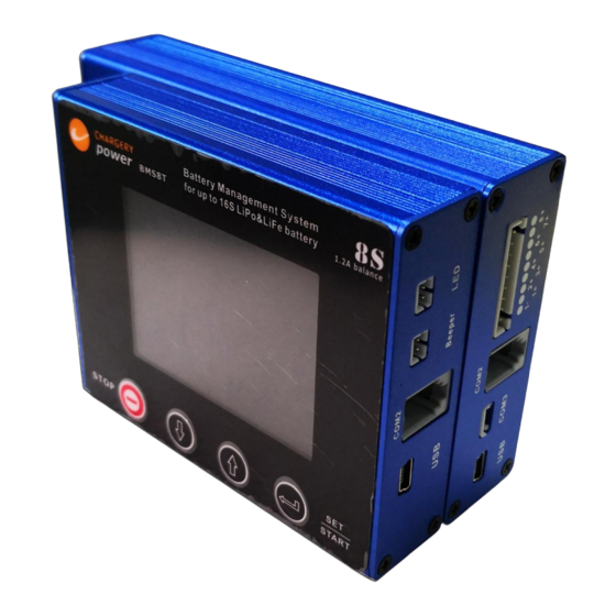
Page 15: Interface
LiPo & LiFe, LiTo Battery Management System BMS8T V4.1 Interface BMS8T Main Module BMS8T Display Module www.chargery.com page 15 total 64... - Page 16 The COM1 port (black connector) is connected to external device such as Charger. If COM1 connected to Chargery charger, BMS8T can control charge current to shorten charge time The COM2 (gray connector) port is connected BMS Main Unit to Display Module with the...
-
Page 17: Hardware Setup
LiFe 2.00V will force discharge to cut off LiTO 1.50V LiPo ℃ Over / Under temperature, BMS8T will cutoff the LiFe 80℃ Battery temperature charge and discharge LiTO Next Step is to configure the Software. www.chargery.com page 17 total 64... -
Page 18: Software Configuration
UP or DOWN to change the value. Press SET/START button quickly to confirm the change. After finishing all of the setup, press SET/START for 3 seconds to save & quit the setup menu. When you quit setup mode, BMS8T will save all the parameters till next change. www.chargery.com page 18 total 64... -
Page 19: Parameters Setting
Balance Stop Diff Voltage Balance in Charge ON means Balance start during charge, OFF disable. Balance in Discharge ON means Balance start during discharge, OFF disable. Balance in Storage ON means Balance start during storage, OFF disable. www.chargery.com page 19 total 64... - Page 20 One Li-on (NMC) cell, rated voltage is 3.6V, if capacity is 10AH, battery power is 36WH One LiPO cell, rate voltage is 3.7V, if capacity is 10AH, battery power is 37WH One LiFe cell, rate voltage is 3.25V, if capacity is 10AH, battery power is 32.5WH www.chargery.com page 20 total 64...
- Page 21 If wh calculate based on other voltage, the WH will be lower or higher, it is bad. Some battery label has WH and AH, if without WH, WH calculation based on AH battery rated voltage is suggested, Ah and rated voltage must be found in battery datasheet. www.chargery.com page 21 total 64...
-
Page 22: Operating Guideline
LiPo & LiFe, LiTo Battery Management System BMS8T V4.1 Operating guideline Installation video: http://chargery.com/Video/BMS24T_C10325_operation_instructions.mp4 INSTRUCTIONS on Navigating Menu Press SET/START button for 3 seconds enter into Program Setup interface. Press UP/DOWN button to select the item, press SET/START quickly to make the value flash, and press UP/DOWN to change the value. - Page 23 When any warning events are triggered, Press UP or DOWN, you can check which cell triggered the warning events (over charge or over discharge), the voltage will be recorded till next warning. See figure www.chargery.com page 23 total 64...
- Page 24 But the yellow bar is displayed means the cell is in balancing. See ―Balancing Indicator‖ on page 28. COM2 is to connect to charger if you have CHARGERY charger, COM3 is to connect to external device. www.chargery.com page 24 total 64...
-
Page 25: Soc Calibration
When you turn off BMS, the actual SOC, WH and AH will be saved, and displayed when you turn on BMS. This feature avoids re-calibrating SOC. As Charge and Discharge cycles increase, the battery capacity will be decreased, that is to say, the actual www.chargery.com page 25 total 64... - Page 26 ―over charge protection (P) voltage‖ to 4.0V (LiPo), and ―over discharge protection (P) voltage‖ (LiPo) to 3.3V, means the battery SOC will be used from 10% to 90%. This will extended the battery pack life-cycle and make the system safer in general. www.chargery.com page 26 total 64...
-
Page 27: Balancer
After the BMS display is connected and configured with the cell voltages, reenter into program setup menu to enable balance. Although the balancing current per cell is larger than some other brand BMS', the Chargery BMS8T uses temperature protection prevent the BMS from overheating and has over current protection for each cell. -
Page 28: Balancing Indicator
Example below. Balancing in Discharge, cell 5 and cell 12 are Balancing in Charge, cell 1,6,10,11 and in balancing. cell 16 are in balancing. Balancing in Storage, except cell 11, other cells are in balancing. www.chargery.com page 28 total 64... -
Page 29: Cell Internal Resistance (Impedance) Test
―good‖ or ―bad‖ cell. Ideally, each cell in series should have same internal resistance, if the difference of cell internal resistance is very large, the higher resistance cell must be ―bad‖, and caused large cell voltage difference, then shorten the total battery life. www.chargery.com page 29 total 64... - Page 30 You can record the cell internal resistance, and compare new cell internal resistance with the cell used for several months, then you can find which cell has the highest internal resistance. www.chargery.com page 30 total 64...
-
Page 31: Charge And Discharge Relay Lectotype For Bms8T
SSR can be installed on the battery positive or negative, if is not isolated, the SSR must be installed on the battery negative. Chargery DCC (DC contactor) can be fit with Chargery BMS, it is designed special for the BMS. www.chargery.com... -
Page 32: Chargery Dc Contactor Specifications
BMS8T V4.1 Chargery DC Contactor Specifications Chargery DC Contactor is designed special fit with Chargery BMS. One DCC can be used in common port, and get both charge & discharge signal, When any cell is over charged, or over discharged or DCC over temperature, the DCC will be open and stop charging or discharging. - Page 33 LiPo & LiFe, LiTo Battery Management System BMS8T V4.1 Chargery DCC installation details. Warning: when install Lugs, both lugs don’t be short circuit or touch the DCC case at the same time. DCC MODEL L/mm W/mm T/mm D/mm Bolt Size...
-
Page 34: Cold Pressing Copper Tube Terminal Specifications
DCC-600HB Terminal /Lug Model 10-6 25-6 50-8 D±0.2 mm d±0.2 mm G±0.3 mm L±1.5 mm L1±1 mm W±1 mm ¢±0.5 mm AWG1/0 = 0 AWG2/0 = 00 Cable AWG AWG5 (16.8mm AWG2 (33.6mm (53.5mm (67.5mm www.chargery.com page 34 total 64... -
Page 35: Chargery Dc Contactor (Dcc) Configuration In Common And Separate Port
Compare with SSR (Solid State Relay), the Chargery DCC is bi-directional and can handle up to 600A current at 100V DC. ONE Chargery bi-directional DCC can be used in common port, and receive both HV and LV cut off signal. If not using the Chargery DCC, you would require two SSR's or two relays, which would increase power consumption and have a higher cost. -
Page 36: Current Calibration (Shunt)
BMS8T V4.1 Current Calibration (Shunt) Current calibration is only required if you change the Shunt from the one supplied by Chargery which are calibrated at the factory. Use shunts which are 75mv or lower only. Press SET/START for 3 seconds to enter into Program Setup and find the Current Calibration, you can calibrate the current to improve the measurement accuracy. - Page 37 Current calibration is not suggested. We calibrate shunt and current before delivery. You only need to re- calibrate if you change shunts from the ones supplied by Chargery. If the current is not accurate, the WH and AH will not be accurate. SOC reading will also be wrong.
-
Page 38: Firmware Upgrades Via Usb Port
Generally the USB driver is not needed for the BMS8T, 16T and 24T. If it is needed, please install USB driver on PC from the Chargery downloads. Main unit V4.0 cannot communicate with a lower version LCD, such as V3.03, it means, when press START button on LCD unit, the BMS WON’T start. -
Page 39: Update Bms Main Unit
The file should be .hex file. Such as BMS16T_V4.00_APP.hex, it is for BMS16T LCD model. Click Update button start to update, the update progress bar will be on PC and LCD, update complete information will be displayed on PC. www.chargery.com page 39 total 64... - Page 40 After BMS main unit and LCD unit updated to V4.0, please enter into program setup interface and press UP or DOWN choose Default Settings, then choose Enable press START button, resume all parameters settings as default. As below. Resume default settings in factory BMS16T-300 Main unit firmware version www.chargery.com page 40 total 64...
-
Page 41: Typical Cell Connections
2S-3S battery connected to the socket 1 directly, but an external power supply is required. 8S configuration allows for battery / external to power the BMS. The BMS requires 15-30 VDC @ 3A. 2S-4S configuration and 8S configuration www.chargery.com page 41 total 64... -
Page 42: 4S & 4S With Single Bms8T Configuration Example
LiPo & LiFe, LiTo Battery Management System BMS8T V4.1 4s & 4s with single BMS8T configuration example. www.chargery.com page 42 total 64... -
Page 43: 6P4S 24 Cells With Single Bms8T Configuration Example
LiPo & LiFe, LiTo Battery Management System BMS8T V4.1 6P4S 24 cells with single BMS8T configuration example. Nissan Leaf battery 6P8S with BMS8T configuration example www.chargery.com page 43 total 64... -
Page 44: Separate Port Configuration Example-With Chargery Dcc
BMS8T V4.1 Separate Port Configuration example—with Chargery DCC Chargery DCC can connect to BMS8T directly, do not need install delay time board or others. The Charge DCC should be 1.25 times the maximum amperage provided by the charging devices. The Discharge Relay should be 1.25 times the maximum amperage draw expected. -
Page 45: Separate Port Configuration Example-With Mechanical Relay
NOTE ! Fuses, DC Breakers are not shown. Please use Best Practices and install appropriate fuses and breakers according to local codes and other guidelines. ATTENTION ! The relay on above Configuration is bi-directional or uni-directional SSR/mechanical relay. But SSR must be isolated. www.chargery.com page 45 total 64... -
Page 46: Common Port Configuration Example-With Chargery Dcc
LiPo & LiFe, LiTo Battery Management System BMS8T V4.1 Common Port Configuration example—with Chargery DCC On this configuration, both Charge & Discharge cut off is realized by one Charger DC contactor, and do not need install relay delay time board. 100A – 600A 100V bi-directional DCC is available, only 11mA power consumption from battery when it is turned on. -
Page 47: Common Port Configuration Example-With Mechanical Relay
Fuses, DC Breakers are not shown. Please use Best Practices and install appropriate fuses and breakers according to local codes and other guidelines. The relay on above Configuration is bi-directional or uni-directional SSR/mechanical relay. But must be isolated. www.chargery.com page 47 total 64... -
Page 48: 4P4S Cell Configuration With Bms8T-600 Example
LiPo & LiFe, LiTo Battery Management System BMS8T V4.1 4p4s Cell configuration with BMS8T-600 example ATTENTION ! Fuses and Breakers should be installed according to your specific application and usage. Failure to do so may result in Damage or Injury. www.chargery.com page 48 total 64... -
Page 49: 4S Packs With 3 In Parallel Connection Using 3 Bms8T's Example
Failure to do so may result in Damage or Injury. If not use Chargery DCC on above Configuration, need 2 SSR or Mechanical relay for each battery, total is 6pcs SSR or relay. www.chargery.com page 49 total 64... -
Page 50: Relay Delay Time Board (Optional Accessory)
When a Motor and many Inverters are started, the initial surge is very large. In order to restrict the current surge, CHARGERY designed this special delay board, it can work with CHARGERY BMS8T, BMS16, BMS16T and BMS24T and so on. - Page 51 Please close all other switcher's on other devices, finally turn on the switcher on the board and the battery will start to charge or discharge. 12V: The resistor value should be over 0.24 OHM 24V: The resistor value should be over 0.24 OHM 48V: The resistor value should be over 0.48 OHM ---- www.chargery.com page 51 total 64...
-
Page 52: Relay Delay Board Implementation Examples
BMS8T V4.1 Relay Delay Board Implementation Examples: If using a CHARGERY DCC, the delay board is not needed (connection diagram is on page 46). The Small Relay in this example is a simple automotive "Make & Break relay". The simplest and most common form of relay. -
Page 53: Relay Delay Board Implementation Examples Con't
LiPo & LiFe, LiTo Battery Management System BMS8T V4.1 Relay Delay Board Implementation Examples con't. If use CHARGERY DCC, do not need install the board (connection diagram is on page 44). ATTENTION ! The charge relay on above Configuration is bi-directional or uni-directional SSR/mechanical relay. -
Page 54: Related Parts
600A max. charge/discharge BMS24T For 2S-24S, 1.2A balance current per cell 600A max. charge/discharge C3060 AC charger for 1S-8S battery pack 1-60A charge, 1500W max. C10325 AC charger for 4S-24S battery pack 1-25A charge, 1500W max. www.chargery.com page 54 total 64... -
Page 55: Total Solution On E-Vehicle Application-1500W 60A 8S Battery Charger
Total solution on E-Vehicle application—1500W 60A 8S battery charger If using the Chargery charger, the charge relay can be ignored, BMS8T can communicate with charger, when any cell is over charged, BMS will send a signal to charger, the charger will decrease charge current till the cell voltage within safe values. -
Page 56: Supplemental: Solid State Relay Supplemental Information
If it is not isolated, please install it on battery negative, connect between Load inverter/charger negative and current shunt. If use CHARGERY DCC, one DCC is enough for the Common Port application (connection diagram is on page 46). -
Page 57: Supplemental: Single Relay With 2 Channel Opti-Coupler
(-) from the battery but from the converter only. Thanks to user "Onemorebattery" from Diysolarforum.com. Chargery DCC solved the problem, one DCC uses in a Common Port configuration, and does not need the relay board. Detailed connection is on page 46. -
Page 58: Supplemental:equipment Voltage Calibration
Inverter/Charger sees, so that it cuts off exactly at the voltage desired "at the battery terminal end". So IF you want the LVD to kick on when the cells reach 2.75VDC ea / 22.0 VDC for the www.chargery.com page 58 total 64... - Page 59 Inverter/Charger to manage on an ongoing basis. Continually using the BMS to do this function can actually affect the BMS negatively and may even result in damage, it is not what they are designed to do. www.chargery.com page 59 total 64...
-
Page 60: Supplemental: Reference Documents & Video Links
Current calibration: How to calibrate Chargery BMS Shunt (BMS24T, BMS24T, BMS24T) BMS current calibration by power supply https://www.youtube.com/watch?v=bCM_cau0TD0 Chargery BMS update firmware on Main & LCD modules to v4.0 https://www.youtube.com/watch?v=4nrYUm1uhAs Chargery BMS. Package and settings walk-trough. https://www.youtube.com/watch?v=7ggsGRL8VC0 Configure 16s LiFePo4 to 48V battery---Connecting balancing leads to battery and Capacity test. -
Page 61: Supplemental: Bms Power Consumption
100A 200A 300A 600A BMS drain current from battery (mA) 96.25 25.5 74.75 21.75 17.5 Chargery DC Contactor power consumption at 12V driven voltage when it is closed. DCC-100HB DCC-200HB DCC-300HB DCC-600HB 11mA 11mA 11mA www.chargery.com page 61 total 64... -
Page 62: Frequent Questions
When current displayed is ZERO, that is to say, the battery is not charging or discharging, press STOP button to make the BMS enter into sleep mode to save battery energy. If you need wake up the BMS, please press UP, DOWN or START Button. www.chargery.com page 62 total 64... - Page 63 Show timeout during updating, Download the correct firmware according to product model and save to your PC, from http://chargery.com/update.asp Update tool software version must be v1.03 or greater. Always use the most current. Connect BMS main unit or LCD unit to the PC by using the provided USB cable.
-
Page 64: Warranty And Service
BMS8T V4.1 Warranty and Service Chargery Power Co., Ltd. as manufacture of power system warrants its BMS16T and current Sensor to be free of defects in material and workmanship. This warranty is effective for 12 months from date of purchase. If within the warranty period the customer is not satisfied with the products performance resulting from a manufacturing defect, the accessory will be replaced or repaired.
Need help?
Do you have a question about the BMS8T Series and is the answer not in the manual?
Questions and answers