Table of Contents
Advertisement
Quick Links
BMS24T
for 2S-24S LiPo, LiFe & LiTO
Low power consumption
High accuracy
2.8" TFT LCD display
Programmable
Thanks for your purchasing the BMS24T for your vehicle.
Please read the ENTIRE instruction manual to become familiar with the
features/functions of the BMS24T before operating or connecting any power sources
(battery or external) to the BMS24T. It is suggested that you view the BMS installation
video
from
http://www.chargery.com/Video/BMS24T_C10325_operation_instructions.mp4
or
https://www.youtube.com/watch?v=39lYl3h1kOU
with Nissan Leaf battery
Feel free to send an email to
jasonwang3a@163.com
or call at (86) 755-2643 6165
should you have any questions and suggestions.
Jason Wang
Thanks to Steve_S from
https://diysolarforum.com
, he rewrite the manual and make it easy
to understand
Revised : 3/15/2020
Advertisement
Table of Contents

Related Manuals for Chargery BMS24T Series


Summary of Contents for Chargery BMS24T Series
- Page 1 BMS24T before operating or connecting any power sources (battery or external) to the BMS24T. It is suggested that you view the BMS installation video from http://www.chargery.com/Video/BMS24T_C10325_operation_instructions.mp4 https://www.youtube.com/watch?v=39lYl3h1kOU with Nissan Leaf battery Feel free to send an email to jasonwang3a@163.com...
-
Page 2: Safety Notes
Copyright@Chargery Power Co., Ltd. All rights reserved. Without prior written consent by Shenzhen Chargery Power Co., Ltd, any units or individual extract and copy parts or entire contents of this manual, and transmission in any form is illegal and strictly prohibited. -
Page 3: Updated Features
Added RS232 port, allowing for external devices to read out the data from the BMS. Additional Information on the data is located here: http://chargery.com/uploadFiles/bms24_additional_protocol%20V1.22.pdf For same Battery positive and negative terminal when charge and discharge, BMS24T can control charge and discharge separately. -
Page 4: Order Information
The BMS24T can be used with any lithium battery charger, when any cell is over charged, the BMS24T will open the charge relay to cut off charge, if used with a CHARGERY charger, the charge control is handled by connecting the CHARGERY charger to the BMS24T on COM1, when any cell reach OVP, the charge current will decrease automatically to prevent any cell damage. -
Page 5: Special Features
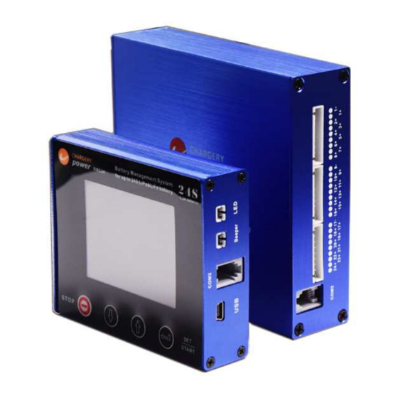
Under voltage protection Over current protection when charge or discharge High temperature protection Low temperature protection (on LCD unit V3.03) Over differential cell voltage protection in discharge Over differential battery temperature protection Under SOC protection www.chargery.com page 5 total 41... - Page 6 LiPo & LiFe, LiTo Battery Management System BMS24T V4.0 Interface BMS24T Main Module BMS24T Display Module www.chargery.com page 6 total 41...
- Page 7 The COM1 port (black connector) is connected to external device such as Charger. If COM1 connect to Chargery charger, BMS24T can control charge current to shorten charge time The COM2 (gray connector) port is connected BMS main unit to display module by gray...
-
Page 8: Program Setup
DOWN change the value. Press SET/START button shortly confirm the change. After finish all setup, press SET/START for 3 seconds quit the setup menu. When quit setup mode, BMS24T will record all parameters till next change. www.chargery.com page 8 total 41... - Page 9 Balance Stop Diff Voltage Balance in Charge ON means Balance start during charge, OFF disable. Balance in Discharge ON means Balance start during discharge, OFF disable. Balance in Storage ON means Balance start during storage, OFF disable. www.chargery.com page 9 total 41...
- Page 10 Balance current is 1.2A max. per cell, 9. Setup accurate battery capacity, then charge or discharge 25% of the battery capacity, the BMS will calibrate SOC automatically, 10. Main Unit software version www.chargery.com page 10 total 41...
- Page 11 Although the balancing current per cell is larger than some other brand BMS', the Chargery BMS24T uses temperature protection prevent the BMS from overheating and has over current protection for each cell.
- Page 12 BMS24T V4.0 Operating guideline Installation video: https://www.youtube.com/watch?v=39lYl3h1kOU http://chargery.com/Video/BMS24T_C10325_operation_instructions.mp4 Connect Beeper, LED, to the Display Module. Connect the shunt, current sensor wire, relays, relay controller wires and Temperature Sensors to BMS24T Main Module. Connect battery wires to BMS24T, ensure correct cell polarity.
- Page 13 25% at least, the SOC can be calibrated automatically. • COM2 is to connect to charger if you have CHARGERY charger, COM3 is to connect to external device. www.chargery.com page 13 total 41...
-
Page 14: Specifications
Main module weight: 420g excluding accessories Display module size:96×80×24 (L×W×T, mm) or 3.8×3.2×0.95 (L×W×T, inch) Display module weight: 130g excluding accessories Warning LED: 11000mCd, 2.0V, 20mA Warning beeper: 85dB 12V, 25mA Package: AL alloy case www.chargery.com page 14 total 41... - Page 15 All supplied shunts are voltage and current calibrated prior to delivery. The 300A and 600A 75mV specification is as below. 300A shunt weight: 230g 600A shunt weight: 530g Current sensor wire www.chargery.com page 15 total 41...
-
Page 16: Current Calibration
3 seconds later, press SET/START/ save the discharge calibration value. Turn off the load, Press SET/START for 3 seconds quit Program Setup and current calibration is finished. Youtube video: How to calibrate Chargery BMS Shunt (BMS8T, BMS16T, BMS24T) Thanks Jimmy in USA. www.chargery.com... - Page 17 NOTE: BMS Main Unit and LCD Display Module must be updated separately Execute Chargery update tool software, When the port number (such as com5) appears, this shows the update tool identified the BMS. Click OPEN button lock the port please.
-
Page 18: Typical Connections
2S-15S battery connected to the socket 1 and socket 2 directly, but external power supply is required. For 15S or less configuration allows for external to power the BMS. The BMS requires 13-100 VDC 6S battery connection to the socket 1 directly, external power supply is required. Example below. www.chargery.com page 18 total 41... - Page 19 LiPo & LiFe, LiTo Battery Management System BMS24T V4.0 Typical Connection continued, For 8S / 12S battery pack, connect 8S to socket 1, then socket 2 separately. See 12S example below: www.chargery.com page 19 total 41...
- Page 20 LiPo & LiFe, LiTo Battery Management System BMS24T V4.0 Typical Connection continued, Typical 24S connection using all 3 sockets. www.chargery.com page 20 total 41...
- Page 21 LiPo & LiFe, LiTo Battery Management System BMS24T V4.0 Typical Connection continued, www.chargery.com page 21 total 41...
- Page 22 Example: (2000W ÷ 12V = 166A X 1.25 = 208A) (2000W ÷ 24V = 83.3A X 1.25 = 105A) NOTE ! Fuses, DC Breakers are not shown. Please use Best Practices and install appropriate fuses and breakers according to local codes and other guidelines. www.chargery.com page 22 total 41...
- Page 23 Example: (2000W ÷ 12V = 166A X 1.25 = 208A) (2000W ÷ 24V = 83.3A X 1.25 = 105A) NOTE ! Fuses, DC Breakers are not shown. Please use Best Practices and install appropriate fuses and breakers according to local codes and other guidelines. www.chargery.com page 23 total 41...
- Page 24 For Solid State Relays, the driven voltage (+VDC, -VDC), installing adequate Heats Sinks for the rated load current is very important, please pay close attention to the wiring connections. Special Note: Some SSR's (Solid State Relays) are Uni-directional, others are Bi-directional, be aware of these differences plan and purchase accordingly. www.chargery.com page 24 total 41...
- Page 25 Amperage that could pass through it, it will fail and possibly result in damage. www.chargery.com page 25 total 41...
- Page 26 When a Motor and many Inverters are started, the initial surge is very large. In order to restrict the current surge, CHARGERY designed this special delay board, it can work with CHARGERY BMS8T, BMS16, BMS16T and BMS24T and so on.
- Page 27 Please close all other switcher's on other devices, finally turn on the switcher on the board and the battery will start to charge or discharge. 12V: The resistor value should be over 0.24 OHM 24V: The resistor value should be over 0.24 OHM 48V: The resistor value should be over 0.48 OHM ---- www.chargery.com page 27 total 41...
- Page 28 For example: 24V/4000W Inverter will draw (4000W ÷ 24VDC = 166.66A) X 1.25 = 208.3A Note a Low Frequency Inverter is capable of 3X the wattage (12,000W) for momentary surge. The relays in this case should be sized 200A or greater www.chargery.com page 28 total 41...
- Page 29 For example a Solar Charge Controller at 75A, and an AC Charger at 50A equals a max input potential of 125A x 1.25 = 156A, so a relay of 150A an up would be suitable. www.chargery.com page 29 total 41...
- Page 30 LiPo & LiFe, LiTo Battery Management System BMS24T V4.0 Example Configurations Example Configurations www.chargery.com page 30 total 41...
-
Page 31: Standard Accessory
BMS24T V4.0 Standard Accessory USB data cable Battery connection XHR-9PIN, 600mm Temperature sensor, 600mm Relay controller wire 600mm Warning LED, 300mm Warning Beeper, 300mm Current sensor wire, 600mm Communication wire (3 COM3 Data line meters) www.chargery.com page 31 total 41... -
Page 32: Optional Accessories
-40 to Operating Ambient Temperature -40 to +85 °C -40 to +85 °C -40 to +85 °C -40 to +85 °C +85 °C Weight, Nominal 0.3 Kg 0.5 Kg 1.0 Kg 1.6 Kg 3 Kg www.chargery.com page 32 total 41... -
Page 33: Related Parts
COMMENTS BMS16 For 2S-16S, balance is not available. BMS8T For 2S-8S, 1.2A balance current per cell BMS16T For 2S-16S, 1.2A balance current per cell C10325 AC charger for 4S-24S battery pack 1-25A charge, 1500W max. www.chargery.com page 33 total 41... - Page 34 Total solution on E-Vehicle application If using the Chargery charger, the charge relay can be ignored, BMS24T can communicate with charger, when any cell is over charged, BMS will send a signal to charger, the charger will decrease charge current till the cell voltage within safe values.
-
Page 35: Version History
Software Version of main unit Description V1.18 first released optimize over charge protection, don’t cut off charge when cell voltage V1.19 difference over setup. V1.20 optimize current detection V1.21 add current mode send out V1.22 Add SOC send out www.chargery.com page 35 total 41... -
Page 36: Frequent Questions
When current displayed is ZERO, that is to say, the battery is not charging or discharging, press STOP button to make the BMS enter into sleep mode to save battery energy. If you need wake up the BMS, please press UP, DOWN or START Button. www.chargery.com page 36 total 41... - Page 37 222.5 266.25 38.5 26.25 BMS Relay controller output current at 12V when Chargery Mechanical Relay closed. 12V 100A relay, coil current is 0.75A at 12V drive voltage. 12V 200A relay, coil current is 0.96A at 12V drive voltage. 12V 400A relay, coil current is 1.24A at 12V drive voltage.
- Page 38 Cell voltage difference is over “Difference(Diff) of cell voltage” setting. Battery temperature is over “high temperature cutoff” setting. Battery temperature is under “low temp cutoff in discharge” setting. Battery temperature difference is over “diff of battery temp” setting. Others www.chargery.com page 38 total 41...
- Page 39 22.40. This way when the Inverter/Charger sees 22.40 Volts it cuts off as the actual batteries are at 22.0VDC. 21.60 VDC = 2.70v per cell.(uncorrected) * REMEMBER, that below www.chargery.com page 39 total 41...
- Page 40 Inverter/Charger to manage on an ongoing basis. Continually using the BMS to do this function can actually affect the BMS negatively and may even result in damage, it is not what they are designed to do. www.chargery.com page 40 total 41...
-
Page 41: Warranty And Service
BMS24T V4.0 Warranty and Service Chargery Power Co., Ltd. as manufacture of power system warrants its BMS24T and current Sensor to be free of defects in material and workmanship. This warranty is effective for 12 months from date of purchase. If within the warranty period the customer is not satisfied with the products performance resulting from a manufacturing defect, the accessory will be replaced or repaired.
Need help?
Do you have a question about the BMS24T Series and is the answer not in the manual?
Questions and answers