Table of Contents
Advertisement
Quick Links
BMS8P
for 2S-8S LiPo/Li-ion, LiFe & LiTO
Low power consumption
High accuracy
2.8" TFT LCD display
Programmable
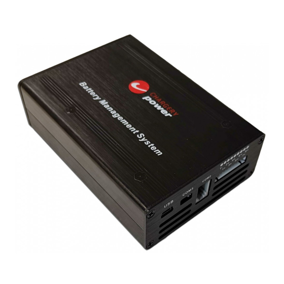
Chargery BMS8P
Battery Management System for 2S-8S LiPo/Li-ion, LiFe & LiTO
Low power consumption, High accuracy, 2.8" TFT LCD display, Programmable
Owners Manual
V 4.3
Main Unit Software Version 4.05
LCD Unit Software Version 4.03
Revised : 28/2/2020
Advertisement
Table of Contents

Related Manuals for Chargery BMS8P


Summary of Contents for Chargery BMS8P
- Page 1 2S-8S LiPo/Li-ion, LiFe & LiTO Low power consumption High accuracy 2.8” TFT LCD display Programmable Chargery BMS8P Battery Management System for 2S-8S LiPo/Li-ion, LiFe & LiTO Low power consumption, High accuracy, 2.8” TFT LCD display, Programmable Owners Manual V 4.3 Main Unit Software Version 4.05...
- Page 2 & operational tips. Overview: The Chargery BMS8P is designed especially for LiPo, LiFe and LiTo battery packs applied to Energy Storage Systems and Electrical Vehicles including E-Motorcycle, E-Scooter and so on. The unit can measure or detect the battery voltage, cell voltage, charge & discharge current, battery temperature, and battery SOC (State of Charge), with the information displayed on the TFT color LCD screen.
-
Page 3: Table Of Contents
Nissan Leaf battery 6P8S with BMS8P configuration example ............45 Separate Port Configuration example—with Mechanical relay or DCC..........46 Common Port Configuration example—with two Mechanical relay or one CHARGERY DCC..47 4p4s Cell configuration with BMS8P-600 example ..................48 Related parts ................................ - Page 4 LiPo & LiFe, LiTo Battery Management System BMS8P V4.3 Supplemental:Equipment Voltage Calibration ....................53 Supplemental: Reference Documents & Video links ..................55 Supplemental: BMS power consumption ......................56 Frequent questions ..............................57 Improve cell voltage accuracy ..........................59 Improve current reading fluctuation from Steve ................... 60 Over Current protection resume operation .....................
-
Page 5: Safety Notes
Copyright@Chargery Power Co., Ltd. All rights reserved. Without prior written consent by Shenzhen Chargery Power Co., Ltd, any units or individual extract and copy parts or entire contents of this manual, and transmission in any form is illegal and strictly prohibited. -
Page 6: Specifications
LiPo & LiFe, LiTo Battery Management System BMS8P V4.3 Specifications Battery range: 2S-8S LiPo & LiFe, LTO battery pack Accurate scope of the cell voltage: -5mV/+5mV Cell Voltage display range: 0.10~4.99V The voltage of external power:15-60V, 3A. Balance current:1.2A per cell continuously Temperature display range:-20℃~150℃,... -
Page 7: Version History
LiPo & LiFe, LiTo Battery Management System BMS8P V4.3 Version History Software Version of LCD Description unit V4.03 Released first time Software Version of Description main unit first released V4.05 Hardware Description Black mental case with cooling fan www.chargery.com page 7 total 62... -
Page 8: Update / Change Log
BMS8P v4.05 has the following changes that is compared with BMS8T, Add intelligent cooling fan, start automatically and speed is controlled by internal temperature, so BMS8T cannot update to BMS8P only by update software. And the BMS can balance cell voltage continuously, to save balance time by speed up balancing even at 1.2A per cell. -
Page 9: Order Information
LiPo & LiFe, LiTo Battery Management System BMS8P V4.3 Order information Model Description Accessories BMS8P-100 100A charge and discharge 100A shunt, and standard accessories BMS8P-300 300A charge and discharge 300A shunt, and standard accessories BMS8P-600 600A charge and discharge 600A shunt, and standard accessories... -
Page 10: Current Shunt
BMS8P V4.3 Current Shunt A single shunt is used for the BMS8P, it is delivered with BMS and other standard accessories. The BMS8P detects the charge and discharge currents using the same shunt. All supplied shunts are voltage and current calibrated prior to delivery. -
Page 11: Dc Contactor
DC Contactor CHARGERY designed the special DC contactor or named as SSR to fit with all BMS, DCC is used for cut off charge or discharge when any cell voltage reach settings to prevent any cell from damage and possibly fire. -
Page 12: Dcc Main Specification
LiPo & LiFe, LiTo Battery Management System BMS8P V4.3 DCC main Specification DC Contactor (DCC) model DCC-100HB DCC-200HB DCC-300HB DCC-600HB Driving voltage Holding current (Avg.) at 12V 11mA 11mA 11mA Rated Operating Voltage 100V Continuous (Carry) Current, Typical 100A 200A... -
Page 13: Iso Board
LiPo & LiFe, LiTo Battery Management System BMS8P V4.3 ISO board The board is designed special for DCC, as we know the DCC install on the positive side is better and safer than install on negative, so we designed the board. -
Page 14: Chargery Dc Contactor (Dcc) Configuration In Common And Separate Port
LiPo & LiFe, LiTo Battery Management System BMS8P V4.3 Chargery DC Contactor (DCC) configuration in Common and Separate Port DCC on Common port connection ISO board Chargery DCC BMS relay controller Battery fuse Charger/ Battery Pack shunt Inverter Battery (-) - Page 15 LiPo & LiFe, LiTo Battery Management System BMS8P V4.3 DCC on Separate and common port connection Inverter as load and charger, Solar panel charge battery too Inverter/charger Solar Charger Chargery DCC (Common port) Chargery DCC (Separate Port) Discharge Charge control signal...
-
Page 16: Alternator Saver
LiPo & LiFe, LiTo Battery Management System BMS8P V4.3 Alternator Saver The alternator on a car or boat needs 12V or 24V in order to magnetise the field on the alternator. Without that it will produce no current at all. Regulating this current is used in the internal regulation on an alternator to regulate the output of the alternator. - Page 17 LiPo & LiFe, LiTo Battery Management System BMS8P V4.3 Common port DCC connection diagram with 2 8S batteries. www.chargery.com page 17 total 62...
- Page 18 LiPo & LiFe, LiTo Battery Management System BMS8P V4.3 Separate port DCC connection diagram with 2 8S batteries. www.chargery.com page 18 total 62...
-
Page 19: Operational Description
The BMS8P includes a Main Unit and a Display Module. Once the hardware installation is completed and ready, power on the BMS8P to finish setting up all of the parameters using the Display Module. The BMS8P will use the saved settings even if the Display Module is disconnected from the Main Unit. Removing the Display Module disables the data display, beeper and warning LED but the BMS will still function properly and can cut off charge / discharge when any set condition requires it. -
Page 20: Special Features
14. Supports upgrading the firmware program by USB port. 15. BMS8P provide users the maximum flexibility, key parameters can be programmed. 16. BMS8P displays battery SOC as a dial gauge. Cell count, battery pack voltage and battery gauge (%) temperature is displayed simultaneously. -
Page 21: Interface
LiPo & LiFe, LiTo Battery Management System BMS8P V4.3 Interface BMS8P Main Module BMS8P Display Module www.chargery.com page 21 total 62... - Page 22 COM2 gray coil wire COM3 Output RS232 level with the port, any external device can read out all data from BMS8P Two temperature sensors monitor the battery temperature, the sensor must be attached Temperature to the battery surface or gap between cells where the temperature should be the highest sensor during charge or discharge.
-
Page 23: Hardware Setup
Turn on BMS by moving the Power Selector to turn on the device. BMS8P will initialize the beeper and LED, beeper will sound one time, then displays BMS8P and version, the battery type and cell count interface is displayed. Three battery types LiPo, LiFe and LTO can be selected. -
Page 24: Software Configuration
UP or DOWN to change the value. Press SET/START button quickly to confirm the change. After finishing all of the setup, press SET/START for 3 seconds to save & quit the setup menu. When you quit setup mode, BMS8P will save all the parameters till next change. www.chargery.com... -
Page 25: Parameters Setting
LiPo & LiFe, LiTo Battery Management System BMS8P V4.3 Parameters Setting----Configuration Values NOTE: Please keep the default setup values unless your application requires special settings. Parameters Min. Type Max. Step unit Charge Protection LiPo 3.90 4.20 4.35 0.01 LiFe 3.40 3.65... - Page 26 Always on means the LCD back-light will be ON forever. NO means BMS8P will not cut off charge or discharge but alarm by LED flash and Beeper Sound. Cut-Off Delay Time is very important and different for different battery capacities and applications, please carefully verify and use proper settings for your application.
- Page 27 LiPo & LiFe, LiTo Battery Management System BMS8P V4.3 One LiTO cell, rated voltage is 2.3V,if capacity is 10AH, battery power is 23WH LiFe Example: If four LiFe cell are connected in series, the rated battery voltage will be 13V with the cells at 3.25V, If each cell capacity is 280AH, the total battery power is 3640WH @ 3.25V per cell.
-
Page 28: Operating Guideline
Cell count range is 2S to 8S, the cell count will be identified automatically when the battery pack connect to the BMS8P. Press DOWN / UP button to choose the item and press SET/START until the selection blinks, then press DOWN / UP button to modify, finally press SET/START button to run the BMS8P or wait for 8 seconds start automatically. - Page 29 RED text. The difference of cell voltage and the difference of battery temperature is also displayed. When any warning events are triggered, the BMS8P will go to the interface and display error information. Such as if the battery connection has broken down and the cell count is wrong an ERROR will be displayed in turn.
- Page 30 But the yellow bar is displayed means the cell is in balancing. See “Balancing Indicator” on page 28. • COM2 is to connect to charger if you have CHARGERY charger, COM3 is to connect to external device. www.chargery.com page 30 total 62...
-
Page 31: Soc Calibration
LiPo & LiFe, LiTo Battery Management System BMS8P V4.3 SOC Calibration The program calculates SOC according to the power charged or discharged from battery. Users need to setup battery power (WH) and battery capacity (AH) when turning on the BMS for the first time. After charging to Maximum voltage or discharge to minimum voltage, BMS will complete the SOC calibration and display accurate SOC. - Page 32 LiPo & LiFe, LiTo Battery Management System BMS8P V4.3 battery capacity will reduce over time. You may find that the SOC is not 100% when the battery is fully charged (each cell voltage reaches maximum value), such as 90%. This means battery WH or AH is only 90% of the original setting.
-
Page 33: Balancer
BMS8P V4.3 Balancer The BMS8P can restore balanced cell voltage status in the shortest time, it is based on a 1.2A balancing current per cell, with balancing accuracy of 8mV. Balancing can be operated in Storage, Charge, Discharge or in ALL modes, the feature can be configured in the program setup menu. The balance function is disabled by default. -
Page 34: Balancing Indicator
LiPo & LiFe, LiTo Battery Management System BMS8P V4.3 Balancing Indicator From firmware v4.0, the BMS has a yellow indicator, when the BMS is balancing cell voltage in Storage, Charging or Discharging. The "yellow bar" will be displayed after cell voltage reading, when cell are not in balancing mode, the yellow bar will be not displayed. -
Page 35: Cell Internal Resistance (Impedance) Test
LiTo Battery Management System iFe, LiTo Battery Management System BMS8 BMS8 BMS8P V4.3 Cell internal resistance (Impedance) test resistance (Impedance) test Internal resistance of an energy storage device, Internal resistance of an energy storage device, such as a battery, is an importance parameter that is an importance parameter that determines their power performance. - Page 36 LiPo & LiFe, LiTo Battery Management System BMS8P V4.3 EXAMPLE: One 16S LiPo battery pack is in discharging at 3A, BMS measured all cell internal resistance. The total battery resistance is 19.2mohm, and the difference of each cell resistance is 1.7mohm.
-
Page 37: Charge And Discharge Relay Lectotype For Bms8P
Charge and discharge relay lectotype for BMS8P The BMS8P can output 12V/3A to power the charge and discharge DCC/relay/SSR that is used for cut off charge or discharge when any cell voltage reach settings. The relay coil drive voltage must be 12V and the total current for charge and discharge relays cannot exceed 2.5A. -
Page 38: Current Calibration (Shunt)
BMS8P V4.3 Current Calibration (Shunt) Current calibration is only required if you change the Shunt from the one supplied by Chargery which are calibrated at the factory. Use shunts which are 75mv or lower only. Press SET/START for 3 seconds to enter into Program Setup and find the Current Calibration, you can calibrate the current to improve the measurement accuracy. - Page 39 Current calibration is not suggested. We calibrate shunt and current before delivery. You only need to re- calibrate if you change shunts from the ones supplied by Chargery. If the current is not accurate, the WH and AH will not be accurate. SOC reading will also be wrong.
-
Page 40: Firmware Upgrades Via Usb Port
If loading the wrong firmware, the BMS may be damaged and won’t resume operations. Generally the USB driver is not needed for the BMS8P, 16T and 24T. If it is needed, please install USB driver on PC from the Chargery downloads. -
Page 41: Update Bms Main Unit
LiPo & LiFe, LiTo Battery Management System BMS8P V4.3 show it, please check the USB data cable and BMS turned on or not. After running USB driver, when right image showed, please press INSTALL button, continue to install the driver. - Page 42 LiPo & LiFe, LiTo Battery Management System BMS8P V4.3 Finish update, the BMS will start automatically. You can find the main unit version on the bottom line of program setup interface, when power on BMS, you can find the LCD module version on the first interface.
-
Page 43: Typical Cell Connections
LiPo & LiFe, LiTo Battery Management System BMS8P V4.3 Typical Cell Connections There are 1 socket connecting to 2S-8S battery pack, There is 1 socket connecting to 2S-8S battery pack, 2S-3S battery connected to the socket 1 directly, but an external power supply is required. -
Page 44: 4S & 4S With Single Bms8P Configuration Example
LiPo & LiFe, LiTo Battery Management System BMS8P V4.3 4s & 4s with single BMS8P configuration example. www.chargery.com page 44 total 62... -
Page 45: 6P4S 24 Cells With Single Bms8P Configuration Example
LiTo Battery Management System iFe, LiTo Battery Management System BMS8 BMS8 BMS8P V4.3 6P4S 24 cells with single single BMS8P configuration example. configuration example. Nissan Leaf battery 6P8 Nissan Leaf battery 6P8S with BMS8P configuration example configuration example www.chargery.com page 45 total 62... -
Page 46: Separate Port Configuration Example-With Mechanical Relay Or Dcc
Before connecting the relay's for charge or discharge control, please confirm the coil relay voltage is correct for the voltage being used. The BMS8P controller outputs 12V to power the coil and the total current for charge and discharge relay's cannot be larger than 2.5A. In this configuration, the Charge Relay should be 1.25 times the maximum amperage provided by the charging devices. -
Page 47: Common Port Configuration Example-With Two Mechanical Relay Or One Chargery Dcc
LiPo & LiFe, LiTo Battery Management System BMS8P V4.3 Common Port Configuration example—with two Mechanical relay or one CHARGERY DCC. This configuration requires that both Charge & Discharge Relay's are capable of handling equal amperage. Example: (2000W ÷ 12V = 166A X 1.25 = 208A) (2000W ÷ 24V = 83.3A X 1.25 = 105A) ATTENTION ! Fuses, DC Breakers are not shown. -
Page 48: 4P4S Cell Configuration With Bms8P-600 Example
LiPo & LiFe, LiTo Battery Management System BMS8P V4.3 4p4s Cell configuration with BMS8P-600 example ATTENTION ! Fuses and Breakers should be installed according to your specific application and usage. Failure to do so may result in Damage or Injury. -
Page 49: Related Parts
LiPo & LiFe, LiTo Battery Management System BMS8P V4.3 Related parts The following device is related with BMS8P MODEL DESCRIPTION COMMENTS BMS16 For 2S-16S, without cell balancer 300A charge/discharge BMS16T For 2S-16S, 1.2A balance current per cell 600A max. charge/discharge BMS24T For 2S-24S, 1.2A balance current per cell... -
Page 50: Total Solution On E-Vehicle Application-1500W 60A 8S Battery Charger
The Chargery Charger and BMS can save a relay cost and shorten the charge time. The BMS on above picture is BMS24T, it is as a sample, the connection is as same as BMS8P and BMS16T NOTE Chargery charger decrease charge current according to “Over Charge Protection(P) Voltage”... -
Page 51: Supplemental: Solid State Relay Supplemental Information
If it is not isolated, please install it on battery negative, connect between Load inverter/charger negative and current shunt. If use CHARGERY DCC, one DCC is enough for the Common Port application (connection diagram is on page 14). -
Page 52: Supplemental: Single Relay With 2 Channel Opti-Coupler
(-) from the battery but from the converter only. Thanks to user "Onemorebattery" from Diysolarforum.com. Chargery DCC solved the problem, one DCC uses in a Common Port configuration, and does not need the relay board. Detailed connection is on page 46. -
Page 53: Supplemental:equipment Voltage Calibration
LiPo & LiFe, LiTo Battery Management System BMS8P V4.3 Supplemental:Equipment Voltage Calibration Various components such as Solar Charger Controllers, Inverter/Chargers need to "know" the precise voltages being dealt with in regards to the batteries, with Lithium Based batteries, accurate voltage sensing is essential. - Page 54 LiPo & LiFe, LiTo Battery Management System BMS8P V4.3 24V pack/bank, the LVD setting will have to be adjusted to 22.40. This way when the Inverter/Charger sees 22.40 Volts it cuts off as the actual batteries are at 22.0VDC. 21.60 VDC = 2.70v per cell.(uncorrected) * REMEMBER, that below 2.80V per cell the voltage drops very fast as you in the...
-
Page 55: Supplemental: Reference Documents & Video Links
Current calibration: How to calibrate Chargery BMS Shunt (BMS24T, BMS24T, BMS24T) BMS current calibration by power supply https://www.youtube.com/watch?v=bCM_cau0TD0 Chargery BMS update firmware on Main & LCD modules to v4.0 https://www.youtube.com/watch?v=4nrYUm1uhAs Chargery BMS. Package and settings walk-trough. https://www.youtube.com/watch?v=7ggsGRL8VC0 Configure 16s LiFePo4 to 48V battery---Connecting balancing leads to battery and Capacity test. -
Page 56: Supplemental: Bms Power Consumption
100A 200A 300A 600A BMS drain current from battery (mA) 96.25 25.5 74.75 21.75 17.5 Chargery DC Contactor power consumption at 12V driven voltage when it is closed. DCC-100HB DCC-200HB DCC-300HB DCC-600HB 11mA 11mA 11mA www.chargery.com page 56 total 62... -
Page 57: Frequent Questions
LiPo & LiFe, LiTo Battery Management System BMS8P V4.3 Frequent questions Charge or Discharge relay/DC contactor won’t open (disconnect) or close (connect) Confirm the relay coil driven voltage, it must be 12V. Confirm relay coil current requirement, it must not be over 1A for each relay or that the total current with two relays won't be over 2.6A... - Page 58 LiPo & LiFe, LiTo Battery Management System BMS8P V4.3 The STOP button will NOT stop an Inverter while drawing power and will NOT stop charging if there is current from the Charger. Loads & Charger must be OFF to allow the BMS to enter into Sleep Mode.
-
Page 59: Improve Cell Voltage Accuracy
The schottky current I(av) depends on relay or SSR driven current, the schottky current must be over the two mechanical relay total driven current. al relay total driven current. For Chargery DCC, 1A even 0.5A is enough. www.chargery.com... -
Page 60: Improve Current Reading Fluctuation From Steve
LiPo & LiFe, LiTo Battery Management System BMS8P V4.3 Improve current reading fluctuation from Steve Sometimes the current reading on BMS LCD fluctuate even at a large scope, the main reason is caused by EMI from charger or inverter. On BMS, there are low pass filter to limit the EMI, but it is not always effective. -
Page 61: Over Current Protection Resume Operation
LiPo & LiFe, LiTo Battery Management System BMS8P V4.3 Over Current protection resume operation When charge or discharge current is over setting, the BMS will cut off charge or discharge without any delay, the current value and HIGH will be flashed in turn. It is named as over current protection. -
Page 62: Warranty And Service
BMS8P V4.3 Warranty and Service Chargery Power Co., Ltd. as manufacture of power system warrants its BMS16T and current Sensor to be free of defects in material and workmanship. This warranty is effective for 12 months from date of purchase. If within the warranty period the customer is not satisfied with the products performance resulting from a manufacturing defect, the accessory will be replaced or repaired.
Need help?
Do you have a question about the BMS8P and is the answer not in the manual?
Questions and answers