Advertisement
Quick Links
LOVATO ELECTRIC S.P.A.
LOVATO ELECTRIC S.P.A.
24020 GORLE (BERGAMO) ITALIA
24020 GORLE (BERGAMO) ITALIA
VIA DON E. MAZZA, 12
VIA DON E. MAZZA, 12
TEL. 035 4282111
TEL. 035 4282111
TELEFAX (Nazionale): 035 4282200
TELEFAX (Nazionale): 035 4282200
TELEFAX (International): +39 035 4282400
TELEFAX (International): +39 035 4282400
L
L
E
E
E-mail info@
E-mail info@
ovato
ovato
lectric.com
lectric.com
L
L
E
E
Web
Web
www.
www.
ovato
ovato
lectric.com
lectric.com
WARNING!
– Carefully read the manual before the installation or use.
– This equipment is to be installed by qualified personnel, complying to current standards, to avoid damages or safety
hazards.
– Remove eventual dangerous voltage from the product before any maintenance operation on it.
– The manufacturer cannot be held responsible for electrical safety in case of improper use of the equipment.
– Products illustrated herein are subject to alteration and changes without prior notice. Technical data and descriptions
in the documentation are accurate, to the best of our knowledge, but no liabilities for errors, omissions or
contingencies arising therefrom are accepted.
– A circuit breaker must be included in the electrical installation of the building. It must be installed close by the
equipment and within easy reach of the operator.
It must be marked as the disconnecting device of the equipment: IEC /EN 61010-1 § 6.11.
– Fit the instrument in an enclosure or cabinet with minimum IP51 degree protection.
– Clean the instrument with a soft dry cloth, do not use abrasives, liquid detergents or solvents.
INTRODUCTION
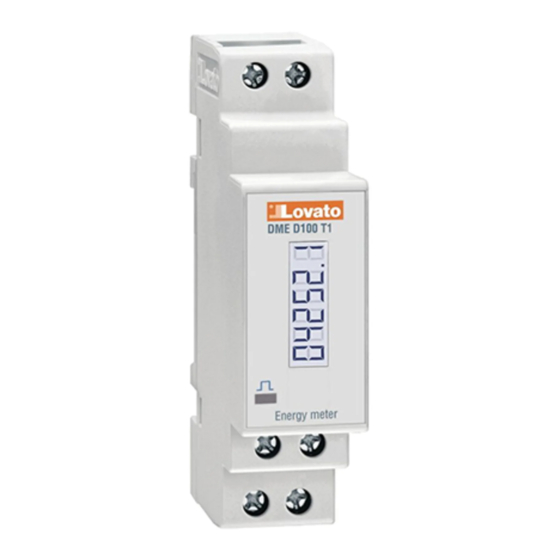
The DME D110 T1 is a single-phase active and reactive energy meter for direct connection, for currents up to 40A.
The energy accuracy is compliant with reference standard EN50470-3.
Apart from energy metering, it can measure additional indications, for a total of 10 measurements that can be viewed on
the LCD display.
The DME D110 T1 has a standard 1U (18mm wide) modular housing and is supplied with sealable terminal blocks.
DESCRIPTION
– Modular DIN-rail housing, 1U (18mm wide)
– Direct connection for currents up to 40A
– Active energy measure complies IEC/EN 62053-21 Class 1
– LCD display with 5+1 digits
– Key for measure selection and programming
– Total active and reactive energy meters
– Partial active and reactive energy meters, resettable
– Hour counter, total and partial
– Pulse LED for active energy consumption
– Indication of instantaneous consumption (active power)
– Programmable static output, for pulse or alarm threshold.
SELECTION OF READINGS
– Pressing briefly the
key, it is possible to select the readings on the display, following the sequence in the table
reported below.
– Each measurement is indicated by the corresponding icon in the upper part of the display.
– After one minute has elapsed after the last keystroke, the display moves automatically back to the total active energy
screen.
Icon
Measurement
kWh
Total active energy
kWh + Part ‚
Partial active energy
kvarh
Total reactive energy
kvarh + Part ‚
Partial reactive energy
V
Voltage
A
Current
kW
Active power
kvar
Reactive power
PF
Power factor
Fr
Frequency
h ƒ
Hour counter (hhhhh.mm)
h + Part ‚ƒ
Partial hour counter (hhhhh.mm)
kW +d „
Average active power (15 min demand)
kW+ Hd „
Max avg. active power (max demand)
‚ The measurement is shown alternatively to wording PART
ƒ These measurements are shown only enabling parameter P-08
„ These measurements are shown only enabling parameter P-09
METROLOGICAL LED
– The red LED on the front emits 1000 pulses for every kWh of consumed Energy (that is, one pulse every Wh).
– The pulsing rate of the LED gives an immediate indication of the energy flowing in every moment.
– The pulse duration, LED colour and intensity are compliant with the reference standards that define its utilisation in
order to verify the accuracy of the energy meter.
PROGRAMMABLE INSULATED STATIC OUTPUT
– The static output on the upper terminals can be used either as a pulse output or as a measurement threshold output.
– The connection can be done in PNP or NPN mode. See schematic diagrams and technical characteristics for details on
the wiring and on the rating.
– When the output is programmed as a pulse generator, it allows connecting the energy meter to:
• An external data concentrator (like DME CD)
• A remote electromechanical counter
• A PLC or other device.
– When it works as an alarm threshold, it can be used for:
• Disconnection of non-priority loads
• Alarm signalling.
NOTE: During parameter setting (setup), the status of the static output is not updated.
INCORRECT WIRING INDICATION
– In case of incorrect wiring, when the device detects a reverse energy flow, the display shows the blinking code ErrOR 3.
– This error is caused by either reverse connection of current wires (terminals L and L ) or reverse voltage wiring
(terminals N - L ).
– In these conditions, the energy is not counted.
NAVIGATION WITH FRONT KEY
– To move through menus, use the following rules:
– A short click of the front key, indicated by
(the next).
– Pressing the key for a long time (> 3s), indicated with symbol
– Symbol
indicates when the user must wait for the display to move to a new selection.
– To quit a menu, select the --ESC-- option.
GB
GB
Single-phase direct connection energy meter
Single-phase direct connection energy meter
Instructions manual
Instructions manual
I
I
Contatore di energia monofase a inserzione diretta
Contatore di energia monofase a inserzione diretta
Manuale operativo
Manuale operativo
DME D110 T1
DME D110 T1
, changes the current selection, shown on the display, with a new one
, is used to confirm the displayed selection.
ATTENZIONE!!
– Leggere attentamente il manuale prima dell'utilizzo e l'installazione.
– Questi apparecchi devono essere installati da personale qualificato, nel rispetto delle vigenti normative impiantistiche,
allo scopo di evitare danni a persone o cose.
– Prima di qualsiasi intervento sull'apparecchio, rimuovere eventuali
– Il costruttore non si assume responsabilità in merito alla sicurezza elettrica in caso di utilizzo improprio del dispositivo.
– I prodotti descritti in questo documento sono suscettibili in qualsiasi momento di evoluzioni o di modifiche. Le
descrizioni ed i dati a catalogo non possono pertanto avere alcun valore contrattuale.
– Un interruttore o disgiuntore va compreso nell'impianto elettrico dell'edificio. Esso deve trovarsi in stretta vicinanza
dell'apparecchio ed essere facilmente raggiungibile da parte dell'operatore. Deve essere marchiato come il dispositivo
di interruzione dell'apparecchio: IEC/ EN 61010-1 § 6.11.
– Installare lo strumento in contenitore e/o quadro elettrico con grado di protezione minima IP51.
– Pulire lo strumento con panno morbido, non usare prodotti abrasivi, detergenti liquidi o solventi.
INTRODUZIONE
Il DME D110 T1 è un contatore di energia monofase per inserzione diretta, per correnti fino a 40A.
La misurazione dell'energia è conforme alla norma EN50470-3.
Oltre alla misurazione dell'energia, è in grado di fornire ulteriori indicazioni, per un totale di 10 misure, che possono essere
visualizzati sul display LCD.
Il DME D110 T1 ha un contenitore modulare standard di larghezza 1U (18 mm) ed è fornito di serie di coprimorsetti
piombabili.
DESCRIZIONE
– Esecuzione modulare 1U (18mm) per guida DIN.
– Inserzione diretta per correnti max 40A.
– Misura energia attiva conforme a IEC/EN 62053-21 Classe 1.
– Display LCD con 5+1 cifre.
– Tasto per la selezione delle misure e programmazione.
– Contatori di energia attiva e reattiva totali.
– Contatori di energia parziali azzerabili.
– Contaore totale e parziale.
– LED frontale a impulsi per energia attiva consumata.
– Indicazione consumo istantaneo (potenza attiva).
– Uscita statica programmabile per impulsi o soglia di allarme.
SELEZIONE MISURE
– Premendo brevemente il pulsante
sequenza indicata nella tabella riportata sotto.
– A ciascuna selezione corrisponde un'icona nella parte alta del display, con l'unità di misura selezionata.
– Dopo un minuto senza premere il pulsante frontale, la misura si riposiziona sul contatore totale di energia attiva.
Format
Icona
Misura
00000.0
kWh
Energia attiva totale
kWh + Part ‚
00000.0
Energia attiva parziale
00000.0
kvarh
Energia reattiva totale
kvarh + Part ‚
00000.0
Energia reattiva parziale
000.0
V
Tensione
00.00
A
Corrente
00.00
kW
Potenza attiva
00.00
kvar
Potenza reattiva
0.00
PF
Fattore di potenza
00.0
Fr
Frequenza
h ƒ
0000.00
Contaore (hhhhh.mm)
h + Part ‚ƒ
0000.00
Contaore parziale (hhhhh.mm)
kW +d „
00.00
Potenza attiva media (demand su 15 min)
kW+ Hd „
00.00
Max potenza attiva media (max demand)
‚ La misura viene visualizzata alternativamente alla scritta PART
ƒ Queste misure sono visibili solo abilitando il parametro P-08
„ Queste misure sono visibili solo abilitando il parametro P-09
LED METROLOGICO FRONTALE
– Il LED rosso frontale emette 1000 impulsi per ogni kWh di energia consumata (ovvero 1 impulso per ogni Wh).
– La frequenza di lampeggio del LED dà una immediata indicazione dell'entità della potenza richiesta in un determinato
istante.
– La durata del lampeggio, il colore e l'intensità del LED sono conformi alle norme che prescrivono il suo utilizzo per la
verifica metrologica della accuratezza dell'energy meter.
USCITA STATICA ISOLATA PROGRAMMABILE
– L'uscita statica disponibile sui morsetti superiori può essere utilizzata sia come uscita ad impulsi che abbinata ad una
soglia.
– Il collegamento può essere effettuato in modo PNP o NPN. Vedere schemi di collegamento e caratteristiche tecniche
per dettagli sulla portata.
– Quando l'uscita statica è configurata come generatore di impulsi consente di collegare l'energy meter a:
• un concentratore dati esterno (tipo DME CD)
• un contatore elettromeccanico remoto
• un PLC o altra apparecchiatura
– Quando invece lavora abbinata ad una soglia, può essere utilizzata:
• per scollegare carichi non prioritari
• per segnalazioni di allarme
NOTA: Durante l'impostazione dei parametri (Setup) lo stato dell'uscita statica non viene aggiornato.
INDICAZIONE DI COLLEGAMENTO ERRATO
•
In caso di collegamento errato, quando l'apparecchio rileva un flusso di energia di direzione contraria, viene attivata
l'indicazione lampeggiante ErrOR 3.
•
Questo errore può essere provocato dalla inversione del collegamento della corrente (morsetti L e L ) oppure dalla
inversione dei morsetti della tensione (N - L ).
•
In queste condizioni l'energia non viene conteggiata.
NAVIGAZIONE TRAMITE TASTO FRONTALE
– Per muoversi fra i menu si usano le seguenti regole:
– Una breve pressione del tasto frontale, che indicheremo con
attualmente visualizzata con una diversa, successiva.
– Una pressione prolungata (> 3s), che indicheremo con
visualizzata.
– Il simbolo
indica quando è necessario attendere perché il display proponga una nuova scelta.
– Per uscire da un menu, selezionare --ESC--.
è possibile selezionare le misure sul display dello strumento, secondo la
, viene utilizzata per cambiare la selezione
, viene invece utilizzata per confermare la selezione
Formato
00000.0
00000.0
00000.0
00000.0
000.0
00.00
00.00
00.00
0.00
00.0
0000.00
0000.00
00.00
00.00
1
Advertisement

Subscribe to Our Youtube Channel
Related Manuals for LOVATO ELECTRIC DME D110 T1


Summary of Contents for LOVATO ELECTRIC DME D110 T1
- Page 1 The DME D110 T1 has a standard 1U (18mm wide) modular housing and is supplied with sealable terminal blocks. Il DME D110 T1 ha un contenitore modulare standard di larghezza 1U (18 mm) ed è fornito di serie di coprimorsetti piombabili.
- Page 2 Contact Lovato Electric Customer Service (Email: service@LovatoElectric.com) reporting this unlock code. visualizza un codice di sblocco di 6 cifre. Contattare l’ufficio Customer Service Lovato Electric (e-mail: The right password will be provided. The user is then free to change setting, if need be, in the usual way (parameter P.01).
- Page 3 SETUP PARAMETER TABLE TABELLA PARAMETRI DI SETUP Code Description Default Range Codice Descrizione Default Range P-01 Password 0000 0000 - 9999 P-01 Password 0000 0000 - 9999 P-02 Output function 10 PUL / 1000 PUL - 100 PUL - P-02 Scelta funzione uscita 10 PUL / 1000 PUL - 100 PUL -...
- Page 4 TECHNICAL CHARACTERISTICS CARATTERISTICHE TECNICHE Voltage A120 version A240 version Tensione Versioni A120 Versioni A240 Rated voltage Us 110 - 120V 230V Tensione nominale Us 110 - 120V 230V Operating voltage range 93 - 132V 187 - 264V Limiti di funzionamento 93 - 132V 187 - 264V Rated frequency...
Need help?
Do you have a question about the DME D110 T1 and is the answer not in the manual?
Questions and answers