
Related Manuals for Dover PSG Wilden PRO-FLO P4 Series


Summary of Contents for Dover PSG Wilden PRO-FLO P4 Series
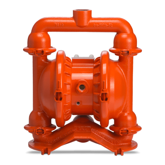
- Page 1 ENGINEERING OPERATION & MAINTENANCE P4 Clamped Metal Pump Where Innovation Flows WIL-10183-E-03...
-
Page 2: Table Of Contents
Contents Section 1: Precautions - Read First! Section 2: Wilden Pump Designation System Section 3: How It Works Section 4: Dimensional Drawings Section 5: Performance P4 Me tal R ubb er - F itt ed P4 Me tal T P E- F i tte d P4 Me tal R edu ce d Str oke PT F E - F itt ed P4 Me tal Fu ll S tro ke PT F E - F itt ed P4 Me tal U ltr a - Fl ex ™... - Page 3 PSG, a Dover Company, except as described by the terms of those agreements. This is a non-contractual document. 01-2019.
-
Page 4: Section 1: Precautions - Read First
Section 1 Precautions - Read First! WARNING: Always wear safety glasses when CAUTION: Do not exceed 82°C (180°F) air operating a pump to avoid eye injury. If diaphragm inlet temperature for all models. rupture occurs, material being pumped maybe forced CAUTION: Thoroughly flush pumps before installing out of the air exhaust. -
Page 5: Section 2: Wilden Pump Designation System
Section 2 W I L D E N P U M P D E S I G N A T I O N S Y S T E M P4 METAL LEGEND / X X X X X / XXX / XX / X XX / XXXX O-RINGS MODEL... -
Page 6: Section 3: How It Works
HOW IT WORKS — PUMP Section 3 The Wilden diaphragm pump is an air-operated, placement, self-priming pump. These drawings show the flow pattern through the pump upon its initial stroke. It is assumed the pump has no fluid in it prior to its initial stroke. FIGURE 1 The air valve directs pressurized FIGURE When... -
Page 7: Section 4: Dimensional Drawings
Section 4 DIMENSIONAL DRAWING P4 Metal DIMENSIONS ITEM METRIC (mm) STANDARD (inch) 14.5 16.9 12.6 10.3 13.3 LW0338 REV. A P4 Metal Saniflo DIMENSIONS ITEM METRIC (mm) STANDARD (inch) 15.6 17.4 12.6 10.3 LW0339 REV. A ® Wilden WIL-10183-E-03... -
Page 8: Section 5: Performance
Section 5 PERFORMANCE P4 METAL RUBBER-FITTED Ship Weight ..Aluminum 13 kg (29 lb) 316 Stainless Steel 20 kg (45 lb) Cast Iron 22 kg (49 lb) Alloy C 23 kg (51 lb) Air Inlet........19 mm (3/4") Inlet ........38 mm (1-1/2") Outlet ......... -
Page 9: P4 Metal Reduced Stroke Ptfe-Fitted
PERFORMANCE P4 METAL REDUCED STROKE PTFE-FITTED Ship Weight ..Aluminum 13 kg (29 lb) 316 Stainless Steel 20 kg (45 lb) Cast Iron 22 kg (49 lb) Alloy C 23 kg (51 lb) Air Inlet........19 mm (3/4") Inlet ........38 mm (1-1/2") Outlet ......... -
Page 10: P4 Metal Ultra-Flex -Fitted
PERFORMANCE P4 METAL ULTRA-FLEX -FITTED Ship Weight ..Aluminum 13 kg (29 lb) 316 Stainless Steel 20 kg (45 lb) Cast Iron 22 kg (49 lb) Alloy C 23 kg (51 lb) Air Inlet........13 mm (1/2") Inlet ........38 mm (1-1/2") Outlet ......... -
Page 11: Su Ct Ion - Li Ft Cur Ve S
S U C T I O N L I F T C U R V E S P4 METAL SUCTION - LIFT CAPABILITY Suction-lift curves are calibrated for pumps operating at 305 m (1,000') above sea level. This chart is meant to be a guide only. -
Page 12: Section 6: Suggested Installation, Operation
Section 6 Suggested Installation, Operation, Maintenance and Troubleshooting Wilden pumps are designed to meet the performance requirements of • Piping: Final determination of the pump site should not be made even the most demanding pumping applications. They have been until the piping challenges of each possible location have been designed and manufactured to the highest standards and are available evaluated. - Page 13 Suggested Installation, Operation, Maintenance and Troubleshooting regulate air pressure. A needle valve is used to regulate volume. NOTE: In the event of a power failure, close the shut- Pump discharge rate also can be controlled by throttling the pump off valve if you do not want the pump to restart when the discharge by partially closing a valve in the discharge line of the power returns.
- Page 14 Suggested Installation, Operation, Maintenance and Troubleshooting Troubleshooting Pump will not run or runs slowly. 3. Check for sticking ball check valves. 1. Remove plug from pilot spool exhaust. 2. Ensure that the air inlet pressure is at least 0.4 bar (5 psig) If material being pumped is not compatible with pump above startup pressure and that the differential pressure elastomers, swelling may occur.
-
Page 15: Section 7: Disassembly / Reassembly
Section 7 Disassembly / Reassembly Pump Disassembly CAUTION: Before any maintenance or repair is attempted, the compressed air line to the pump should be disconnected and all air pressure allowed to bleed Tools Required: from the pump. Disconnect all intake, discharge and air lines. Drain the pump •... - Page 16 Disassembly / Reassembly Step 4 Step 5 Step 6 Remove the discharge valve balls and Using a 1/2" wrench, remove the two Lift liquid chambers and center section from (2) large clamp bands which fasten the intake manifold to expose intake valve balls seats from the liquid chambers and inspect and seats.
- Page 17 Disassembly / Reassembly Step 9B Step 10 2) The outer piston, diaphragm and inner To remove diaphragm assembly from shaft, secure shaft with soft jaws piston separate from the shaft which remains connected to the opposite side (a vise fitted with plywood, plastic or other suitable material) to ensure shaft is diaphragm assembly.
-
Page 18: Air Valve / Center Section Disassembly
Disassembly / Reassembly Air Valve / Center Section Disassembly Tools Required: CAUTION: Before any maintenance or repair is attempted, the compressed air line to the pump should be disconnected and all air pressure allowed to bleed from the pump. Disconnect all intake, •... - Page 19 Disassembly / Reassembly Step 4 Step 5 Step 6 Remove air valve end cap to expose air Remove air valve spool from air valve Remove pilot spool retaining snap ring valve spool by simply lifting up on end body by threading one air valve bolt into on both sides of center section with cap once air valve bolts are removed.
- Page 20 Disassembly / Reassembly Step 9 Step 10A Step 10B With O-ring pick, gently remove the O- Check center block shaft seals for signs NOTE: Threaded sleeves (see ring from the opposite side of the of wear. If necessary, remove shaft A above) are removable and notched end of the spool.
-
Page 21: Reassembly Hints & Tips
Disassembly / Reassembly Reassembly Hints & Tips • Stainless bolts should be lubed to reduce the possibility of seizing during Upon performing applicable maintenance to the air tightening. distribution system, the pump can now be reassembled. Please refer to the disassembly instructions for photos and •... - Page 22 Disassembly / Reassembly Shaft Seal Installation Pre-Installation Tools Once all of the old seals have been removed, the inside of the The following tools can be used to aid in the installation of the bushing should be cleaned to ensure no debris is left that may new seals: cause premature damage to the new seals.
-
Page 23: Gasket Kit Installation
Gasket Kit Installation Carefully prepare sealing surfaces by removing all debris and foreign matter from diaphragm bead and all mating surfaces. If necessary, smooth or deburr all sealing surfaces. Mating surfaces must be properly aligned in order to ensure positive sealing characteristics. Step 1 Step 2 Step 3... -
Page 24: Section 8: Exploded View And Parts List
Section 8 EXPLODED VIEW AND PARTS LISTING P4 METAL EXPLODED VIEW FULL - STROKE DIAPHRAGM - FITTED ® Wilden WIL-10183-E-03... - Page 25 Exploded View and Parts List P4/AAPP P4/ WAPP P4/SAPP P4/SAPP/070 Part Description Qty. Pro-Flo Air Valve Assembly 04-2000-20-700 04-2000-20-700 04-2000-20-700 04-2000-20-700 ® O-Ring (-225), End Cap (1.859 x .139) 04-2390-52-700 04-2390-52-700 04-2390-52-700 04-2390-52-700 End Cap, Pro-Flo 04-2330-20-700 04-2330-20-700 04-2330-20-700 04-2330-20-700 ®...
-
Page 26: P4 Me Tal R Edu Ce D - Stro Ke Di Aphr Agm - F It Ted
Exploded View and Parts Listing P4 METAL EXPLODED VIEW REDUCED - STROKE DIAPHRAGM- FITTED ® Wilden WIL-10183-E-03... - Page 27 Exploded View and Parts List P4/AAPP P4/ WAPP P4/SAPP P4/SAPP/0070 Part Description Qty. Pro-Flo Air Valve Assembly 04-2000-20-700 04-2000-20-700 04-2000-20-700 04-2000-20-700 ® O-Ring (-225), End Cap (1.859 x .139) 04-2390-52-700 04-2390-52-700 04-2390-52-700 04-2390-52-700 End Cap, Pro-Flo 04-2330-20-700 04-2330-20-700 04-2330-20-700 04-2330-20-700 ®...
- Page 28 Exploded View and Parts Listing P4 METAL SANIFLO™ EXPLODED VIEW 1935 / 2004 / EC ® Wilden WIL-10183-E-03...
- Page 29 Exploded View and Parts List P4/SSPPP/ P4/SSPPP/ Item Description Qty. Item Description Qty. 1935/2004/EC 1935/2004/EC Ultra-Flex Components Air Distribution Components Air Valve Assembly, Pro-Flo 04-2000-20-700 Shaft 04-3830-03-700 End Cap 04-2330-20-700 Stud, Shaft (3/8-16 x 1-1/2”) 04-6152-08 O-Ring (-225), End Cap (Ø1.859” x Ø.139”) 04-2390-52-700 Piston, Inner 04-3760-01-700...
-
Page 30: P4 Metal Saniflo™ 1935/2004/Ec
Elastomer Options P4 Metal Ultra-Flex™ Reduced-Stroke Backup Full-Stroke Backup Material Diaphragms (2) Valve Balls (4) Valve Seats (4) Valve Seat O-Rings (4) Diaphragms (2) Diaphragms (2) Diaphragms (2) Neoprene 04-1010-51 04-1020-51 04-1060-51 04-1080-51 04-1120-51* Buna-N 04-1010-52 04-1020-52 04-1080-52 04-1120-52* 04-1010-53 04-1020-53 04-1080-53 04-1120-53*... - Page 31 WIL-10183-E-03 ® Wilden...
- Page 32 22069 Van Buren Street Grand Terrace, CA 92313-5651 USA 1 (909) 422-1730 • F: 1 (909) 783-3440 psgdover.com Where Innovation Flows ® reserves right to modify information and illustrations contained this document without prior notice. This is non-contractual document. 05- 2018 WIL-10183-E-03 ®...
Need help?
Do you have a question about the PSG Wilden PRO-FLO P4 Series and is the answer not in the manual?
Questions and answers