Table of Contents
Advertisement
Quick Links
Advertisement
Table of Contents

Related Manuals for Omron Adept Viper s1300


Summary of Contents for Omron Adept Viper s1300
- Page 1 Omron Adept Viper s1300 Robot User’s Guide...
-
Page 2: Table Of Contents
Adept Viper s1300™ Robots ........ - Page 3 Index ............59 Adept Viper s1300 Robot User’s Guide, Rev B...
- Page 4 Figure 2-7. Moment of Inertia Calculation Examples ........31 Figure 3-1. System Cable Diagram for Adept Viper s1300 Robot ......33 Figure 3-2.
-
Page 5: Introduction
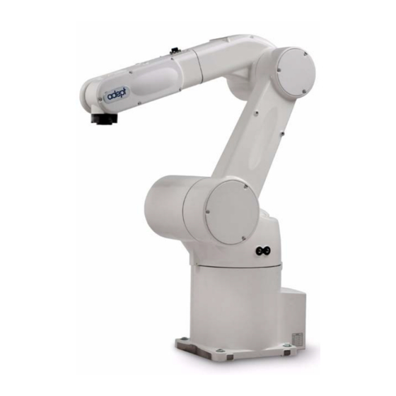
Product Description Adept Viper s1300™ Robots The Adept Viper s1300 is a high-performance, six-axis robot designed specifically for assembly applications. The speed and precision of the Adept Viper robots also make them ideal for material handling, packaging, machine tending, and many other operations requiring fast and precise automation. -
Page 6: Adept Smartcontroller Cx
Adept Viper s1300 robot systems. The J and K amplifiers in the Adept Viper s1300 robot system are controlled by the sDAI (100 W) distributed control module. The sDAI module resides in the PA-4 chassis and contains a RISC microprocessor and interface circuitry that close the servo loops for high- performance robot motion. -
Page 7: Dangers, Warnings, Cautions, And Notes
This indicates a situation which, if not avoided, could result in damage to the equipment. NOTE: Notes provide supplementary information, emphasize a point or procedure, or give a tip for easier operation. Adept Viper s1300 Robot User’s Guide, Rev B... -
Page 8: Safety Precautions
Chapter 1 - Introduction Safety Precautions DANGER: The Adept Viper s1300 robot can cause serious injury or death, or damage to itself and other equipment, if the following safety precautions are not observed: • All personnel who install, operate, teach, program, or maintain the system must... -
Page 9: Intended Use Of The Robots
1. Click on the appropriate .zip file. You are prompted to Open or Save the file. 2. Click Open to open the file and display the archive contents. 3. Double-click on a .pdf file to open it. Adept Viper s1300 Robot User’s Guide, Rev B... -
Page 10: How Can I Get Help
• WEEE/RoHS, Policy: ftp://ftp1.adept.com/Download-Library/Regulatory/ • WEEE Drop-off Sites: http://www.adept.com/contact/americas http://www.adept.com/contact/asiapacific-rim http://www.adept.com/contact/europe The Download Center (ID # 500080) provides Adept WEEE/RoHS Policy. The Contact area of the web site gives locations of WEEE drop-off sites. Adept Viper s1300 Robot User’s Guide, Rev B... -
Page 11: Related Manuals
How Can I Get Help? Related Manuals This manual covers the installation, operation, and maintenance of an Adept Viper s1300 robot system. There are additional manuals that cover programming the system, reconfiguring installed components, and adding other optional components. See Table 1-2. -
Page 12: Robot Installation
Inspect each item for external damage as it is removed from its container. If any damage is evident, contact Adept (see Section 1.9 on page 14). Retain all containers and packaging materials. These items may be necessary to settle claims or, at a later date, to relocate equipment. Adept Viper s1300 Robot User’s Guide, Rev B... -
Page 13: Environmental And Facility Requirements
Installation conditions Grounding resistance: 100 milliohms or less Figure 2-3 on page Adept Viper s1300 Robot User’s Guide, Rev B... -
Page 14: Transporting The Robot
Passing them through other sections may drop the robot unit, resulting in injuries to personnel or damage to the robot. Wire (Belt sling) Waste Cloth Eyebolts Robot Mounting Bolts Figure 2-1. Robot in Hoisting Sling Adept Viper s1300 Robot User’s Guide, Rev B... -
Page 15: Transport Procedure
When the robot unit is first unpacked, this job is not required. As shown at right, mount the eyebolts. When delivered, the robot unit is packed with eyebolts attached, so this job is not required Eyebolts Adept Viper s1300 Robot User’s Guide, Rev B... - Page 16 Section 2.4 on page Remove the eyebolts from the robot Caution: Before running the robot unit, be unit. sure to remove the eyebolts. Otherwise, the robot arm will strike against those eyebolts. Adept Viper s1300 Robot User’s Guide, Rev B...
-
Page 17: Mounting The Robot
5. Secure the robot unit to the mount with four bolts and plain washers. • Bolt: M12 x 40 mm (strength class: 12.9) • Tightening torque: 110 +/- 22 Nm • Plain washer: JIS B 1256 (polished round) Adept Viper s1300 Robot User’s Guide, Rev B... -
Page 18: Grounding The Robot
A I R 1 C N 2 2 C N 2 0 A I R 2 Grounding Terminal (M5) User-Supplied Ground Wire 5.5mm or more Figure 2-3. Ground Point on Robot Adept Viper s1300 Robot User’s Guide, Rev B... -
Page 19: Description Of Connectors On Robot Interface Panel
Section 2.7 on page AIR 2 - air piping connector (BSPT1/4), connects directly to AIR 2 on the second (upper) arm. Grounding Terminal - ground point on robot, see Section 2.5 on page Adept Viper s1300 Robot User’s Guide, Rev B... -
Page 20: Air Lines And Signal Wiring
Note 2: Use the supplied connector sets for CN20 and CN21. SRCN6A25-24S (round type connector) for CN20 (Japan Aviation Electronics Industry Ltd) 05019-000 JMLP1610M for CN21 (L type plug connector) DDK Electronics, Inc. Adept Viper s1300 Robot User’s Guide, Rev B... -
Page 21: Optional Solenoid Cable
Input 1005 Ground Inputs 1001 to 1005 are preconfigured as low-active (sinking) inputs. Outputs 0007 and 0008 are preconfigured as high-side (sourcing) outputs. Limited to a combined total of 1A of current. Adept Viper s1300 Robot User’s Guide, Rev B... -
Page 22: Solenoid Valve Specifications
-5 to 50 degrees C (No dew condensation allowed. When dry air is used) Solenoid Operating voltage 24 V ±10% Power consumption (current) 0.65 W (27 mA) Surge voltage protection circuit Diode Adept Viper s1300 Robot User’s Guide, Rev B... -
Page 23: External Mounting Locations On Robot
Chapter 2 - Robot Installation External Mounting Locations on Robot 2 M4 12 deep 2 M6 18 deep 2 M6 18 deep 2 M12 34 deep Figure 2-5. External Mounting Holes on Robot Adept Viper s1300 Robot User’s Guide, Rev B... -
Page 24: Designing End-Effectors
Figure 2-6. Center of rotation of J5 Allowable range of center of gravity position Center of rotation of J4 and J6 Figure 2-6. Allowable Range of Center of Gravity Position of End-effector Adept Viper s1300 Robot User’s Guide, Rev B... -
Page 25: Moment Of Inertia Around J4, J5 And J6
Inertia moment around center of gravity 3. Rectangular parallelepiped (The axis of rotation passes through the center of gravity.) ❲kgm ❳ l: Moment of inertia ❲kg❳ m: Mass ❲m❳ r: Radius ❲m❳ b, c, : Length Adept Viper s1300 Robot User’s Guide, Rev B... -
Page 26: Figure 2-7. Moment Of Inertia Calculation Examples
(from 2 and 5 in Table 2-3) ((0.08 + 0.01 + 0.05) +0.05 2.30 × 10 [kgm Moment of inertia around J4 and J5 of entire end-effector: I 2.54×10 [kgm Figure 2-7. Moment of Inertia Calculation Examples Adept Viper s1300 Robot User’s Guide, Rev B... -
Page 27: System Installation
380-415 VAC 3-Phase User-Supplied Power Supply Front Panel T2 Pendant (optional) Adept Viper s1300 Robot User-supplied PC running AdeptWindows Grounding Terminal User-Supplied Ground Wire Figure 3-1. System Cable Diagram for Adept Viper s1300 Robot Adept Viper s1300 Robot User’s Guide, Rev B... -
Page 28: Installing The Smartcontroller
The Adept SmartController motion controller must be connected to a user-supplied PC or the Adept SmartVision EX processor for setup, control, and programming. • Connect an Ethernet crossover cable between the PC and the SmartController motion controller Adept Viper s1300 Robot User’s Guide, Rev B... -
Page 29: Installing The Pa-4 Power Chassis
XSLV connector on the sDAI module, and tighten the latching screws. 5. Install the Arm Power/Signal cable between the CN22 connector on the robot and the Arm Power/Signal connector on the PA-4. Adept Viper s1300 Robot User’s Guide, Rev B... -
Page 30: Figure 3-2. Adept Pa-4 Power Chassis With Sdai Module
Figure 3-2. Adept PA-4 Power Chassis with sDAI Module NOTE: In Adept Viper s1300 systems, the sDAI module must be a 100 W version. A standard sDAI will not work. Adept Viper s1300 Robot User’s Guide, Rev B... -
Page 31: Connecting 3-Phase Ac Power To Pa-4
Adept PA-4 Power Chassis User’s Guide. versa WARNING: Verify the voltage settings are correct before turning on power. Operating the Adept PA-4 power chassis with incorrect voltage settings can cause damage or injury. Adept Viper s1300 Robot User’s Guide, Rev B... -
Page 32: Connecting The Pa-4 3-Phase Ac Power Cord To Ac Supply
To ensure electrical-shock protection, the ground conductor must be connected to a properly grounded power source. WARNING: Ensure that a proper protective ground connection exists before turning on the power. Adept Viper s1300 Robot User’s Guide, Rev B... -
Page 33: Typical 3-Phase Ac Power Installation Diagrams
3Ø 200–240V~ Adept PA-4 3Ø 200–240V~ Figure 3-3. Typical 3-Phase 200-240 VAC Connection for PA-4 System 3Ø 380–415V~ Adept PA-4 3Ø 380–415V~ Figure 3-4. Typical 3-Phase 380-415 VAC Connection for PA-4 System Adept Viper s1300 Robot User’s Guide, Rev B... -
Page 34: System Operation
• User-supplied ground wire between the SmartController and ground. • XSYS cable between the robot interface panel XSLV safety interlock connector and XSYS connector on the SmartController, and the latching screws tightened. Adept Viper s1300 Robot User’s Guide, Rev B... -
Page 35: User-Supplied Safety Equipment Checks
The Front Panel, which is mounted just outside the workcell safety barrier, is shown in the following figure. If enabled, the High Power button must be pressed while blinking (default time-out is 10 seconds). If the button stops blinking, you must enable power again. Adept Viper s1300 Robot User’s Guide, Rev B... -
Page 36: Verifying E-Stop Functions
• V+ Language User’s Guide • V+ Language Reference Guide • V+ Operating System Reference Guide NOTE: When using an Adept pendant with an Adept Viper robot, the Free Mode is disabled for safety reasons. Adept Viper s1300 Robot User’s Guide, Rev B... -
Page 37: Connecting Digital I/O To The System
1 2 3 4 XDIO XUSR XSYS XMCP XDC1 XDC2 adept technology, inc. XDIO Connector 12 Input signals: 1001 to 1012 8 Output signals: 0001 to 0008 Figure 4-2. Connecting Digital I/O to the System Adept Viper s1300 Robot User’s Guide, Rev B... - Page 38 IO Blox 2 Inputs 1121 - 1128 Outputs 0113 - 0120 IO Blox 3 Inputs 1129 - 1136 Outputs 0121 - 0128 IO Blox 4 Inputs 1137 - 1144 Outputs 0129 - 0136 Adept Viper s1300 Robot User’s Guide, Rev B...
-
Page 39: Status Panel Codes On Sdai Module
For more information on status codes, go to the Adept Document Library on the Adept website, and in the Procedures, FAQs, and Troubleshooting section, look for the Adept Status Code Summary document. Adept Viper s1300 Robot User’s Guide, Rev B... -
Page 40: Installing And Using The Brake Release Box
Axis selector switch 2 3 4 Status LED BRAKE RELEASE Brake Release Pushbutton 15-pin male D-Sub connector Figure 4-3. Manual Brake Release Box Adept Viper s1300 Robot User’s Guide, Rev B... -
Page 41: Maintenance
3. Remove the cover from the robot unit. See Figure 5-1. Connector Plate Battery Support Plate Figure 5-1. Removing Cover to Replace Encoder Batteries 4. Pull out the battery support plate. See Figure 5-2. Adept Viper s1300 Robot User’s Guide, Rev B... -
Page 42: Figure 5-2. Removing Battery Support Plate
NOTE: Do not disconnect old backup batteries before connecting a new one to the pin from which the dummy connector cap is removed. If you do so, the encoder positional data may be lost. Adept Viper s1300 Robot User’s Guide, Rev B... -
Page 43: Figure 5-4. Connecting First New Battery
Otherwise, the battery service life will be reduced. 8. Disconnect the old backup battery that is next to the new battery connected in Step 7, and then connect a new battery (3rd one). See Figure 5-6. Adept Viper s1300 Robot User’s Guide, Rev B... -
Page 44: Figure 5-6. Connecting Third New Battery
Dummy connector cap Old battery Battery holder New battery (3rd one) Figure 5-7. Reconnecting Dummy Connector Cap 10. Secure the battery support plate to the connector plate. Tightening torque: 1.6 +/- 0.3 Nm Adept Viper s1300 Robot User’s Guide, Rev B... -
Page 45: Installing User-Supplied Hardstops
If you need information on modifying hardstops, please contact Adept. CAUTION: Failures caused by user-supplied hardstops are not covered by the warranty, even if the robot is under warranty. Adept Viper s1300 Robot User’s Guide, Rev B... -
Page 46: Technical Specifications
Technical Specifications Robot Dimensions 84.53 120.0° R223.45 120.0° R598 1593.41 90.0° R795.38 1153 135.0° 135.0° R1118.41 491.11 R598 R598.41 Figure 6-1. Adept Viper s1300 Side Dimensions and Work Envelope Adept Viper s1300 Robot User’s Guide, Rev B... -
Page 47: Figure 6-2. Adept Viper S1300 Top Dimensions And Work Envelope
Chapter 6 - Technical Specifications 170.0° R1298 R403.45 170.0° Figure 6-2. Adept Viper s1300 Top Dimensions and Work Envelope Adept Viper s1300 Robot User’s Guide, Rev B... -
Page 48: Robot Flange Dimensions
Robot Flange Dimensions Robot Flange Dimensions 90° Ø50 0.000 -0.039 45° +0.012 Ø6 0.000 Ø25 +0.021 4x M6 0.000 Ø40 Bolt circle Figure 6-3. Robot Flange Dimensions Adept Viper s1300 Robot User’s Guide, Rev B... -
Page 49: Specifications
IP-40 Weight Approx. 78 kg Note 1: Position repeatability is the value at constant ambient temperature. Note 2: Only the 4x6 air piping system may be controlled by built-in solenoid valves. Ø Adept Viper s1300 Robot User’s Guide, Rev B... -
Page 50: Index
PA-4 power chassis robot current/voltage ratings SmartController power chassis, 3-phase system, overview Customer Service assistance verifying intended use of the robot interface box location on PA-4 interface panel on robot Adept Viper s1300 Robot User’s Guide, Rev B... - Page 51 XSYS cable, installing s1300 dimensions, side view s1300 dimensions, top view solenoids, signal wiring transporting unpacking and inspection robot flange, dimensions Adept Viper s1300 Robot User’s Guide, Rev B...
- Page 52 Omron Adept Technologies, Inc. Tel: 925-245-3400 Email: info@adept.com omron247.com Specifications subject to change without notice. 2016 Omron. ALL RIGHTS RESERVED. Pub Number R94I-E-01 P/N: 06561-000, Rev B...
Need help?
Do you have a question about the Adept Viper s1300 and is the answer not in the manual?
Questions and answers