Table of Contents
Advertisement
Quick Links
Advertisement
Table of Contents

Subscribe to Our Youtube Channel
Related Manuals for Omron SCARA XE Series


Summary of Contents for Omron SCARA XE Series
-
Page 3: Table Of Contents
CONTENTS XE series Maintenance Manual Warranty Chapter 1 Introduction 1. Introduction 1.1 Available manuals 1.2 Signal symbols 2. Before using the robot (Be sure to read the following notes.) Chapter 2 Attaching, detaching, and replacing the cover 1. Attaching, detaching, and replacing the cover Chapter 3 Periodic inspection 1. - Page 4 CONTENTS XE series Maintenance Manual Chapter 5 Replacing the harmonic drive 1. Cautions on replacement of the harmonic drive 2. Replacement procedure for harmonic drive R6YXE400 2.1 Replacing the X-axis harmonic drive 2.1.1 Preparation 2.1.2 Removal 2.1.3 Replacement and reassembly 2.1.4 Aging 5-10...
- Page 5 CONTENTS XE series Maintenance Manual Chapter 8 Replacing the Z-axis drive unit 1. Replacing the Z-axis drive unit R6YXE400 1.1 Replacing the Z-axis motor 1.2 Replacing the Z-axis belt 1.3 Replacing the Z-axis ball screw 1.4 Replacing the Z-axis brake 2.
-
Page 7: Warranty
OF PROFITS OR COMERCIAL LOSS IN ANY WAY CONNECTED WITH THE PRODUCTS, WETHER SUCH CLAIM IS BASED ON CONTRACT, WARRANTY, NEGLIGENCE OR STRICT LIABILITY. In no event shall the responsibility of OMRON for any act exceed the individual price of the product on which liability is asserted. -
Page 9: Chapter 1 Introduction
Chapter 1 Introduction Contents 1. Introduction Available manuals Signal symbols 2. Before using the robot (Be sure to read the following notes.) 1-3... -
Page 11: Available Manuals
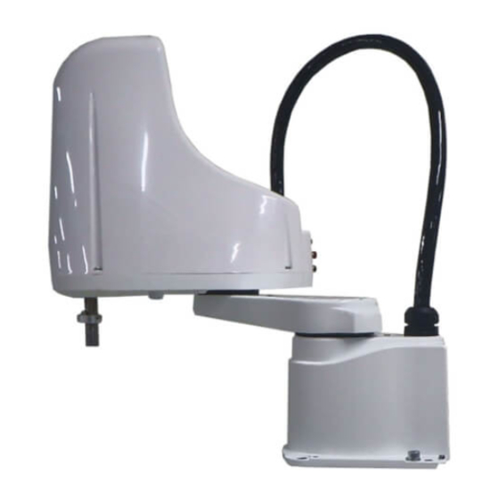
Introduction The OMRON XE series robots are SCARA type industrial robots developed based on years of OMRON experience and achievements in the automation field as well as efforts to streamline our in-house manufacturing systems. The XE series robots have a two-joint manipulator consisting of an X-axis arm and a Y-axis arm, and are further equipped with a vertical axis (Z-axis) and a rotating axis (R-axis) at the tip of the manipulator. -
Page 12: Signal Symbols
Signal symbols The following safety alert symbols and signal words are used to provide safety instructions that must be observed and to describe handling precautions, prohibited actions, and compulsory actions. Make sure to understand the meaning of each symbol and signal word and then read this manual. DANGER This indicates an immediately hazardous situation which, if not avoided, will result in death or serious injury. -
Page 13: Before Using The Robot (Be Sure To Read The Following Notes.)
Before using the robot (Be sure to read the following notes.) At this time, our thanks for your purchase of this OMRON XE series SCARA robot. NOTE In the YRCX controller, axis names are called using numeric values, like axis-1, axis-2, axis-3, and so on. In this manual, axis names are called using alphabetic characters, like X-axis, Y-axis, Z-axis, and so on. - Page 15 Chapter 2 Attaching, detaching, and replacing the cover Contents 1. Attaching, detaching, and replacing the cover...
-
Page 17: Attaching, Detaching, And Replacing The Cover
To prevent such troubles, strictly observe this caution. R6YXE400 Y-axis arm cover (OMRON’s part No. KDS-M1314-10) Harness cover (OMRON’s part No. KDS-M1312-10) Harness cover mounting bolt Hex socket head bolt M4×10, 7 pcs. - Page 18 R6YXE610 / R6YXE710 Y-axis arm cover (OMRON’s part No. KFS-M1314-00) Harness cover mounting bolt (OMRON’s part No. 91312-03010) M3x10 8 pcs. Washer (OMRON’s part No. 90990-28J204) Harness cover (OMRON’s part No.KDS-M1312-00) Y-axis arm cover mounting bolt Hex socket head bolt.
-
Page 19: Chapter 3 Periodic Inspection
Chapter 3 Periodic inspection Contents 1. Over view 2. Daily inspection 3. Six-month inspection 4. Applying the grease Applying the grease to the spline shaft Applying the grease to the ball screw... -
Page 21: Overview
Overview Daily and periodic inspection of the OMRON robot is essential in order to ensure safe and efficient operation. This chapter describes the periodic inspection items and procedures for the OMRON XE series robots. Periodic inspection includes: • Daily inspection •... -
Page 22: Daily Inspection
Daily inspection The following is an inspection list that must be performed every day before and after operating the robot. Inspection to be performed with the controller turned off ■ Step1 Turn off the controller. Step2 Place a sign indicating the robot is being adjusted. Place a sign indicating the robot is being inspected, to keep others from operating the controller switch. -
Page 23: Six-Month Inspection
• Do not attempt to weld, heat up, drill holes or cut this container. This might cause the container to explode and the remaining materials inside it to ignite. CAUTION Unless grease specified by OMRON is used, the service life of the ball screw and ball spline will shorten. - Page 24 Inspection to be performed with the controller turned off ■ Step1 Turn off the controller. Step2 Place a sign indicating the robot is being adjusted. Place a sign showing that the robot is being inspected, to keep others from operating the controller switch.
- Page 25 If no cause is found, contact your distributor. • Check the fan cover for contamination. If contaminated, replace the fan filter. (Refer to the User’s Manual for OMRON Robot Controller.) Adjustment and parts replacement ■...
-
Page 26: Applying The Grease
Applying the grease Applying the grease ■ Name Manufacturer Remarks L100 THK. Co., Ltd. Applying the grease to the spline shaft Follow the steps below to apply the grease to the spline shaft. Step1 Turn off the controller power. Step2 Place a sign indicating the robot is being adjusted. -
Page 27: Applying The Grease To The Ball Screw
Applying the grease to the ball screw Follow the steps below to apply the grease to the ball screw. WARNING Before starting the work, thoroughly read “1. Attaching, detaching, and replacing the cover” in Chapter 2. Step1 Turn off the controller power. Step2 Place a sign indicating the robot is being adjusted. - Page 28 R6YXE610 R6YXE710 Applying the grease Cover bolt Apply the grease to the Apply the grease to the groove thinly. groove thinly. 53312-FV-00...
- Page 29 Chapter 4 Adjusting the origin Contents 1. Adjusting the machine reference value Stroke end method 1.1.1 Changing the X-axis reference value R6YXE400 1.1.2 Changing the Y-axis reference value R6YXE400 1.1.3 Changing the Z-axis and R-axis reference values Sensor method (X-axis, Y-axis) 1.2.1 Adjusting the X-axis machine reference 1.2.2...
-
Page 31: Adjusting The Machine Reference Value
Adjusting the machine reference value The X- and Y-axis origin positions of the XE series are fixed and cannot be changed. Additionally, the machine reference value was correctly adjusted at shipment. The readjustment is not needed during normal operation. However, if the machine reference value exceeds the return-to-origin tolerance range for some reason, follow the steps below to readjust the machine reference value. -
Page 32: Changing The X-Axis Reference Value R6Yxe400
Replace the bolts one-by-one and take great care so that the speed reduction gear and arm do not deviate. Bolt M3 x 35, (OMRON’s part No.: 91312-03035) 12 pcs. Step10 Secure the speed reduction gear. Secure the speed reduction gear while referring to “2.1 Replacing the X-axis harmonic drive” in Chapter 5. -
Page 33: Changing The Z-Axis And R-Axis Reference Values
1.1.3 Changing the Z-axis and R-axis reference values Step7 Remove the cover. Remove the cover while referring to "12. Detaching or attaching the covers" in Chapter 2. R6YXE400 R6YXE610 R6YXE710 Step 7 Step 7 Removing the cover Removing the cover Hex socket head bolt Hex socket head bolt Washer... - Page 34 Step9 Loosen the bolts that secure the motor installation plate. R6YXE400 Step 9 Removing the plate To adjust the Z-axis reference value, Z-axis fixing plate loosen the bolts at 3 locations. Z-axis motor R-axis fixing plate To adjust the R-axis reference value, loosen the bolts at 3 locations.
- Page 35 Step12 Go out of the safety enclosure. Step13 Turn on the controller. Check that no one is inside the safety enclosure, and then turn on the controller. Step14 Perform the return-to-origin of the Z-axis. NOTE For details about how to perform the return-to-origin, refer to "2.3 Return-to-origin procedures" in this Chapter. Step15 Check the Z-axis machine reference value.
-
Page 36: Sensor Method (X-Axis, Y-Axis)
Sensor method (X-axis, Y-axis) 1.2.1 Adjusting the X-axis machine reference CAUTION • The origin position may change due to machine reference adjustment. If it occurs, you must set point data again. • When the return-to-origin direction is reversed, the origin position may not be the base front. When using the standard soft limit, the axis may collide with the mechanical stopper. - Page 37 Step8 Loosen the hex nut. Step 8-10 Adjusting the X-axis machine reference value Using the wrench, loosen the hex nut that secures the X-axis origin sensor. 23307-FV-00 X-axis origin sensor CAUTION It is enough to loosen the nut. Do not remove the nut completely.
-
Page 38: Adjusting The Y-Axis Machine Reference
1.2.2 Adjusting the Y-axis machine reference CAUTION The origin position may change due to machine reference adjustment. If it occurs, you must set point data again. Follow the steps below to adjust the Y-axis machine reference value. Prepare a wrench for a width across flat of 13 mm. Step1 Turn on the controller. - Page 39 Step8 Loosen the hex nut. Step 8-10 Adjusting the Y-axis machine reference value Using the wrench, loosen the hex nut that secures the Y-axis origin sensor. 23308-FV-00 CAUTION It is enough to loosen the nut. Do not remove the nut completely. Step9 Move the Y-axis origin sensor as follows.
-
Page 40: Mark Method R6Yxe400
• When pressing the key on the execution confirmation screen, the execution of the absolute reset is canceled. • For details about how to operate the robot controller, see the "OMRON Robot Controller User's Manual". Step1 Turn on the controller. - Page 41 Step6 Select an axis whose absolute reset is performed. Use the cursor keys ( ) to select an axis number whose absolute reset is performed, and then press The execution confirmation screen will pop up. Step7 Perform the step movement. Press the jog key to perform the step movement of the robot until the origin position marks are matched with each other.
-
Page 42: Absolute Reset In Servo Off State (Re-Reset)
• When pressing the key on the execution confirmation screen, the execution of the absolute reset is canceled. • For details about how to operate the robot controller, see the "OMRON Robot Controller User's Manual". Step1 Turn on the controller. - Page 43 Step6 Move the arm to the position where the origin position marks are matched with each other. Press the emergency stop button on the PBEX to put the robot in the emergency stop state. WARNING Be sure to press the emergency stop button and move the robot in the state where the servo on cannot be operated from the outside.
- Page 44 Step8 Select an axis whose absolute reset is performed. Use the cursor keys ( ) to select an axis number whose absolute reset is performed, and then press The execution confirmation screen will pop up. CAUTION • There are multiple discrete positions where the absolute reset can be performed. Move the robot step-by-step while referring to the PBEX screen.
-
Page 45: Absolute Reset In Servo On State (New Reset)
Move to the all-axis 0 pulse position. When the absolute reset has been completed, move the robot to the all-axis 0 pulse position. For details about how to move to the 0 pulse position, refer to the "OMRON Robot Controller User's Manual". CAUTION Before affixing the origin position stickers, be sure to move the robot to the all axes "0"... - Page 46 Step10 Affix the origin position stickers. After the robot has been moved to the all axes "0" pulse position, press the emergency stop button and affix the origin position stickers to legible positions. After that, these origin position stickers are used to perform the absolute reset again at the same position.
-
Page 47: Absolute Reset In Servo Off State (New Reset)
• When pressing the key on the execution confirmation screen, the execution of the absolute reset is canceled. • For details about how to operate the robot controller, see the "OMRON Robot Controller User's Manual". Step1 Turn on the controller. - Page 48 Step11 Affix the origin position stickers. After the robot has been moved to the all-axis 0 pulse position, press the emergency stop switch and affix the origin position stickers supplied with the robot to easy-to-identify positions near the R-axis rotation part so that they can be used when the absolute reset is performed again at the same position.
-
Page 49: Chapter 5 Replacing The Harmonic Drive
Chapter 5 Replacing the harmonic drive Contents 1. Cautions on replacement of the harmonic drive 2. Replacement procedure for harmonic drive R6YXE400 5-2 Replacing the X-axis harmonic drive 2.1.1 Preparation 2.1.2 Removal 2.1.3 Replacement and reassembly 2.1.4 Aging 5-10 Replacing the Y-axis harmonic drive 5-11 2.2.1 Preparation... -
Page 51: Cautions On Replacement Of The Harmonic Drive
• Do not attempt to weld, heat up, drill holes or cut this container. This might cause the container to explode and the remaining materials inside it to ignite. CAUTION The harmonic drive service life may shorten if the grease recommended by OMRON is not used. ■ Recommended grease Use the following harmonic drive grease. -
Page 52: Replacement Procedure For Harmonic Drive R6Yxe400
For the bolt tightening torque in the harmonic drive replacement work, see the Table below. However, when tightening the mounting bolts for the harmonic drive, observe the tightening torque specified in each replacement procedure. Use only OMRON genuine bolts. ■... -
Page 53: Removal
Name Part No. Manufacturer Remarks KANON For M3 set screw Torque screwdriver N12LTDK (Nakamura Mfg. Co., Ltd.) Tightening torque: 0.7Nm (7kgfcm) Attachment hexagonal width across flat: 6.35mm Drive bit 3C1507 Overall length: 70mm (Nagahori Industry Co., Ltd.) Hexagonal width across flat at tip: 1.5mm * Use a commercially available torque wrench to tighten bolts other than those shown above. - Page 54 Step6 Remove the X-axis motor. Step 6 Removing the X-axis motor 53501-FV-00 Step7 Remove the wave generator. 1. Remove the set screw (1 pc.) that secures the wave generator. 2. Remove the wave generator from the motor. 53502-FK-00 O-ring X-axis motor Bolt M5 x 16 Step 7 Removing the wave generator...
- Page 55 Step8 Remove the X-axis arm. Step 8 Removing the X-axis arm 53503-FV-01 Step9 Remove the X-axis harmonic drive from the X-axis arm. 53505-FV-00 O-ring supplied with the harmonic drive NOTE An O-ring is fitted to the X-axis arm. Replace this O-ring with a new one.
-
Page 56: Replacement And Reassembly
2.1.3 Replacement and reassembly Follow the steps below to replace the harmonic drive with a new one and reassemble it. Step1 Perform the work shown below before reassembling the harmonic drive. 1. Install the bolts on the harmonic drive. 2. Remove the bolts that have been assembled and secured temporarily. Step 1 Preparations before assembling the harmonic drive ... - Page 57 Step2 Secure a new harmonic drive to the X-axis arm. 1. Degrease the harmonic drive installation surface of the X-axis arm. Do not apply the grease to the seating part. 2. Fit the O-ring coated with the new harmonic grease into the O-ring groove of the X-axis arm. Since the grease application to the O-ring is intended to prevent the O-ring from coming off, it is accepted to apply a small amount of the grease.
- Page 58 Step4 Fit the new O-ring coated with the Step 4 Installing the harmonic drive harmonic grease into the O-ring groove of the harmonic drive. 1. Degrease the top surface of the plate where the harmonic drive is to be installed. CAUTION Do not allow the O-ring to get caught out of the Degrease the base top surface...
- Page 59 Step7 Fit a new O-ring (3) into the Step 7-8 Securing the wave generator motor flange end face. M3 set screw (Supplied with the harmonic drive.) 53613-FK-00 Apply a small amount of the screw lock. CAUTION Use the tool C. Wave generator Do not allow the O-ring to get caught out of the (Harmonic drive)
-
Page 60: Aging
2.1.4 Aging Step1 Go out of the safety enclosure. Step2 Turn on the controller. Check that no one is inside the safety enclosure, and then turn on the controller. CAUTION After the harmonic drive has been replaced, it is necessary to perform the return-to-origin and set the standard coordinates and point data again. -
Page 61: Replacing The Y-Axis Harmonic Drive
Before starting the work, thoroughly read “1. Attaching, detaching, and replacing the cover” in Chapter 2. The following shows the parts and tools necessary for the Y-axis harmonic drive replacement work. 2.2.1 Preparation Replacement parts Part Name OMRON Part No. Part No. / Specs Q'ty Remarks Harmonic drive KDS-M2510-00 O-ring Cross section diameter: 0.8mm... -
Page 62: Removal
2.2.2 Removal Step 4 Follow the steps below to remove the Y-axis parts. Removing the cover Step1 Turn off the controller. hex socket Step2 Place a sign indicating the robot is head bolt being adjusted. Cover Place a sign indicating the robot is being adjusted, to keep others from operating the controller or operation panel. - Page 63 Step 6 Removing the wave generator Step6 Remove the wave generator from the motor shaft. Remove the set screws (2 pcs.) that secure the wave generator. 53620-FV-00 Step7 Remove the Y-axis harmonic drive from the top surface of the X-axis arm.
-
Page 64: Replacement And Reassembly
2.2.3 Replacement and reassembly Follow the steps below to replace the harmonic Step 1 Preparations before assembling the harmonic drive drive with a new one and reassemble it. Step1 Perform the work shown below Harmonic drive mounting bolts (7) M3 × 8 (4 pcs) before reassembling the harmonic drive. - Page 65 Step2 Secure a new harmonic drive to Step 2 Installing the harmonic drive the X-axis arm. 1. Degrease the harmonic drive New harmonic drive (1) installation surface of the X-axis arm. Remove the temporarily secured bolt later. Do not apply the grease to the seating part.
- Page 66 Step4 Apply the grease to the inside of Applying the grease to the inside of Step 4-6 the harmonic drive main body. the harmonic drive main body For the Y-axis, apply the grease so that it Apply the grease so that it becomes flat.
- Page 67 Step8 Secure the Y-axis arm to the Step 8 Securing the Y-axis arm harmonic drive. 1. Degrease the Y-axis arm side where the harmonic drive is to be installed. 2. Apply the harmonic grease 4B No.2 to the tip of each bolt so that the roots of New Harmonic drive mounting bolt (6) at least the first four threads of the new M3 ×...
- Page 68 Step 9 Tightening the bolts Step9 Tighten the bolts in the bolt tightening order shown below. 1. While rotating the Y-axis arm, gradually tighten the bolts <13> <14> <15>, and <16> in an alternating manner, and in the order indicated below (rotate the arm in ultra-low-speed mode (1/10 of turn per second)).
-
Page 69: Aging
2.2.4 Aging Step1 Go out of the safety enclosure. Step2 Turn on the controller. Check that no one is inside the safety enclosure, and then turn on the controller. CAUTION After the harmonic drive has been replaced, it is necessary to perform the return-to-origin and set the standard coordinates and point data again. -
Page 70: Replacement Procedure For Harmonic Drive R6Yxe610 R6Yxe710
For the bolt tightening torque in the harmonic drive replacement work, see the Table below. However, when tightening the mounting bolts for the harmonic drive, observe the tightening torque specified in each replacement procedure. Use only OMRON genuine bolts. ■... -
Page 71: Removal
Tools(Torque wrench, etc.) CAUTION Use accurately calibrated torque screwdrivers and torque wrenches. Name Part No. Manufacturer Remarks KANON For M5 hex socket head bolt Torque wrench N230QLK (Nakamura Mfg. Co., Ltd.) Tightening torque: 15.2Nm (156kgfcm) KANON Mounting 9.53mm, total length 100mm, Hexagonal width Changeable head 3KH5L (Nakamura Mfg. - Page 72 Step5 Disconnect the connectors of the X-axis motor power wire XM and resolver wire XP in the base, and the round terminal of the X-axis Step 6 Removing the X-axis motor motor. Refer to Chapter 6 “Replacing the machine harness”. Step6 Remove the X-axis motor.
- Page 73 Step9 Remove the wave generator. Step 9 Remove the wave generator. 53533-FV-00 Remove the set screw (1 pc.) that secures the wave generator. wave generator Step10 Removing the harmonic drive Step 10 Removing the harmonic drive 53534-FV-00 Harmonic drive O-ring supplied with the harmonic drive(KN5-M257L-00) Bolt M4 x 20 Removing the ring .
-
Page 74: Replacement And Reassembly
3.1.3 Replacement and reassembly Follow the steps below to replace the harmonic drive with a new one and reassemble it. Step1 Perform the work shown below before reassembling the harmonic drive. 1. Install the bolts on the harmonic drive. 2. Remove the bolts that have been assembled and secured temporarily. Step 1 Preparations before assembling the harmonic drive ... - Page 75 Step2 Secure a new harmonic drive to the X-axis arm. 1. Degrease the harmonic drive installation surface of the X-axis arm. Do not apply the grease to the seating part. 2. Fit the O-ring coated with the new harmonic grease into the O-ring groove of the X-axis arm. Since the grease application to the O-ring is intended to prevent the O-ring from coming off, it is accepted to apply a small amount of the grease.
- Page 76 Step4 Step 4 Install the wave generator. Install the wave generator 53538-FV-00 Wave generator CAUTION Do not allow the O-ring to get caught out of the groove during reassembly. If the robot is operated with the O-ring left caught out of the groove, this may cause a malfunction.
- Page 77 Step 8 Motor Unit Mounting Step8 Fix the motor unit to the base. Use new fixing bolts. Apply 4BNo. 2 grease to at least 4 threads at the end. Degrease the mating surfaces of the motor New bolt 5 holder and base. M5 x 25 (Tools D) 53543-FV-00 Motor unit...
- Page 78 Step11 Secure q X shaft arm and harmonic drive. X Secure the axis arm and harmonic drive. Use new fixing bolts. Apply 4BNo. 2 grease to at least 4 threads at the end. Tighten the bolts in the following tightening order. 1.
-
Page 79: Aging
Step 12 Replacing Base Back Covers Step12 Replace the base cover. 51544-FV-00 Bolt M4×10 Base rear cover Bolt M4×6 3.1.4 Aging Step1 Go out of the safety enclosure. Step2 Turn on the controller. Check that no one is inside the safety enclosure, and then turn on the controller. CAUTION After the harmonic drive has been replaced, it is necessary to perform the return-to-origin and set the standard coordinates and point data again. -
Page 80: Replacing The Y-Axis Harmonic Drive
Before starting the work, thoroughly read “1. Attaching, detaching, and replacing the cover” in Chapter 2. The following shows the parts and tools necessary for the Y-axis harmonic drive replacement work. 3.2.1 Preparation Replacement parts Part Name OMRON Part No. Part No. / Specs Q'ty Remarks Harmonic drive... -
Page 81: Removal
3.2.2 Removal Step 4 Removing the cover Follow the steps below to remove the Y-axis parts. Step1 Turn off the controller. Cover Step2 Place a sign indicating the robot is being adjusted. Bolt Place a sign indicating the robot is being adjusted, to keep others from operating the controller or operation panel. - Page 82 Step6 Y Remove the shaft motor wiring. Step 6 Y motor removal Y Remove the shaft motor wiring. 53620-FV-00 Step7 Remove the motor. Bolted M5x16 O-ring Step8 Y Remove the shaft arm. Step 8 Y motor removal 53549-FV-00 Bolt M3×20 CAUTION Washer Y Removing the shaft arm mounting bolts may...
- Page 83 Step 9 Removing the Wave Generator Step9 Remove the wave generator from the motor shaft. Remove the set screw that secures the wave generator. 53559-FV-00 Step10 Remove the Y-axis harmonic drive Step 10 Removing the Wave Generator from the top surface of the X-axis arm.
-
Page 84: Replacement And Reassembly
3.2.3 Replacement and reassembly Step 1 Prepare 40g of harmonic grease 4BNo. 2 and Preparing to Install Harmonic Drives replace it with a new harmonic drive by following 1. Harmonic Fixing Bolts 9 the procedures below. M3 ×8 4pic Step1 Perform the work shown below before reassembling the harmonic drive. - Page 85 Step2 Secure the new harmonic drive to Step 2 Installing the harmonic drive the X-axis arm. Ring Ring 1. X Degrease the mounting surface of the New harmonic drive (1) New harmonic drive (1) harmonic drive on the shaft arm. Do not apply grease to the seating New O-ring (4) X Degrease the...
- Page 86 Step4 Apply the remaining grease to the Step 4-5 inside of the harmonic unit. Applying grease inside the harmonic body Y On the shaft, apply grease so that it is Apply grease so that it is flat. flat. 53626-FV-00 Harmonic Drive Accessories Harmonic Drive Accessories Step5 Install the new harmonic drive...
- Page 87 Step7 Tighten the bolts using the following tightening procedures. Step 7 Tightening instructions for bolts 1. Tighten all parts by hand using a wrench in the order of assembling and tightening shown in the figure on the right. 2. In the order shown in the figure on the right, tighten them all at about 50% of the specified torque by the torque driver.
- Page 88 Step9 Install the harness cover. Step 9 Installing the Harness Cover Bolt M 4 x 10 53558-FV-00 Step10 Replacing the Cover Step 10 Reattaching the cover 53631-FV-00 Cover Bolt (0.9Nm) 5-38...
-
Page 89: Aging
3.2.4 Aging Step1 Go out of the safety enclosure. Step2 Turn on the controller. Check that no one is inside the safety enclosure, and then turn on the controller. CAUTION After the harmonic drive has been replaced, it is necessary to perform the return-to-origin and set the standard coordinates and point data again. -
Page 91: Chapter 6 Replacing The Machine Harness
Chapter 6 Replacing the machine harness Contents 1. Replacing the machine harness R6YXE400 Removal Assembly 2. Replacing the machine harness R6YXE610 R6YXE710 Removal Assembly 6-10... -
Page 93: Replacing The Machine Harness R6Yxe400
• If the bolt tightening torque is not instructed, see the tightening torque stated in "2. Replacement procedure for harmonic drive" "2. Replacement procedure for harmonic drive R6YXE400" in Chapter 5. • The return-to-origin needs to be performed after replacing the machine harness. Replacement parts Part Name OMRON Part No. Part No. / Specs Q'ty Remarks Machine harness... -
Page 94: Removal
Removal Step 4 Removing the connector hood Follow the steps below to disconnect the machine harness. Step1 Turn off the controller power and air supply. Step2 Place a sign indicating the robot is Connector hood being adjusted. Place a sign indicating the robot is being adjusted, to keep others from operating the controller or operation panel. - Page 95 Step7 Disconnect the connector. Step 7-9 Removal Step8 Disconnect the air tube and round terminal. Disconnect the air tube and round terminal Air tube joint (round terminal for the White and yellow/ green wire). Be careful not to drop any lock washer or screw.
- Page 96 Step11 Remove the cover. Step11-12 Removing cover, connector hood Remove the cover while referring to “1. Attaching, detaching, and replacing the cover” in Chapter 2. 53605-FV-00 Connector hood Step12 Remove the connector hood. 53606-FV-00 Bolt M4×8 cover Step13 Remove the air tubes, connector, Step 13 Removal and round terminal.
-
Page 97: Assembly
Assembly Assemble a new machine harness in the reverse order of removal. Step1 Reconnect the connector, round terminal, and air tubes. NOTE Refer to the separate document “XE Series Installation Manual” for wiring diagrams. Step 1 Assembly Tighten the nut so that the machine harness is not pulled out when stretching it and it does not slip when twisting it 90°. -
Page 98: Replacing The Machine Harness R6Yxe610 R6Yxe710
• If the bolt tightening torque is not instructed, see the tightening torque stated in "3. Replacement procedure for harmonic drive R6YXE610 R6YXE710" in Chapter 5. • The return-to-origin needs to be performed after replacing the machine harness. Replacement parts Part Name OMRON Part No. Part No. / Specs Q'ty Remarks Machine harness... - Page 99 Step5 Step 6-7 Disconnect the connector. Removal Step6 Remove the air tube and round terminal. Remove the air tube and round terminals (white and yellow / green wiring round terminals). Screw with washer Screw with washer M4×8 M4×8 Be careful not to drop Kikuza, screws, etc. Round terminal Round terminal Step7...
- Page 100 Step8 Remove the harness detent(anti- rotation). Step 8 Harness detent removal Remove the bolts and remove the cover. Bolt 53643-FV-00 Anti-rotation Anti-rotation Step 9 Removal Step9 Remove the machine harness. Remove the lock nut and harness cover to remove the machine harness. 53641-FV-00 Lock nut Lock nut...
- Page 101 Step11 Disconnect the wires on the base Step11 Disconnecting the wires on the base rear cover rear cover. Air tube (black) Remove the air tube connector and round Air tube (red) terminal. Air tube (blue) 51610-FV-00 Rounded terminal Rounded terminal Connector Step12 Remove the base side detent.
-
Page 102: Assembly
Assembly Assemble a new machine harness in the reverse order of removal. Step1 Reconnect the connector, round terminal, and air tubes. NOTE Refer to the separate document “XE Series Installation Manual” for wiring diagrams. Step 1 Assemble Tighten the machine harness so that it does not come out even when pulled, and does not slip when twisted 90 °... - Page 103 Chapter 7 Motor replacement Contents 1. Motor replacement X-axis motor replacement Y-axis motor replacement...
-
Page 105: Chapter 7 Motor Replacement
To replace the X-axis motor, disassemble to the point where the X-axis motor is removed, remove the old grease from the harmonic, and then apply new grease while referring to the harmonic replacement procedure. Replacement parts Part Name OMRON Part No. Part No. / Specs Q'ty Remarks... -
Page 106: Y-Axis Motor Replacement
Y-axis motor replacement WARNING Before starting the work, thoroughly read “1. Attaching, detaching, and replacing the cover” in Chapter 2. Replacement parts Part Name OMRON Part No. Part No. / Specs Q'ty Remarks KDS-M4882-00 R6YXE400 Y-axis motor KDS-M488A-00 R6YXE610 R6YXE710 Cross section diameter: 1.0mm... - Page 107 Y-axis motor replacement Bolt M4×10 Tool A Motor (2) O-ring (1) Y-axis arm 53701-FV-00 Replacement and reassembly ■ Use the following procedure to replace the motor and reassemble the removed parts. Step1 Apply new grease to the harmonic. Wipe off the old grease from the harmonic, then apply new grease as described in Chapter 5 "2.2 Replacing the Y-axis harmonic drive".
- Page 109 Chapter 8 Replacing the Z-axis drive unit Contents Replacing the Z-axis drive unit R6YXE400 Replacing the Z-axis motor Replacing the Z-axis belt Replacing the Z-axis ball screw Replacing the Z-axis brake Replacing the Z-axis drive unit R6YXE610 R6YXE710 Replacing the Z-axis motor Replacing the Z-axis belt Replacing the Z-axis ball screw 8-10...
-
Page 111: Replacing The Z-Axis Drive Unit R6Yxe400
Replacing the Z-axis drive unit R6YXE400 WARNING Before starting the work, thoroughly read “1. Attaching, detaching, and replacing the cover” in Chapter 2. Replacement parts Part Name OMRON Part No. Part No. / Specs Q'ty Remarks Z axis motor KDS-M4881-01... -
Page 112: Replacing The Z-Axis Motor
Remove the ground terminal mounting bolts and loosen the Z-axis motor installation plate mounting bolts. Step 5-6 Removing the ground terminal and loosening the motor installation plate mounting bolts Motor installation plate mounting bolt Z-axis motor (OMRON’s part No. KDS-M4881-01) Motor installation plate mounting bolt 53801-FV-00 WARNING When loosening the Z-axis motor installation plate, the belt comes off from the pulley and the Z-axis drops. -
Page 113: Replacing The Z-Axis Belt
Perform the work from Step 1 to Step 7 stated in “1.1 Replacing the Z-axis motor” of this Chapter to remove the Z-axis motor. Step2 Remove the Z-axis belt (OMRON’s part No. KDS-M1754-00) from the Y-axis arm and replace it with a new one. Step3 Perform the work after Step 9 stated in “1.1 Replacing the Z-axis motor”... -
Page 114: Replacing The Z-Axis Ball Screw
Replacing the Z-axis ball screw Follow the steps below to replace the Z-axis ball screw. Step1 Remove the Y-axis arm cover. Step2 Loosen the Z-axis motor fixing plate mounting bolts. Step3 Remove the pulley. Step 1-3 Removing the Y-axis arm cover Y-axis arm upper cover Hex socket head bolt Pulley set screw... -
Page 115: Replacing The Z-Axis Brake
Replacing the Z-axis brake Follow the steps below to replace the Z-axis brake. Step1 Perform the work from Step1 to Step7 stated in “1.1 Replacing the Z-axis motor” of this Chapter to remove the Z-axis motor. Step2 Remove the brake hub from the pulley. Step 2 Removing the brake hub Brake hub Brake hub installation set screw... - Page 116 Step4 Remove the brake unit installation mounting bolts and then the brake. Step 4 Removing the brake Motor installation plate Brake unit (4) (OMRON’s part No. KDS-M4890-00) Brake unit installation mounting bolts M3×30 53806-FK-01 Step5 Assemble a new brake in the reverse order of removal.
-
Page 117: Replacing The Z-Axis Drive Unit R6Yxe610 R6Yxe710
Replacing the Z-axis drive unit R6YXE610 R6YXE710 WARNING Before starting the work, thoroughly read “1. Attaching, detaching, and replacing the cover” in Chapter 2. Replacement parts Part Name OMRON Part No. Part No. / Specs Q'ty Remarks Z axis motor KFS-M488E-00... -
Page 118: Replacing The Z-Axis Motor
Step 5-6 Removing the ground terminal and loosening the motor installation plate mounting bolts Z-axis motor Motor installation plate mounting bolt Z-axis motor (OMRON’s part No. KFS-M4882-00) Motor installation plate mounting bolt 53820-FV-00 WARNING When loosening the Z-axis motor installation plate, the belt comes off from the pulley and the Z-axis drops. -
Page 119: Replacing The Z-Axis Belt
Perform the work from Step 1 to Step 7 stated in “2.1 Replacing the Z-axis motor” of this Chapter to remove the Z-axis motor. Step2 Remove the Z-axis belt (OMRON’s part No. KDS-M1754-00) from the Y-axis arm and replace it with a new one. Step3 Perform the work after Step 9 stated in “2.1 Replacing the Z-axis motor”... -
Page 120: Replacing The Z-Axis Ball Screw
Replacing the Z-axis ball screw Follow the steps below to replace the Z-axis ball screw. Step1 Remove the Y-axis arm cover. Step2 Loosen the Z-axis motor fixing plate mounting bolts. Step3 Remove the pulley. Step 3 Pulley removal Set screw Set screw for pulley fixing for pulley fixing... -
Page 121: Replacing The Z-Axis Brake
Step5 Remove the U nut, and then Step 5 Removing the bearing remove the bearing. Assemble the new bearing and U nut to the new ball screw. Z-axis ball screw 53823-FV-00 Step6 Assemble in the reverse order of removal. When assembling, it is necessary to adjust the belt tension and machine reference. - Page 122 Step 4 Removing the brake Motor installation plate Brake unit installation mounting bolts M3×25 Brake unit (4) (OMRON’s part No. KFS-M4892-00) 53826-FK-01 CAUTION When assembling, align with the stepped section (spigot) in the motor plate. Step5 Assemble a new brake in the reverse order of removal.
- Page 123 Chapter 9 Replacing the R-axis drive unit Contents 1. Replacing the R-axis drive unit R6YXE400 Replacing the R-axis motor Replacing the R-axis belt Replacing the R-axis ball spline 2. Replacing the R-axis drive unit R6YXE610 R6YXE710 9-5 Replacing the R-axis motor Replacing the R-axis belt Replacing the R-axis ball spline...
- Page 125 Replacing the R-axis drive unit R6YXE400 WARNING Before starting the work, thoroughly read “1. Attaching, detaching, and replacing the cover” in Chapter 2. Replacement parts Part Name OMRON Part No. Part No. / Specs Q'ty Remarks R axis motor KDS-M4881-01...
- Page 126 Step7 Remove the R-axis motor mounting Step 7 Removing the R-axis motor mounting bolts bolts. 53903-FV-00 Step8 Remove the pulley set screws. Remove the pulley and replace it with a new one. R-axis motor mounting bolt M4×8 53904-FK-00 Step9 Replace the motor with a new one and assemble this new pulley in the reverse order of removal.
- Page 127 Remove the hex socket head bolts to disassemble the ball spline holder and ball spline. 53910-FV-00 First stage belt (3) Step4 (OMRON’s part No. Remove the second stage belt. KDS-M1856-00) Step5 Make the adjustment. Y-axis arm Follow the work from Step9 stated in “1.1 Replacing the R-axis motor”...
- Page 128 Z-axis stopper mounting bolt 53906-FV-00 M4×12 Step4 Remove the ball spline and replace it with a new one. Replace the ball spline (OMRON’s part No. Z-axis stopper KDS-M1840-00) in assembly state with two bearings (90933-01J002) and U nut (90990- 16J012). 53907-FV-00...
- Page 129 Replacing the R-axis drive unit R6YXE610 R6YXE710 WARNING Before starting the work, thoroughly read “1. Attaching, detaching, and replacing the cover” in Chapter 2. Replacement parts Part Name OMRON Part No. Part No. / Specs Q'ty Remarks R axis motor...
- Page 130 Removing the R-axis motor mounting bolt and loosen the Ground terminal R-axis motor installation plate Each location is different. mounting bolts. 53921-FV-01 R-axis motor R-axis motor (OMRON’s part No. (OMRON’s part No. R-axis motor installation KFS-M488F-00) KFS-M488F-00) plate mounting plate M5×12...
- Page 131 Step7 Remove the R-axis motor mounting Step 7 bolts. Removing the R-axis motor mounting bolts 53922-FV-00 R-axis motor mounting bolt M5×10 Step8 Remove the pulley set screws. Remove the pulley and replace it with a new one. 53904-FK-00 Step9 Replace the motor with a new one and assemble this new pulley in the reverse order of removal.
- Page 132 53923-FV-00 First stage belt Step4 Remove the second stage belt. (OMRON’s part No. KDS-M1856-00) Step5 Make the adjustment. Follow the work from Step9 stated in “2.1 Y-axis arm Replacing the R-axis motor” of this Chapter to make the adjustment.
- Page 133 Replacing the R-axis ball spline Follow the steps below to replace the R-axis ball Step 1 spline. Removing the Z-axis stopper Step1 Remove the Z-axis stopper. 53925-FV-00 Z-axis stopper mounting bolt M5×16 Step2 Remove the bolt that secures the R-axis ball spline. Z-axis stopper Step 2 Removing the R-axis ball spline unit...
- Page 134 Step6 Assemble the U nut, bearing, plate Step 6 Assembly of R axis ball spline unit and damper to the spline shaft. 53928-FV-00 Step7 Install the R-axis ball spline. Step 7 Installation of R axis ball spline 53929-FV-00 Damper NOTE Attach the damper to the spline nut as shown on the right.
- Page 135 Chapter 10 Robot cable replacement Contents 1. Robot cable replacement 10-1...
- Page 137 Chapter 5. WARNING Before starting the work, thoroughly read “1. Attaching, detaching, and replacing the cover” in Chapter 2. Replacement parts Part Name OMRON Part No. Part No. / Specs Q'ty Remarks Screw for round terminal 97602-04306 M4 ×...
- Page 138 Reassembly ■ Reassemble by reversing the disassembly procedure. Step1 Tighten the lock nut and clamp. Step2 Secure the round terminal and connect the connector. NOTE Refer to the installation manual, Chapter 8 "1.3 Robot inner wiring diagram". Step3 Attach the cover. 10-2...
- Page 139 Chapter 11 Maintenance parts Contents 1. Consumable parts 11-1 2. Basic specification 11-2...
- Page 141 Consumable parts Consumable part Q'ty Remarks KDS-M4843-01 Machine harness R6YXE400 KDS-M4843-10 Machine harness R6YXE610 KDS-M4843-20 Machine harness R6YXE710 11-1...
- Page 142 Basic specification R6YXE400 R6YXE610 R6YXE710 Arm length 225mm 335mm 435mm X-axis Rotation ±132° ±134° angle Arm length 175mm 275mm Axis Y-axis Rotation specifications ±150° ±152° angle Z-axis Stroke 150mm 200mm Rotation R-axis ±360° angle X-axis 200W 400W Y-axis Motor Z-axis 100W 200W R-axis...
- Page 143 Revision histor y A manual revision code appears as a suffix to the catalog number on the front cover manual. Cat. No. I240E-EN-01 Revision code The following table outlines the changes made to the manual during each revision. Revision code Date Description June 2020...
Need help?
Do you have a question about the SCARA XE Series and is the answer not in the manual?
Questions and answers