Advertisement
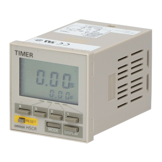
Multifunction Digital Timer
1/16 DIN Timer with Easy-to-use
Functions
I
Nine output modes accommodate a wide variety
of applications.
I
All parameters set by scroll-through menus
accessed from the front panel.
I
Field-selectable time ranges from 0.001 second to
9999 hours.
I
High visibility LCD display with built-in backlight.
I
Precision control possible to 0.001 second.
I
Four levels of key protection provided.
I
Selectable elapsed time (UP) and remaining time
(DOWN) display.
I
Model H5CR-S only 64 mm deep.
I
Conforms to EMC standards.
I
Six-language instruction manual provided.
Ordering Information
Functions
Contact type
Unit Depth
Basic (78 mm)
Display
Backlit
---
Not backlit
H5CR-L
Supply
AC
24/100 to 240 V,
voltages
50/60 Hz
DC
12 to 24 V
Note:
Add the supply voltage to the part number when ordering.
Model Legend
I
Note:
Models with a finger safe terminal cover can be ordered by adding "-500" to the end of the model number. (Except for H5CR-L
e.g., H5CR-B-500 (100 to 240 VDC, 50/60 Hz)
The finger safe terminal cover provides finger protection conforming to VDE0106/P100.
SPDT relay
Standard
Short body
(100 mm)
H5CR-B
H5CR-S
---
---
24/100 to 240 V,
---
50/60 Hz
---
12 to 24 V
H5CR -
2. Output type classifier
Blank: Relay output
S:
1. Type classifier
L: Basic
B: Standard
S: Short body
9 field selectable
Solid-state open collector
Basic (78 mm)
(64 mm)
---
H5CR-LS
24/100 to 240 V,
50/60 Hz
12 to 24 V
Solid-state output
H5CR
RC+
Standard
Short body
(100 mm)
(64 mm)
H5CR-BS
H5CR-SS
---
---
24/100 to 240 V,
---
50/60 Hz
---
12 to 24 V
#
)
1
Advertisement
Table of Contents

Related Manuals for Omron H5CR


Summary of Contents for Omron H5CR
- Page 1 S: Short body Note: Models with a finger safe terminal cover can be ordered by adding “-500” to the end of the model number. (Except for H5CR-L e.g., H5CR-B-500 (100 to 240 VDC, 50/60 Hz) The finger safe terminal cover provides finger protection conforming to VDE0106/P100.
-
Page 2: Specifications
Back Connecting Socket (for H5CR-L only) P3G-08 Finger safe type P3G-08 with Y92A-48G (see note 1) Finger Safe Terminal Cover for H5CR-B Y92A-48T Flush Mounting Adapter (see note 2) Y92F-30 Note: 1. Y92A-48G is a finger safe terminal cover which is attached to the P3G-08 Socket. - Page 3 10 V/m (80 MHz to 1 GHz) (level 3) Immunity Conducted Disturbance: ENV50141: 10 V (0.15 to 80 MHz) (level 3) Immunity Burst: EN61000-4-4: 2 kV power-line (level 3) 2 kV I/O signal-line (level 4) Weight H5CR-L: Approx. 105 g, H5CR-B: Approx. 160 g, H5CR-S: Approx. 120 g...
-
Page 4: Operation Key
Used to change 3. Reset indicator data in the set mode.) 4. Gate indicator (not included in the H5CR-L) 12. Display key 5. Key protection indicator (Switches to the present value display.) (not included in the H5CR-L) 6. -
Page 5: Operation
Power outage Battery detector AC (DC) input Power circuits * DC input only for H5CR-S * Power supply is not insulated from I/O. I/O Functions Inputs Start signal Stops timing in A-2 and A-3 (power on delay) modes. Starts timing in other modes. - Page 6 H5CR H5CR Operational Overview This flowchart shows operation common to all H5CR models. Refer to the following Setting Item Table for details on the operation of specific models. Run mode Setting mode Press the MODE key Present value, set value...
- Page 7 <KP-4> H5CR-B H5CR-B Note: 1. Changes made in setting mode become effective when run mode is entered. 2. The time range setting appears first when setting mode is entered. 3. *The key protection function is not included in the H5CR-L.
-
Page 8: Run Mode
H5CR H5CR Examples Run Mode Changing the Set Value To change the set value from 3 hr 5 min to 4 hr 5 min, press the 3 key so that the number 4 appears in the hour’s place. • Pressing keys 1 through 4 increments the corresponding col- umn by 1. - Page 9 H5CR H5CR Timing Charts The gate input is not included in the H5CR-L. One-shot Sustained output One-shot outputs can be set to 0.1 s, 0.5 s, 1 s, 5 s, 10 s, 20 s. Output mode A: Signal ON delay 1 (Timer resets when power comes ON.)
- Page 10 H5CR H5CR Output mode b: Repeat cycle 1 (Timer resets when power comes ON.) Timing starts when the start signal goes ON. Sustained Output The status of the control output is reversed when time Power is up (OFF at start).
- Page 11 H5CR H5CR Output mode d: Signal OFF delay (Timer resets when power comes ON.) The control output is ON when the start signal is ON (except when the power is OFF or the reset is Power ON). The timer is reset when the time is up.
- Page 12 H5CR H5CR Dimensions Note: All units are in millimeters unless otherwise indicated. H5CR-L Surface/Flush Mounting 84.0 14.3 63.7 44.8 x 44.8 H5CR-B Flush Mounting 44.8 x 44.8 H5CR-S Flush Mounting 44.8 x 44.8...
- Page 13 H5CR H5CR Dimensions with Y92F-30 Flush Mounting Adapter H5CR-L Surface Mounting Y92F-30 P3G-08 Flush mounting Panel Rear surface adapter connection socket H5CR-L 92.8 P2CF-08 85.9 H5CR-B Y92F-30 Panel Flush mounting adapter 44.8 x 44.8 Panel Cutouts H5CR-S Panel cutouts are as shown below.
- Page 14 Internal Connections P3G-08 (Bottom View) Finger Safe Terminal Cover Conforming to VDE0106/P100 Y92A-48G Twelve, 6.4 dia. holes (Attachment for P3G-08 Socket) 48 x 48 47.7 x 47.7 16.5 24.6 27.6 Y92A-48T 47.4 (Attachment for H5CR-B Soft Cover Hard Cover Y92A-48F1 Y92A-48...
-
Page 15: Installation
12 to 24 VDC 100 to 240 VAC/24 VAC 12 to 24 VDC Note: Do not connect unused terminals. Connections The inputs of the H5CR are no-voltage (short circuit or open) inputs. No-contact Input Contact Input No-contact Input (NPN Transistor) (30 V max.) - Page 16 H5CR H5CR Precautions Power Supplies Changing Set Values • The input circuit is not insulated from the power supply circuit. • The Timer set value can be changed while the timer is operating, The internal circuit might be damaged by a surrounding AC cir-...
Need help?
Do you have a question about the H5CR and is the answer not in the manual?
Questions and answers