Table of Contents
Advertisement
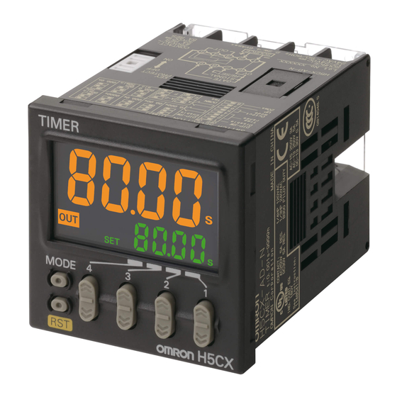
Digital Timer
H5CX
Please read and understand this catalog before purchasing the products. Please consult your OMRON representative if you have any questions
or comments. Refer to Warranty and Application Considerations (page 52), and Safety Precautions (page 47).
DIN 48 ´ 48-mm Multifunction Digital Timer/2-stage Digital Timer
• Highly visible display with backlit negative transmissive LCD.
• Finger-safe terminals (screw terminal block models).
• Complies with IP66, NEMA4, and UL Type 4X (when using the Y92S-29 Waterproof Packing and Y92F-30 Flush Mounting Adapt-
er).
H5CX-A/-L
Multifunction Digital Timer
with 4-digit display
H5CX-A (standard type)
H5CX-L (economy type)
H5CX Series
Contents
Multifunction Digital Timer
H5CX-A/-L........................................................
2-stage Digital Timer
H5CX-B............................................................ 35
Common to All Models
Safety Precautions ........................................... 47
Warranty and Application Considerations ........ 52
H5CX-B
1
2
2-stage Digital Timer
with 6-digit display
H5CX-B
2
H5CX
Digital Timer
1
Advertisement
Chapters
Table of Contents

Subscribe to Our Youtube Channel
Related Manuals for Omron H5CX


Summary of Contents for Omron H5CX
- Page 1 Digital Timer H5CX Please read and understand this catalog before purchasing the products. Please consult your OMRON representative if you have any questions or comments. Refer to Warranty and Application Considerations (page 52), and Safety Precautions (page 47). DIN 48 ´ 48-mm Multifunction Digital Timer/2-stage Digital Timer •...
-
Page 2: Table Of Contents
(screw terminal block models). • Intuitive setting enabled using DIP switch (H5CX-A/-A11 mod- els) and ergonomic up/down digit keys. • Twin timer in one body to meet a broader range of cyclic control application requirements as well as ON/OFF duty adjustable flicker mode. -
Page 3: Model Number Structure
H5CX-L8SD Note: Depending on the wiring, unwanted current from the AC power supply may occasionally burn out internal parts. H5CX-A/-L (except for H5CX-A11/-A11S) models do not have a transformer. Therefore, the power supply and input circuit are not insulated. Refer to Safety Pre- cautions (H5CX-A/-L) on page 49 for wiring details. -
Page 4: Specifications
EEPROM (overwrites: 100,000 times min.) that can store data for 10 years min. Operating: - 10 to 55 ° C ( - 10 to 50 ° C if timers are mounted side by side) (with no icing or condensation) Ambient temperature - 25 to 65 °... - Page 5 Signal start for transistor output model: ± 0.005% ± 3 ms max. (See note 2.) fluences) (See note 1.) If the set value is within the sensor waiting time at startup the control output of the H5CX will not turn ON until the sensor waiting time passes.
- Page 6 A maximum current of 0.15 A can be switched at 125 VDC (cos f =1) and a maximum current of 0.1 A can be switched if L/R is 7 ms. In both cases, a life of 100,000 operations can be expected. The minimum applicable load is 10 mA at 5 VDC (failure level: P).
-
Page 7: Connections
Internal control Input circuit circuit Key switch circuit Note: Power circuit is not insulated from the input circuit, except for H5CX-A11/-A11S, which have basic insulation. I/O Functions Inputs Start signal Stops timing in A-2 and A-3 (power ON delay) modes. - Page 8 Note 1. Do not connect unused terminals as relay terminals. 2. The power supply and input circuit are not insulated, so unwanted current from the AC power supply may burn out internal parts. Refer to Safety Precautions (H5CX-A/-L) on page 49 for wiring details.
- Page 9 The inputs of the H5CX-A@/-A11@ are no-voltage (short-circuit or open) inputs or voltage inputs. The input of the H5CX-L8@ is no-voltage input only. Note: Power circuit is not insulated from the input circuit, except for H5CX-A11/-A11S, which have basic insulation. For wiring, refer to Safety Pre- cautions (H5CX-A/-L) on page 49.
- Page 10 Operate with transistor OFF Voltage Input Signal Levels High level (Input ON): 4.5 to 30 VDC Low level (Input OFF): 0 to 2 VDC Approx. 4.7 k W Input resistance: Note: The DC voltage must be 30 VDC max. H5CX-A/-L Multifunction Digital Timer...
-
Page 11: Nomenclature
Front View Time Unit Display Switches (Color is same as present value.): (If the time range is 0 min, 0 h, 0.0 h, Key-protect Switch or 0 h 0 min, this display flashes to indicate timing operation.) (Default setting) OFF... -
Page 12: Dimensions
Dimensions Note: All units are in millimeters unless otherwise indicated. Dimensions without Flush Mounting Adapter H5CX-A/-AS (Flush Mounting Models) 48x48 44.8x44.8 Note: M3.5 terminal screw (effective length: 6 mm) H5CX-AD/-ASD (Flush Mounting Models) 48x48 44.8x44.8 Note: M3.5 terminal screw (effective length: 6 mm) H5CX-A11/-A11S (Flush Mounting/Surface Mounting Models) 14.4... - Page 13 Adapters are mounted so that the gap between 98.7 sides with hooks is at least 15 mm. 3. It is possible to mount timers side H5CX-A11D/-A11SD (Adapter and Waterproof Packing Ordered Separately) by side, but only in the direction without the hooks.
- Page 14 100.9 103.2 92.3 P2CF-08-@ P2CF-11-@ P2CF-11-@ Note: These dimensions vary with the kind of DIN track (reference value). Accessories (Order Separately) Note: All units are in millimeters unless otherwise indicated. Track Mounting/Front Connecting Socket Eight, P2CF-08 M3.5 x 7.5 sems 70 max.
- Page 15 Terminal Arrangement/ 70 max. 35.4 Internal Connections (Top View) Surface Mounting Holes Two, 4.5 dia. holes Two, 4.5 dia. or two, M4 50 max. 31.2 max. 40±0.2 P2CF-11-E (Finger Safe Terminal Type) Conforming to VDE0106/P100 Eleven, M3.5 x 7.5 sems 70 max.
- Page 16 (provided with H5CX-A@ models) Y92F-30 Y92S-29 Note: Order the Flush Mounting Adapter separately if it is lost or dam- Note: Use Waterproof Packing to provide a level of water protection aged. that complies with NEMA4, UL Type 4X, or IP66 standards. Or- der the Waterproof Packing separately if it is lost or damaged.
-
Page 17: Operating Procedures
For details on the setting methods, refer to page 19. Note: At the time of delivery, the H5CX is set for timer operation. Settings for Twin Timer Operation Use the following settings for all models except the H5CX-L8@. -
Page 18: Operating Procedures (Timer Function)
Note 1. Be sure to set pin 1 of the DIP switch to ON. If it is set to OFF, the DIP switch settings will not be enabled. 2. Changes to DIP switch settings are enabled when the power is turned ON. (Perform DIP switch settings while the power is OFF.) 3. - Page 19 Settings for Advanced Functions Settings that cannot be performed with the DIP switch are performed with the operation keys. Power ON For details on operations in run mode, refer to page 21. Note 1. If the mode is switched to the function setting mode during operation, operation will continue.
- Page 20 Set the key protect level. When the key-protect switch is set to ON, it is possible to prevent setting errors by prohibiting the use of certain operation keys by specifying the key protect level (KP-1 to KP-5). The key protect indicator is lit while the key-protect switch is set to ON.
- Page 21 ON duty 0%↔100% Examples: 1. If the cycle time is 20 s, the ON duty ratio is 31%, and the time range is 1 s to 9999 s, the ON time is given by the following: 31 (%) 20 (s) ´...
- Page 22 Timing diagram Set value DOWN Output mode A-3: Power ON delay 2 (Timer does not reset when power comes ON.) Timing starts when the reset input goes OFF. Power The start signal disables the timing function (i.e., same function as the gate input).
- Page 23 Set the value to at least 100 ms (contact output type). DOWN Start signal input is disabled during timing. Output mode b-1: Repeat cycle 2 (Timer does not reset when power comes ON.) Sustained Timing starts when the start signal goes ON. Power...
- Page 24 The set value shows the ON duty (%) and can be set to a value between 0 and 100 (%). When the cycle time is 0, the output will always be OFF. When the cycle time is not 0 and when ON duty has been set to 0 (%), the output will always be OFF. When ON duty has been set to 100 (%), the output will always be ON.
- Page 25 Memory error (RAM) Reset the power supply. No change Memory error (EEP) Reset to the factory settings using (See note) the reset key. Note: This includes times when the life of the EEPROM has expired. H5CX-A/-L (Timer Function) Multifunction Digital Timer...
-
Page 26: Operating Procedures (Twin Timer Function)
For details, refer to page 31. Note 1. Be sure to set pin 1 of the DIP switch to ON. If it is set to OFF, the DIP switch settings will not be enabled. 2. Changes to DIP switch settings are enabled when the power is turned ON. (Perform DIP switch settings while the power is OFF.) 3. - Page 27 Power ON For details on operations in run mode, refer to page 29. Note 1. If the mode is switched to the function setting mode during operation, operation will continue. 2. Changes made to settings in function setting mode are enabled for the first time when the mode is changed to run mode.
- Page 28 Set the key protect level. When the key-protect switch is set to ON, it is possible to prevent setting errors by prohibiting the use of certain operation keys by specifying the key protect level (KP-1 to KP-5). The key protect indicator is lit while the key-protect switch is set to ON.
- Page 29 ON set time Present Value and OFF Set Time The present value is displayed in the main display and the OFF set time is displayed in the sub-display. “SET1” lights at the same time. Present Value and ON Set Time The present value is displayed in the main display and the ON set time is displayed in the sub-display.
- Page 30 Memory error (RAM) Reset the power supply. No change Memory error (EEP) Reset to the factory settings using (See note) the reset key. Note: This includes times when the life of the EEPROM has expired. H5CX-A/-L (Twin Timer Function) Multifunction Digital Timer...
-
Page 31: Operation In Timer/Twin Timer Selection Mode
Operation in Timer/Twin Timer Selection Mode Select whether the H5CX is used as a timer or a twin timer in timer/twin timer selection mode. The H5CX is also equipped with a DIP switch monitor function, a convenient function that enables the settings of the DIP switch pins to be confirmed using the front display. -
Page 32: Additional Information
Key protect level Note 1. All setting changes are performed using the keys. 2. The above flowcharts outline the procedure for all models. For details on specific models, refer to page 19 (timer operation) or page 27 (twin timer operation). H5CX-A/-L... - Page 33 List of Settings Fill in your set values in the set value column of the following tables and utilize the tables for quick reference. Timer/Twin Timer Selection Mode Parameter Parameter Setting range Default value Unit Set value name func tim/twin...
- Page 34 Run Mode Parameter name Parameter Setting range Default value Unit Set value 0.00 to 99.99 (Time range: --,--s) 0.00 Present value, OFF set time OFF set time 0.0 to 999.9 (Time range: ---,-s) 0 to 9999 (Time range: ----s) 0:00 to 99:59 (Time range: --min--s) 0:00 min;...
-
Page 35: H5Cx-B
DIN 48 ´ 48-mm Digital Timer with 6-digit Display and Forecast Output • Times the daily operating hours of machinery and tools, predict- ing and notifying when maintenance is required. • The 2-stage settings and forecast output are ideal for mainte- nance applications. -
Page 36: Model Number Structure
Output type Supply voltage 6-digit display Screw terminals Transistor 12 to 24 VDC H5CX-BWSD Accessories (Order Separately) Name Models Flush Mounting Adapter (See note.) Y92F-30 Waterproof Packing (See note.) Y92S-29 Hard Cover Y92A-48 Soft Cover Y92A-48F1 Note: Supplied with H5CX-BWSD. H5CX-B... -
Page 37: Specifications
EEPROM (overwrites: 100,000 times min.) that can store data for 10 years min. Operating: - 10 to 55 ° C ( - 10 to 50 ° C if timers are mounted side by side) (with no icing or condensation) Ambient temperature - 25 to 65 °... - Page 38 Signal start (minimum pulse width of 1 ms): ± 0.01% ± 3 ms max. fluences) (See note 1.) If the set value is within the sensor waiting time at startup the control output of the H5CX will not turn ON until the sensor waiting time passes.
-
Page 39: Connections
Start signal Starts timing. Reset Resets present value. (The present value returns to 0.) Timing stops and control output turns OFF while reset input is ON. Reset indicator is lit while reset input is ON. Gate Inhibits timer operation. Outputs... - Page 40 3. Terminals 1 and 6 are connected internally. 4. Terminals 7 and 10 have the same reset function. The same function will be performed whichever terminal is connected. Terminals 7 and 10 are not connected internally, however, so do not use them for cross-over wiring.
- Page 41 Input Connections The inputs of the H5CX-B are no-voltage (short-circuit or open) inputs or voltage inputs. No-voltage Inputs (NPN Inputs) Contact Input Open Collector Voltage Output DC Two-wire Sensor PLC or sensor Sensor Operate with transistor ON Operate with relay ON...
-
Page 42: Nomenclature
DIP switch. (Default setting) Unit Label The unit label is included with the Unit. Affix the unit label in the posi- tion shown in the following diagram to match the time range to be used. Align the right edge of the label with the right edge of the display window. -
Page 43: Dimensions
(provided with H5CX-BWSD) Y92F-30 Y92S-29 Note: Order the Flush Mounting Adapter separately if it is lost or dam- Note: Use Waterproof Packing to provide a level of water protection that complies with NEMA4, UL Type 4X, or IP66 standards. Or- aged. -
Page 44: Operating Procedures
The forecast value = set value - forecast set value Turn ON the power again. The forecast set value is used to set the deviation for the set value. • OUT2 (control output) turns ON when the present value reaches the set value. - Page 45 0.1 h to 99999.9 h 0.01 s to 9999.99 s Output mode F-1 mode A mode 0 h 00 min 01 s to 99 h 59 min 59 s Input signal width 20 ms 1 ms 0.1 min to 99999.9 min...
- Page 46 Output is instantaneous when the set value is 0. Note: Forecast Value = Set Value - Forecast Set Value The forecast set value is used to set the deviation for the set value. Self-diagnostic Function The following displays will appear if an error occurs.
-
Page 47: Safety Precautions
• Store at the specified temperature. If the H5CX has been stored at a temperature of less than –10 ° C, allow the H5CX to stand at room temperature for at least 3 hours before use. - Page 48 ON, the time display will actually start from 250 ms. If the set (except for H5CX-A11/-A11S). value is 249 ms or less, the time until output turns ON will be a fixed value between 200 and 250. (Normal operation is possible for set Basic insulation between power supply and output terminals, and value of 250 ms or more.) In applications where a set value of...
- Page 49 When changing the set value during a timing operation, the output use. will turn ON if the set value is changed as follows because of the use of a constant read-in system: For the power supply of an input device of the H5CX (except for Elapsed time (UP) mode: Present value ³...
- Page 50 Precautions for Safe Use Changing the Set Value When changing the set value during a timing operation, the output will turn ON if the set value is changed as follows because of the use of a constant read-in system: Forecast Value Setting When the present value ³...
- Page 51 H5CX Digital Timer...
-
Page 52: Warranty And Application Considerations
CONTRACT, WARRANTY, NEGLIGENCE, OR STRICT LIABILITY. In no event shall the responsibility of OMRON for any act exceed the individual price of the product on which liability is asserted. IN NO EVENT SHALL OMRON BE RESPONSIBLE FOR WARRANTY, REPAIR, OR OTHER CLAIMS REGARDING THE...
Need help?
Do you have a question about the H5CX and is the answer not in the manual?
Questions and answers