Table of Contents
Advertisement
Quick Links
Advertisement
Table of Contents

Related Manuals for Keysight Technologies Agilent Technologies PXI Express M9202A


Summary of Contents for Keysight Technologies Agilent Technologies PXI Express M9202A
- Page 1 Agilent Technologies PXI Express 12-bit Wideband IF Digitizer M9202A Startup Guide NOTICE: This document contains references to Agilent Technologies. Agilent’s former Test and Measurement business has become Keysight Technologies. For more information, go to www.keysight.com.
- Page 2 shall not be liable for errors or for incidental Notices or consequential damages in connection with If this product is not used as specified, the the furnishing, use, or performance of this © 2011-2012 Agilent Technologies, Inc. protection provided by the equipment could document or of any information No part of this manual may be reproduced in be impaired.
- Page 3 associated with local AC mains connections. from the entire test system and discharge beyond a WARNING notice until the Assume all measurement, control, and data any capacitors before: connecting or discon- indicated conditions are fully understood I/O connections are for connection to necting cables or jumpers, installing or and met.
- Page 4 expected to leak or deteriorate during Front and Rear Panel Symbols: normal use. Forty years is the expected useful life of the product. The CE mark is a registered trademark of the European This symbol indicates the Community. instrument is sensitive to electro- static discharge (ESD).
-
Page 5: Table Of Contents
Table of Contents Documentation Map Agilent M9202A Introduction Related Documentation Follow the Startup Sequence Step 1: Unpack and Inspect the Module Inspect for damage Return the module for service Step 2: Verify the M9202A Shipment Contents Step 3: Install the Software Step 4: Install the Module M9202A Front Panel Features Front Panel Connectors... -
Page 6: Documentation Map
Documentation Map M9202A PXI Express 12-bit Wideband IF Digitizer Startup Guide... -
Page 7: Agilent M9202A Introduction
Related Documentation Agilent M9202A Introduction The scope of this Startup Guide is to detail the processes of receiving and installing the Agilent M9202A PXI Express 12-bit Wideband IF Digitizer, installing the required software, and verifying basic module operation. If you have any questions after reviewing this information, please contact your local Agilent representative or contact us through our website at www.agilent.com/find/assist Related Documentation... -
Page 8: Step 1: Unpack And Inspect The Module
Inspect for damage Step 1: Unpack and Inspect the Module The module is shipped in materials which prevent damage from static. The module should only be removed from the packaging in an anti-static area ensuring that correct anti-static precautions are taken. -
Page 9: Step 2: Verify The M9202A Shipment Contents
Return the module for service Product model number (for example, M9202A). Product serial number (for example, USxxxxxxxx). The serial number label is located on the side panel of the module. The serial number can also be read from the Soft Front Panel interface, but only after the software is installed Description of failure or service required 4. -
Page 10: Step 3: Install The Software
Return the module for service Step 3: Install the Software System Requirements Item Requirements Windows Vista® SP1 and SP2, Linux Operating sys- kernel 2.6 or higher (32 or 64-bit), Windows XP SP3 Windows 7® (32 or 64-bit), All versions. Debian 6.0, CentOS 5 Processor 600 MHz or higher required 1 GHz 32-bit (x86), 1 GHz 64-bit... - Page 11 Return the module for service Install the Software The M9202A PXI Express 12-bit Wideband IF Digitizer module software is located on the Agilent MD1 High- Speed Digitizer Software and Product Information CD CD (M9210-90007) and the Agilent IO Library Suite CD (E2904-60003).
-
Page 12: Step 4: Install The Module
Return the module for service Step 4: Install the Module PXI hardware does not support "hot-swap" operation. Before installing the module into the chassis, power off the chassis to prevent damage to the module. The module can be installed in any PXIe slot marked with a peripheral slot compatibility image (a circle containing the slot number). -
Page 13: M9202A Front Panel Features
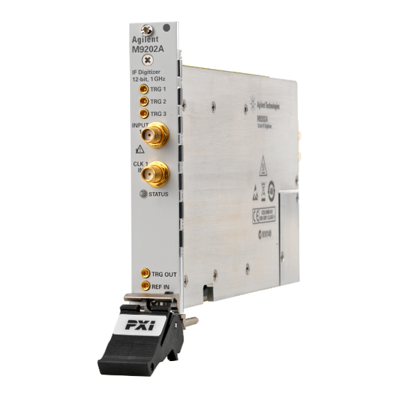
M9202A Front Panel Features M9202A Front Panel Features Front Panel Connectors Connector Description This MMCX female connector is a 50 Ω terminated input for an external trigger sig- TRG 1 nal. The trigger signal range is ± 5 V This MMCX female connector is a 50 Ω terminated input for an external trigger sig- TRG 2 nal. -
Page 14: Step 5: Verify Operation Of The M9202A Module
M9202A Front Panel Features Step 5: Verify Operation of the M9202A Module The intention of this step is to verify correct operation of the newly installed module. 1. Run Agilent Connection Expert (from the desktop icon, or from Start > Programs > Agilent IO Libraries Suite >... -
Page 15: Conducting A Self-Test
Conducting a Self-Test Conducting a Self-Test The purpose of this self-test is to verify that the unit functions correctly, in that it can self-calibrate and communicate with the processor controlling it. When the SFP is launched it will initiate a self-calibration which takes a little over 1 minute. Verify that no error is shown in the lower left hand log area. -
Page 16: Conduct M9202A Operational Check (Optional)
Conduct M9202A Operational check (optional) Conduct M9202A Operational check (optional) Requirements for Verification The M9202A is verified by using it to trigger on and visualize a signal from a Function Generator. The trigger must be stable and the signal frequency and amplitude must correspond to that set on the generator. Required Hardware To verify that the module works requires an external signal source which will be sent to both the input and the trigger. -
Page 17: If A Problem Is Found
Conduct M9202A Operational check (optional) Figure 6 - SFP showing measured waveform If a Problem is Found 1. Verify that you have set all configuration settings as shown above. 2. Verify that the RF Generator is ON and producing the desired signals at the end of the BNC cables. This can be done with an oscilloscope. - Page 18 The Modular Tangram www.agilent.com www.agilent.com/find/modular The four-sided geometric symbol that appears in Agilent modular product literature is called a tangram. The goal of this seven-piece www.agilent.com/find/digitizers puzzle is to create shapes—from simple to complex. As with a tangram, the possibilities may seem infinite as you begin to create For more information on Agilent Technologies' products, a new test system.