Table of Contents
Advertisement
Quick Links
DO
GUIDE
AMP-150-70/AMP-150-100/AMP-225/AMP-1200-70/AMP-1200-100/
AMP-2100/AMP-2100-70/AMP-2100-100
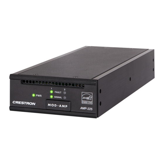
Modular Amplifiers
The Crestron
®
Modular Amplifier Series can be configured for individual module use on a flat surface or
ganged together (one or more modules) with the "slide-lock" system for installation in a 1U rack space.
The amplifiers are functionally similar to each other with varying capabilities. For simplicity within this
guide, the term "amplifier" is used except where noted.
DO
Assemble the Device
If a single amplifier is to be used on a flat surface, refer to "Placing onto a Flat Surface." Otherwise,
continue below for instructions on creating an amplifier assembly that can be placed in a standard
equipment rack. The only tools needed are a #1 or # 2 Phillips screwdriver, and a 1/4" nut driver.
Gang Amplifiers Together
Perform the following procedure to gang amplifiers together. Refer to the diagrams.
1. Remove the two screws securing rail 1 to the amplifier (unit 1).
Unit 1
Rail 1
Remove these
screws.
2. Remove rail 1 from unit 1 by sliding it off the side of the amplifier.
Rail 1
Unit 1
3. Attach rail 1 to unit 2 using the three included Phillips-head screws. Make sure that the screw holes
on the underside of rail 1 are on the bottom.
Rail 1
Unit 2
Rail 2
NOTE:
Do not remove rail 2.
DO
Check the Box
QUANTITY
4. Slide unit 1 into unit 2 assembly.
Unit 2 assembly
Unit 1
5. Secure unit 1 to unit 2 assembly with the two screws removed in step 1.
Unit 1
Unit 2 assembly
6. Repeat steps 1 through 5 for additional amplifiers.
Configure for Rack Installation
Before an amplifier can be installed in a rack, additional hardware must be installed.
Faceplates
If an amplifier or group of amplifiers is not wide enough to mount in a rack, faceplates can be assembled
to "widen" the amplifier to fit. Create a faceplate by attaching an extrusion plate to a quarter-width or
half-width rack ear, as shown in the following diagrams. Secure the extrusion plate to the rack ear using
a 1/4" nut driver and the included nuts.
Quarter-size faceplate bracket
Half-size faceplate bracket
PRODUCT
1
Attenuator Cover, Magnetic, Security
2
Bracket, Wall Mount
1
Connector, 5-Pin
1
Extrusion Plate, Half-Width
1
Extrusion Plate, Quarter-Width
4
Foot, 0.5" x 0.5" x 0.23", Adhesive
1
Half-Width Rack Ear, 1U
4
Nut, 04-40, Keps
1
Power Cord, 6' 7" (2 m)
1
Quarter-Width Rack Ear, 1U
6
Screw, 6-32 x 3/8", Undercut Head, Phillips
AMP-150-70, AMP-150-100, AMP-1200-70, AMP-1200-100 Only
1
Connector, 2-Pin
AMP-225, AMP-2100, AMP-2100-70, AMP-2100-100 Only
2
Connector, 2-Pin
Attach Rack Ears to Amplifiers
Attach the faceplate bracket(s) or rack ears, as required, to the amplifier(s). Refer to the following
diagram for details.
Quarter-size rack ear
(no faceplate attached)
NOTE:
Faceplates should not be attached to rack ears that are attached to the length of the amplifier.
DO
Install the Device
Once assembled, the amplifier can be mounted into a rack, mounted onto a flat surface, or placed onto
a flat surface.
Mounting into a Rack
Each amplifier occupies 1U of rack space. Using a #1 or #2 Phillips screwdriver, mount the device into
the rack using four mounting screws (not included).
Mounting onto a Flat Surface
1. Install the wall mount brackets with three Phillips-head screws (included) per side.
2. Secure the amplifier to a flat surface using four mounting screws (not included).
COLOR
PART NUMBER
4525789
2046992
2003577
4525245
4525244
Black
2002389
2046652
2004878
2001134
2046651
Black
2007235
2044402
2044402
Half-size faceplate bracket
Advertisement
Table of Contents

Related Manuals for Crestron AMP-1200-100


Summary of Contents for Crestron AMP-1200-100
- Page 1 AMP-150-70, AMP-150-100, AMP-1200-70, AMP-1200-100 Only equipment rack. The only tools needed are a #1 or # 2 Phillips screwdriver, and a 1/4" nut driver.
- Page 2 Crestron and the Crestron logo are either trademarks or registered trademarks of Crestron Electronics, Inc., in the United States and/or other countries. UL and the UL logo are either trademarks or registered trademarks of Underwriters Laboratories, Inc. in the United States and/or other countries.
Need help?
Do you have a question about the AMP-1200-100 and is the answer not in the manual?
Questions and answers