
Related Manuals for Inficon Pernicka 700H CHLD


Summary of Contents for Inficon Pernicka 700H CHLD
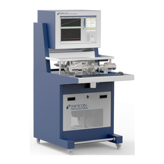
- Page 1 Translation of the original operating instructions Pernicka 700H CHLD Leak detector Catalog No. 550-700, 550-701 From software version jin76aen1-04-(1911) 7.01.04...
- Page 2 INFICON GmbH Bonner Strasse 498 50968 Cologne, Germany...
-
Page 3: Table Of Contents
INFICON Table of Contents Table of Contents 1 About these instructions ........................... 7 1.1 Target groups ............................ 7 1.2 Other associated documents ........................ 7 1.3 Warnings.............................. 7 1.4 Definition of terms............................. 8 2 Safety ................................ 10 2.1 Intended use ............................ 10 2.2 Owner requirements .......................... 10 2.3 Duties of the operator .......................... 11 2.4 Dangers .............................. 12... - Page 4 Table of Contents INFICON 4.3.6.2 Electrical data........................ 26 4.3.6.3 Physical data........................ 26 4.3.6.4 Ambient conditions...................... 27 5 Installation .............................. 28 5.1 Prerequisites for the installation...................... 28 5.2 Setup .............................. 29 5.3 Connecting the compressor........................ 31 5.4 Connecting the compressed air ...................... 34 5.5 Connecting the purge gas........................ 35 5.6 Connect the device to the mains power.................... 36 5.7 Connecting the device to an exhaust system (optional) ................. 37...
- Page 5 INFICON Table of Contents 6.5.3.1 Select the "Mini" window and start the measurement ............ 62 6.5.3.2 Select the "Measure" window and start the measurement.......... 63 6.5.3.3 Perform gross leak test ...................... 64 6.5.3.4 Terminate the measurement process after gross leak test .......... 64 6.5.3.5 Carry out a fine leak test .................... 65...
- Page 6 Table of Contents INFICON 9 Decommissioning the device.......................... 88 9.1 Deinstallation ............................ 88 9.1.1 Disconnect the device from the power supply ................ 88 9.1.2 Separate the purge gas ...................... 89 9.1.3 Separate the compressed air...................... 90 9.1.4 Disconnect the compressor ...................... 90 9.2 Sending in the device .......................... 92...
-
Page 7: About These Instructions
INFICON About these instructions | 1 1 About these instructions This document applies to the software version stated on the title page. Product names may occur in the document, which are added for identification purposes only and belong to the respective owner of the rights. -
Page 8: Definition Of Terms
1 | About these instructions INFICON NOTICE Hazardous situation resulting in damage to property or the environment 1.4 Definition of terms Use of gas types in the device The device is a helium leak detector. If you want to use a forming gas instead of helium to detect the hydrogen contained therein, the information for helium also applies to hydrogen. - Page 9 INFICON About these instructions | 1 Accumulation Accumulation is a phase during the measuring procedure. Tracer gas escaping from the test object is accumulated in the closed measuring system. The change in the tracer gas quantity over time serves to determine the leak rate.
-
Page 10: Safety
2 | Safety INFICON 2 Safety 2.1 Intended use The Pernicka 700H CHLD (Cumulative Helium Leak Detector) is a cumulative helium leak detector for measuring very small leak rates. Improper use Avoid the following, non-intended uses: • Place the unit so that power switches / connections for power supply are not easily accessible •... -
Page 11: Duties Of The Operator
INFICON Safety | 2 Personnel qualifications • Only instructed personnel should be permitted to work with and on the device. The instructed personnel must have received training on the device. • Make sure that authorized personnel have read and understood the operating instructions and all other applicable documents. -
Page 12: Dangers
2 | Safety INFICON 2.4 Dangers The measuring instrument was built according to the state-of-the-art and the recognized safety regulations. Nevertheless, improper use may result in risk to life and limb on the part of the user or third parties, or damage to the measuring instrument or other property may occur. -
Page 13: Shipment, Transport, Storage
Spiral cable for wrist band Allen wrench, modified 9/64 inch PE bags 100 mm x 150 mm x 0.05 mm PE bags 180 mm x 250 mm x 0.05 mm Transport box for Pernicka 700H CHLD Tilt sensor Shock sensor Double label 110 x 60 mm Original instruction manual Supplier documentation (see Chapter "Other applicable... -
Page 14: Unpacking The Device And Compressor
The unit and the cryogenic pump compressor can be damaged during transport. The delivery consists of a box with the Pernicka 700H CHLD and a cardboard box with the cryogenic pump compressor. The transport box is secured with tilt and shock sensors. -
Page 15: Unpack The Device
Remove the packing material from the transport box. Remove the carton from the transport box. Open the carton, remove the packaging material and remove the components. Transport strap Cross beams Pernicka 700H CHLD Wedge with loop Pernicka-700H-CHLD-Operating-instructions-jin76aen1-04-(1911) 15 / 100... - Page 16 3 | Shipment, Transport, Storage INFICON Loosen the 2 transport straps. To loosen the 2 wedges, pull on the loops. Remove the cross beam from the transport box. Place the 2 wedges in front of the transport box on the floor.
-
Page 17: Unpack The Compressor
INFICON Shipment, Transport, Storage | 3 3.1.2 Unpack the compressor CAUTION Danger of injury when lifting the heavy cryogenic pump compressor The cryogenic pump compressor weighs approx. 68 kg and can slip out of your hands. ► Lift and transport the cryogenic pump compressor only with two people. -
Page 18: Description
4 | Description INFICON 4 Description 4.1 Function The device is a leak detector for detecting and measuring leaks in sealed test objects. Description of the measurement process The device is in the "Standby" operating mode at the start of the measurement process. -
Page 19: Operation Modes
INFICON Description | 4 helium signal falls below this setpoint, the helium is removed from the system with the turbo molecular pump and then the measurement process is continued with the fine leak test. In the fine leak test, the gases escaping from the test object, except for helium, are pumped out with the cryogenic pump. -
Page 20: Construction
4 | Description INFICON 4.3 Construction 4.3.1 Device and compressor Device Display with measurement program Storage Interfaces Test chamber for test object Valve Valve groups groups Device Trackball Connection for Keyboard customer calibration leak (optional) Cryogenic pump compressor Selector switch for main frequency... -
Page 21: Control Unit
INFICON Description | 4 Device PID-regulator WATLOW Display -Temperature measurement device cryogenic pump heater for cryogenic pump Mass spectrometer CHLD-Sensor Valve for turbo molecular Calibration leak pump Purge gas connection Turbo molecular pump (hidden) Mains switch Power supply Compressed air... -
Page 22: Display
4 | Description INFICON For the insertion of a USB bar code reader for the automatic detection of information of the test objects to be measured. For the insertion of a USB flash drive with Update information or for connecting a USB printer to print out test results. -
Page 23: Vacuum Connections
INFICON Description | 4 System diagram Displays the current states of the individual components of the device during a measurement process. Selection menu To select modes with expanded functionality. ► To select a mode, click the name of the mode with the left mouse button in the selection menu and then press the "Load &... -
Page 24: Purge Gas Connection
4 | Description INFICON 4.3.3.2 Purge gas connection The connection for the purge gas is located on the lower side of the device, see "Connections for accessories and control signals [} 24]". The connection is a metal crimp screw connection for metal cables made of stainless steel or copper with a diameter of 6.35 mm. -
Page 25: Adjust The Filtering Of The Measuring Signals
INFICON Description | 4 4.3.4.1 Adjust the filtering of the measuring signals INFICON GmbH recommends that you do not change the factory settings. Fig. 7: Window "IO 220" ► To open the "IO 220” window, press the tab "IO 220". The active digital inputs and outputs are displayed in the "IO 220" window. The same information is also provided for the analog signals. -
Page 26: Technical Data
4 | Description INFICON 4.3.6 Technical data 4.3.6.1 Mechanical data Device Dimensions (W x H x D) 660 mm x 1390 mm x 870 mm Weight 245 kg 4.3.6.2 Electrical data Device Main fuse Internal over-current protection, resettable Nominal power... -
Page 27: Ambient Conditions
INFICON Description | 4 Pressure supply purge gas (Argon 5.0) 35 mbar - 70 mbar (over-pressure) Vacuum system Cryogenic pump Turbo molecular pump Backing pump Detectable masses 2 - 100 Connection of customer test leak DN 16 CF 4.3.6.4 Ambient conditions... -
Page 28: Installation
5 | Installation INFICON 5 Installation 5.1 Prerequisites for the installation Read and observe the supplied documentation for the compressor "Cryo-Torr Pump Installation, Operation and Maintenance Instructions". Read and observe the technical data. See original operating instructions, chapter "Technical data [} 26]". -
Page 29: Setup
Purge gas supply: Argon 5.0 or better ⃞ ⃞ Alternative purge gases are permissible depending on the application. Please contact INFICON GmbH. Pressure reducing valve for purge gas supply: < 50 mbar ⃞ ⃞ rel., 10 l/min. Recommendation: Use the INFICON pressure reducer,... - Page 30 Avoiding measurement errors due to helium sources in the device environment The helium concentration in the region of the Pernicka 700H CHLD may differ only insignificantly from the natural helium concentration of 5 ppm. The detection limit of the Pernicka 700H CHLD is strongly impaired by higher helium concentrations.
-
Page 31: Connecting The Compressor
INFICON Installation | 5 5.3 Connecting the compressor NOTICE Damage to the cryogenic pump compressor due to incorrect settings Incorrect setting of mains voltage and mains frequency can damage the cryogenic pump compressor. To correctly set the cryogenic pump compressor on the device with the order number 550-700, set the cryogenic pump compressor to: 208 V, 60 Hz. - Page 32 5 | Installation INFICON Manometer for helium Power connection for the cryogenic pump motor operating pressure Connection Power cord for Connection helium Return compressor helium Supply Line Line power supply Fig. 8: Connections on the cryogenic pump compressor Helium Cryogenic pump...
- Page 33 INFICON Installation | 5 Install helium lines The "Supply" and "Return" helium lines are filled with helium in the delivery state of the device and are under pressure. Remove the blank flanges from the connections of the helium lines and keep the blank flanges in a safe place.
-
Page 34: Connecting The Compressed Air
5 | Installation INFICON Protective conductor connection Clamping point Clamping point Fig. 10: Compressor: Terminal points for the connection of the power cord 5.4 Connecting the compressed air Use a compressed air hose made of polypropylene with a diameter of 6 mm for the compressed air supply. -
Page 35: Connecting The Purge Gas
INFICON Installation | 5 To establish the compressed air supply for the device, insert the compressed air hose into the air pressure quick coupling of the device until the quick-action quick-release coupling engages. Connect the other end of the compressed air hose to the compressed air supply. -
Page 36: Connect The Device To The Mains Power
5 | Installation INFICON 5.6 Connect the device to the mains power WARNING Danger from electric shock Improperly earthed or protected products may be dangerous to life in case of a fault. The use of the device is not permitted without a connected protective conductor. -
Page 37: Connecting The Device To An Exhaust System (Optional)
INFICON Installation | 5 Plug the supplied power cord into the MAINS CRYO COMPRESSOR plug and connect the power cord to the power supply. Plug the supplied power cord into the POWER LINE INPUT plug and connect the power cord to the power supply. -
Page 38: Mounting The Test Chamber
5 | Installation INFICON 5.8 Mounting the test chamber ► To mount or to change the test chamber, place the device in the "Standby" operating mode and then turn off the device. The device is in the "Standby" operating mode before a measurement process is started and after a completed measurement process. - Page 39 INFICON Installation | 5 Carefully remove the copper sealing ring from the flange using the pliers. In order not to damage the underlying sealed cutting edge, lift the copper sealing ring only vertically upwards. Clean the surface of the flange with a dust- and lint-free cloth.
- Page 40 5 | Installation INFICON 1 1 1 1 Fig. 17: Build and mount the purge gas supply 1 Reinforcing sleeves: Before continuing to assemble, put the reinforcing sleeves into the intermediate corrugated hose. 2 The O-ring on the reinforcing sleeve seals by screwing.
-
Page 41: Operation
INFICON Operation | 6 6 Operation 6.1 Switching the device on NOTICE Damage to the cryogenic pump compressor due to incorrect settings Incorrect setting of mains voltage and mains frequency can damage the cryogenic pump compressor. To correctly set the cryogenic pump compressor on the device with the order number 550-700, set the cryogenic pump compressor to: 208 V, 60 Hz. -
Page 42: Basic Settings
6 | Operation INFICON If you cannot start the device without entering a password … In case of an accidental closing of the user login, it may happen that you are requested to enter a password. ► Do not change the standard user and enter the password “Yes“. - Page 43 INFICON Operation | 6 Button Description Calibrate ► To start the calibration, press this button. See "Calibrating [} 58]". Load/Unload The lid of the test chamber can only be opened at atmospheric pressure. ► To prevent the entry of air (and thus the amount of...
-
Page 44: Setting The "Measure" Window
6 | Operation INFICON Message window To display status messages in the yellow field, e.g. "Leak Test done" (measurement process completed); the operating mode e.g. "Standby" and the time measuring progress. 6.2.1.2 Setting the "Measure" window ► To open the "Measure” window, press the tab "Measure". - Page 45 INFICON Operation | 6 Button Description ► To prevent the entry of air (and thus the amount of natural helium contained in it) when changing the test object, or to open the lid of the test chamber after an aborted measurement process due to the exceeded setpoint in the gross leak test, press this button.
- Page 46 6 | Operation INFICON Message window To display status messages in the yellow field, e.g. "Leak Test done" (measurement process completed); the operating mode e.g. "Standby" and the time measuring progress. System diagram Displays current system conditions and parameters, such as temperature, pressure, leak rate, and system components.
-
Page 47: Configuring The Measurement Process
Control Options OpMode: Function for internal use by INFICON GmbH. ► Only use the value "Real Unit" for the "OpMode". Auto-Relight: For automatic switching on the cathode in the CHLD-Sensor when the target temperature of the cryogenic pump is reached. - Page 48 6 | Operation INFICON MSC: The MSC (Mass Scale Correction) function is not used. hide: To hide the tabs from "Mixed Data". ► To display all tabs from "Mixed Data" in the header, which can be used to open the same window with additional detail information, deactivate this option.
-
Page 49: Select Method
INFICON Operation | 6 ► To define the duration in which the test chamber is purged with purge gas, set the time. Short regen after Gross Leak Short-term heating of the cryogenic pump after a gross leak test to remove helium from the cryogenic pump. -
Page 50: Create New Method
6 | Operation INFICON Fig. 23: Methods editor: Select an existing method Select the method to use from the Method list and press the "Use Method" button. ð The pending measurement is / The pending measurements are carried out according to this method. - Page 51 INFICON Operation | 6 Fig. 24: Methods editor: Create new method Press the "new" button. ð You can create a new method. Select a recipe from the "Recipe File" list box. Type a name for the new method in the "Method Title" input box.
-
Page 52: Select Existing Recipe
6 | Operation INFICON Parameter Description T2 (purge delay) Time in [s]. Waiting time between purging and evacuation of the valve block. T3 (Evacuate Cyc) Time in [s]. During this time, the purge gases are pumped out of the test chamber, from the volume between the 2 sealing rings of the test chamber and from the valve block, and removed from the system. -
Page 53: Create New Recipe
INFICON Operation | 6 Fig. 25: Window "Recipe-editor": Select existing recipe Press the "Open" button. Fig. 26: Select the recipe from the list. To accept the selected recipe, press the OK button. ð The selected recipe has been accepted. 6.3.4 Create new recipe With a recipe you define which masses (= gases) with which measurement settings are used for measuring. - Page 54 6 | Operation INFICON Fig. 27: Window "Recipe-editor": Create new recipe Press the "New" button. Define the parameters, see the following table. To save the settings and close the recipe editor, press the "Use Parameters" button. ð The new recipe is created.
-
Page 55: Set The Setpoint For Gross Leak Test
INFICON Operation | 6 Parameter Description Mea Mode Choice of measurement method. ► Only use the default setting SAMP. FirstMass Enter the mass to be measured (= gas). For example, to measure helium, enter the value "4.00". For example, to measure the background, enter the value "5.00". - Page 56 6 | Operation INFICON If the measured helium signal is less than the threshold value after the gross leak test, the measurement process is continued with the fine leak test. Mini > Method > Load & Run or Measure > Method > Load & Run.
-
Page 57: Select Single Or Multi-Gas
INFICON Operation | 6 6.3.6 Select single or multi-gas DANGER Danger from a Hydrogen explosion Hydrogen is a flammable and explosive gas. ► Use only tracer gas mixtures with a hydrogen concentration which, in combination with oxygen or air, can not ignite or explode. -
Page 58: Calibrating
6 | Operation INFICON Select the method with the desired multi-gas setting in the method editor. See "Select method [} 49]". Press the "Use Method" button. Adjust the flow control valve. When using the multi-gas measurement, use the thumbscrew to open the flow control valve. -
Page 59: Connect External Calibration Leak
INFICON Operation | 6 Fig. 30: "Measure" window (presentation of results after calibration) 6.4.2 Connect external calibration leak You have the option of connecting an external calibration leak to the device. You cannot calibrate the device with the external calibration leak. -
Page 60: Measuring
6 | Operation INFICON Flange Lid for Flange to connect test chamber an external calibration leak Fig. 31: Connect external calibration leak Close the lid of the empty test chamber. Open the hand valve on the external calibration leak. Mini > Leak Test or Measure > Leak Test. -
Page 61: Prepare For Manual Start
INFICON Operation | 6 To turn the device on, set the power switch to ON (see "Switching the device on [} 41]"). ð The device has a power-on delay and is switched on after approx. 20 s. ð The computer and monitor are automatically turned on and started. -
Page 62: Start And Perform The Measurement
6 | Operation INFICON ► The device is factory-set for manual starting of the measurement process. To start the measurement process manually, you can press the "Leak Test" button in the "Mini" or "Measure" windows. See "Select the "Mini" window and start the measurement [} 62]"... -
Page 63: Select The "Measure" Window And Start The Measurement
INFICON Operation | 6 6.5.3.2 Select the "Measure" window and start the measurement In addition to the standard settings, the "Measure" window offers additional options for configuring the measurement process. At the same time, the current status of the individual components of the device during the measurement are displayed in the system diagram. -
Page 64: Perform Gross Leak Test
6 | Operation INFICON Information Fig. 34: "Input" window Enter your desired information. Optionally, you can capture the desired information from the test objects with a bar code reader. To start the measurement process, press the "Proceed" button. Track the measurement process using the progress bar. -
Page 65: Carry Out A Fine Leak Test
INFICON Operation | 6 You can measure another test object or perform a regeneration of the cryogenic pump (see "Perform regeneration [} 72]") and then switch off the device (see "Switching off the device. [} 73]"). 6.5.3.5 Carry out a fine leak test If during the gross leak test the result falls below the set setpoint, the fine leak test is carried out automatically. -
Page 66: Complete The Measurement Process According To The Gross Leak And Fine Leak Test
6 | Operation INFICON The measured leak rate is displayed in the "Measure" window in a vector diagram in the measurement unit [mbar l/s] or [atm cc/s]. The accumulatively measured signal is displayed graphically in the upper left window. The measuring signals of the CHLD- Sensor are displayed in the lower left window for the measurement process for all measurement processes. -
Page 67: Display Information About The Measurement
INFICON Operation | 6 6.5.4 Display information about the measurement 6.5.4.1 Display state time diagrams ► To open the "Mixed Data" window, press the tab "Mixed Data". Fig. 38: Window "Mixed Data" The "Mixed Data" window provides an overview of the timing of all signals during a measurement process. -
Page 68: Display Current Settings
6 | Operation INFICON The "MS-Panel" window displays the measured data during a measurement process. The corresponding 10 measured values recorded during an accumulation phase for the different masses are documented. 6.5.4.3 Display current settings ► To open the "System" window, press the tab "System". -
Page 69: Display Events
INFICON Operation | 6 Fig. 41: Window "Locals" The Locals window displays path and general information, such as the serial number of the device and the software version. 6.5.4.5 Display events ► To open the "Events" window, press the tab "Events". -
Page 70: Measurement Data
6 | Operation INFICON 6.6 Measurement data The measurement data are recorded in a list. Fig. 43: Window "Leak Table" Button Description Clear Table ► To delete all measurement data in the table, press this button. Export Table ► To open all measurement data in the preinstalled Open Office press this button. - Page 71 INFICON Operation | 6 Fig. 44: Editor for Scan parameter to determine the mass spectrum To select the scan procedure from the list, press the "Use Parameters" button. ð The measurement of all masses of the gases present in the system is performed according to this scanning procedure and the result is displayed as a mass spectrum in the "Measure"...
-
Page 72: Perform Regeneration
6 | Operation INFICON 6.8 Perform regeneration On a daily basis, before switching off the device and mainly after a series of successive measurements, the gases frozen in the cryogenic pump must be evaporated and removed from the system. ► Perform daily regeneration of the cryogenic pump. -
Page 73: Switching Off The Device
INFICON Operation | 6 Fig. 47: "Regeneration cryogenic pump" window The "Regeneration cryogenic pump" window gives you a detailed overview of the regeneration history. To stop regeneration before the set end time, press the "Abort" button. 6.9 Switching off the device. -
Page 74: Warning And Error Messages
7 | Warning and error messages INFICON 7 Warning and error messages During operation, the display shows information that helps you operate the instrument. Measurement values are displayed along with current device modes, operating instructions as well as warnings and error messages. The instrument is equipped with extensive self-diagnostic functions. - Page 75 Cathode 1 is defective. Change to the cathode 2 in the "Pernicka 700H" measurement program. See "Select cathode in the CHLD-Sensor [} 87]". Please contact the INFICON service. The second cathode is equivalent to the first and typically allows for a period of about a month of device operation.
- Page 76 7 | Warning and error messages INFICON Message Possible causes Solution Turning on the emission SEM amplifier dirty or Please contact the INFICON and SEM FAILED and defective. service. was aborted! FAILURE: Emission and HV pressure is too Wait until the pressure is small SEM are OFF! high.
- Page 77 INFICON Warning and error messages | 7 Situation Possible causes Solution The sound comes from the activated pressure relief valve. Pernicka-700H-CHLD-Operating-instructions-jin76aen1-04-(1911) 77 / 100...
-
Page 78: Cleaning And Maintenance
• III Service level III Authorized INFICON service technician Service level I maintenance work on the Pernicka 700H CHLD may be carried out by the customer. These maintenance procedures are described in this "Original Operating Instructions Pernicka 700H CHLD". Service level II and II maintenance work on the Pernicka 700H CHLD may only be carried out by authorized INFICON service technicians or by persons authorized by INFICON GmbH Cologne. -
Page 79: Maintenance Of The Chld Sensor
INFICON Cleaning and maintenance | 8 Required tools Aids for levering the O-rings, e.g. plastic tweezers or forceps Open the lid of the test chamber. Carefully remove the two O-rings from the test chamber using a suitable aid. Lift the O-rings only upwards. - Page 80 Maintenance plan [} 87]) has been reached Perform an acoustic check on the fan function on the QME 220 electronic unit. If you do not hear any fan noise, change the fan. Please contact the INFICON service. If you hear fan noise, check the filter mat. See "Check or change the filter mat [} 81]".
-
Page 81: Check Or Change The Filter Mat
INFICON Cleaning and maintenance | 8 8.3.2 Check or change the filter mat Carry out the maintenance work in accordance with the manufacturer's maintenance plan and the manufacturer's technical documentation. See "Operation Manual CHLD Sensor QME 220". The filter mat serves for dust filtration of the cooling air. To ensure sufficient cooling of the electronic components in the CHLD-Sensor clean the filter mat regularly. - Page 82 8 | Cleaning and maintenance INFICON Place the QME 220 electronics device on a suitable base that allows you to work comfortably on the front panel. Analyzer QMA 220 Screw (hidden) Screw Electronic device QME 220 Fig. 52: CHLD-Sensor: Unscrew the QME 220 electronics device Check or change the filter mat To remove the IO 220 module, loosen the 3 screws.
- Page 83 INFICON Cleaning and maintenance | 8 To remove the filter holder cover on the back of the CHLD-Sensor loosen the screw. Remove the filter mat from the filter holder cover. If there is little dirt, clean the filter mat. Use a vacuum cleaner to remove the dust from the filter mat.
-
Page 84: Maintenance Of The Internal Calibration Leak
8.4.2 Recalibration of the calibration leak by VTI Carry out the maintenance work according to the maintenance plan, see "Maintenance plan [} 87]". Required spare parts None Required tools Please contact the INFICON service Remove the calibration leak. Please contact the INFICON service. 84 / 100 Pernicka-700H-CHLD-Operating-instructions-jin76aen1-04-(1911) -
Page 85: Maintenance Of The Backing Pump
Cleaning and maintenance | 8 Return the calibration leak to the manufacturer for recalibration. Re-install the recalibrated calibration leak into the device. Please contact the INFICON service. 8.5 Maintenance of the backing pump 8.5.1 Check the oil level Carry out the maintenance work in accordance with the maintenance plan (see "Maintenance plan [} 87]") and the manufacturer's technical documentation delivered... -
Page 86: Set Chld-Sensor
Description idle Display of the "Tools" window (see figure above). About Displays the software version number and INFICON address information. ► For example, to switch between heating wires 1 and 2 in Tune Up the CHLD-Sensor press this button. See "Select cathode in the CHLD-Sensor [} 87]". -
Page 87: Select Cathode In The Chld-Sensor
INFICON Cleaning and maintenance | 8 Watchdog LED Optical display for monitoring system components of the device. 8.6.1 Select cathode in the CHLD-Sensor The CHLD-Sensor has 2 cathodes. In the "Tune Up" window, you can switch between the 2 cathodes in the CHLD-Sensor if a cathode is defective. -
Page 88: Decommissioning The Device
9 | Decommissioning the device INFICON 9 Decommissioning the device 9.1 Deinstallation ü The device is in "Standby" operating mode. ü The cryogenic pump regeneration has been carried out. See "Perform regeneration [} 72]". ü The unit has been switched off. See "Switching off the device. [} 73]". -
Page 89: Separate The Purge Gas
INFICON Decommissioning the device | 9 9.1.2 Separate the purge gas The sealing elements of the compression fitting, ferrel and clamping ring are intended to be used only once. ► Use a new ferrel and a new clamping ring for each installation of the metal tube for the purge gas supply. -
Page 90: Separate The Compressed Air
9 | Decommissioning the device INFICON 9.1.3 Separate the compressed air Compressed air quick coupling Compressed air hose Fig. 61: Separate the compressed air Close the valve on the compressed air supply. To disconnect the compressed air supply for the device, remove the air hose from the compressed air quick coupling of the compressed air supply, such as the compressed air cylinder, and the device. - Page 91 INFICON Decommissioning the device | 9 Manometer for helium Power connection for the cryogenic pump motor operating pressure Connection Power cord for Connection helium Return compressor helium Supply Line Line power supply Fig. 62: Connections on the cryogenic pump compressor Helium...
-
Page 92: Sending In The Device
9 | Decommissioning the device INFICON Disconnect the power cord for the compressor power supply To remove the protective cover from the electrical connection of the compressor, loosen the 2 fixing screws. To remove the power cord from the strain relief, loosen the 2 screws. - Page 93 INFICON Decommissioning the device | 9 Fig. 64: Declaration of Contamination Pernicka-700H-CHLD-Operating-instructions-jin76aen1-04-(1911) 93 / 100...
-
Page 94: Disposing Of The Device
9 | Decommissioning the device INFICON 9.3 Disposing of the device The device can either be disposed of by the operator or be sent to the manufacturer. The device consists of materials that can be recycled. This option should be exercised to prevent waste and also to protect the environment. -
Page 95: Accessories And Spare Parts
INFICON Accessories and spare parts | 10 10 Accessories and spare parts 10.1 Accessories The parts listed below can be additionally ordered. Designation Catalog number Test chamber sealed with 2 O-rings, large 551-710 Test chamber sealed with 2 O-rings, middle... -
Page 96: Ce Declaration Of Conformity
11 | CE Declaration of Conformity INFICON 11 CE Declaration of Conformity Fig. 65: CE Declaration of Conformity 96 / 100 Pernicka-700H-CHLD-Operating-instructions-jin76aen1-04-(1911) -
Page 97: Index
INFICON Index Index Compressor 26 Device 26 Accessories 95 Exhaust filter on the device 23 Background suppression 9 Functional description of the measurement process 18 Calibrating 58 CE Declaration of Conformity 96 Maintenance Connect external calibration leak 59 Backing pump: Check the oil level 85... - Page 98 Index INFICON Select single-gas 57 Select cathode in the CHLD-Sensor 87 Mode Selection menu 23 46 Setup 29 Method 46 Spare parts 95 46 Storage 14 Recipe 46 Switch OFF Scan 46 Cathode in the CHLD-Sensor 43, 45 Compressor 73 Device 73...
Need help?
Do you have a question about the Pernicka 700H CHLD and is the answer not in the manual?
Questions and answers