
Related Manuals for Chauvin Arnoux C.A 1875


Summary of Contents for Chauvin Arnoux C.A 1875
- Page 1 C.A 1875 Banc thermographie Thermography bench FRANÇAIS Notice de fonctionnement ENGLISH User’s Manual...
- Page 2 Français Français…………………………………………………………………………………..1 English…………………………………………………………………………………..50 Vous venez d’acquérir un banc didactique thermographie C.A 1875 et nous vous remercions de votre confiance. Pour obtenir le meilleur service de votre appareil : • lisez attentivement cette notice de fonctionnement, • respectez les précautions d’emploi SIGNIFICATION DES SYMBOLES UTILISES Tri sélectif des déchets pour le recyclage des matériels...
-
Page 3: Table Of Contents
Français SOMMAIRE 1. INTRODUCTION 2. PRESENTATION 3. CARACTERISTIQUES Caractéristiques générales du banc ..........7 Caractéristiques du fusible ............8 4. MISE EN SERVICE 5. MANIPULATIONS Les transferts thermiques ............9 5.1.1 La théorie………………………………………………………….9 5.1.2 Manipulations: étude de l’influence de l’émissivité………….15 Etude du corps réel.............. - Page 4 Français ANNEXE 1 : DETERMINATION EMISSIVTE ANNEXE 2 : DETERMINATION TEMPERATURE REFLECHIE ANNEXE 3 : EXERCICES D’APPLICATION ANNEXE 4 : SOLUTIONS...
-
Page 5: Introduction
Français 1. INTRODUCTION La technologie de détection par thermographie infrarouge est devenue un moyen irremplaçable de garantir la sécurité des conditions de production industrielle. Son utilisation est commune à des secteurs de l’industrie aussi divers que la métallurgie et la sidérurgie, l’énergie électrique, l’industrie pétrolière, l’automation, l’exploitation du gaz naturel, l’industrie des transports, et à... -
Page 6: Presentation
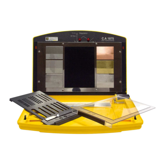
L’objectif est de sensibiliser les personnes au fait qu’une caméra infrarouge est un outil de mesure de précision qui nécessite une prise en main approfondie. Le banc didactique C.A 1875 est composé d’une plaque chauffante équipée de plusieurs cibles d'états de surface et de matériaux différents ainsi que d'écrans de test qui se fixent sur l’avant du banc à... - Page 7 Problèmes de positionnement Problème de réflexion Problème de transmission Problème de résolution spatiale Présentation du banc didactique thermographie C.A 1875 : 1 : Plaque chauffante 2 : LEDs d’indication de montée ou de descente en température 3 : Interrupteur Marche / Arrêt 4 : Connexion câble alimentation secteur...
-
Page 8: Caracteristiques
Français Présentation des écrans de test Ecran de test n° 2: Ecran de test n° 1 : Fentes de largeur variable Vitre plexiglas Présentation des cibles chaudes Plaque 4 : Plaque 1 : Cuivre Acier poli rouge Plaque 2 : Plaque 5 : Acier inox Laiton... -
Page 9: Caractéristiques Du Fusible
Dimensions : 5 x 20 mm Calibre : 0,5 A rapide – 250 V 4. MISE EN SERVICE Le banc didactique thermographie C.A 1875 doit être placé sur une surface plane. La plaque chauffante doit être perpendiculaire au plan de travail. -
Page 10: Manipulations
Français Une fois le banc positionné, branchez-le à une prise secteur équipée d'une terre et mettez en service avec le bouton Marche/Arrêt. Attendez quelques minutes que la plaque monte en température pour effectuer les premiers tests. T(° C) Régulation 60° Max Schéma de fonctionnement des LEDs et de la variation de température de la plaque chauffante. - Page 11 Français - La conduction - La convection - Le rayonnement Ces trois modes peuvent être présents simultanément et indépendamment l’un de l’autre. Un flux de chaleur est un terme d’énergie thermique par unité de temps. Un flux de transfert ne se produit que lorsqu’une différence de température est présente. L’énergie thermique est transférée d’un corps chaud vers un corps froid.
- Page 12 Français La convection naturelle: lorsqu'il existe une différence de température entre deux points d'un fluide, le fluide chaud aura tendance à monter sous l'effet de la poussée d'Archimède. Il y aura ainsi circulation naturelle du fluide sous l'effet de la chaleur qui, par ailleurs, sera transportée avec lui: on parle de convection naturelle.
- Page 13 Français Le rayonnement : cas du corps parfait, le corps noir. Tout corps à une température supérieure à 0 degré kelvin (zéro absolu, soit - 273,15° C) émet un rayonnement électromagnétique app elé rayonnement thermique. Le rayonnement infrarouge est le rayonnement électromagnétique dont la longueur d’onde est comprise entre 700 nanomètres et 1 millimètre.
- Page 14 Français C’est la loi de Stephan-Boltzmann qui permet de quantifier ces échanges. L’énergie E rayonnée par un corps s’écrit : E = S. σ. T Avec: E: énergie rayonnée exprimée en W / m². σ: constante de Stephan-Boltzmann = 5,6703 . 108 W.m S : surface du corps exprimée en m²...
- Page 15 Français Plus l’émissivité diminuera, plus le maximum de la courbe diminuera également. La loi de Stephan-Boltzmann devient alors : E = ε. S. σ. T L’émissivité est une caractéristique d’un matériau et de son état de surface. Plus un corps sera capable d’absorber de la chaleur, plus son émissivité sera proche de 1.
-
Page 16: Manipulations: Étude De L'influence De L'émissivité
Français 5.1.2 Manipulations: étude de l’influence de l’émissivité Manipulation 1 : Mise en avant des problèmes de mesure sur des matériaux d’émissivité différentes. Assurez-vous que le banc régule en température depuis quelques instants. Pointez la caméra vers la plaque chauffante, en s’assurant que vous êtes bien positionné... -
Page 17: Etude Du Corps Réel
Français 5.2 ETUDE DU CORPS REEL 5.2.1 La théorie Le corps noir est donc un objet théorique. On ne peut appliquer les formules précédentes à un objet réel que moyennant quelques corrections : les objets réels n’absorbent qu’une fraction α du rayonnement incident, en réfléchissant une partie ρ... - Page 18 Français Rayonnement de l’objet Rayonnement réfléchi de l’environnement sur l’objet Et le rayonnement total reçu par la caméra est donc : mesuré objet réfléchi ε. σ. (T ρ . σ. (T objet réfléchi D’où : = ε. σ. (T + ρ . σ. (T mesuré...
-
Page 19: Manipulations : Étude De L'influence De La Réflexion Et De La Transmission
Français 5.2.2 Manipulations : étude de l’influence de la réflexion et de la transmission Manipulation 3 : Mise en avant des problèmes de mesure liés aux phénomènes de réflexion Créez un nouveau dossier. - Positionnez la caméra en face de la plaque en aluminium : brillant, de faible émissivité... - Page 20 Français sous lequel un détecteur de la matrice voit une surface élémentaire (∆s) de la scène thermique. La difficulté pour définir IFOV tient au fait que les dimensions des capteurs matriciels ne sont pas standardisées. On ne désigne donc pas un objectif par sa distance focale, mais par l’angle FOV (Field Of View), sous lequel la caméra voit la scène thermique.
- Page 21 Français Schéma reprenant les différentes notions : Scène thermique rectangulaire ∆s carré (vue par la matrice rectangulaire) (vue détecteur carré) HFOV IFOV VFOV Application : voir annexe 3 exercice 6. Pouvoir de Résolution Spatiale de Mesure (PRSM). S’agissant de mesurer des températures et non plus de réaliser une image thermique, il faut s’intéresser à...
- Page 22 Français Cas n° 1 : Le fil est de la taille d’1 IFOV. En réalité, on a plus de risque Pour être certain de faire une mesure d’avoir cette configuration : correcte, il faudrait que le fil se positionne de la sorte : Aucun détecteur n’est recouvert Dans cette configuration, nous obtiendrons complètement donc on n’aura...
-
Page 23: Manipulation : Étude De La Résolution Spatiale
Français On n’est toujours pas certain de faire une mesure de température correcte. Cette configuration n’est également pas réaliste !! Cas n° 3 : Le fil est de la taille de 3 IFOV. N’importe où se positionne le fil, il y aura forcément un détecteur de recouvert ! La mesure est donc fiable. -
Page 24: Manipulations Sur Logiciel
Français A l’aide des curseurs, déterminez la température de chaque fente. Quelle est la conclusion ? - Positionnez la RayCAm à 30 cm de l'écran n° 2. Prenez un thermogramme de chaque série de fentes. A l’aide des curseurs, déterminez la température de chaque fente. Quelle est la conclusion ? - Positionnez la RayCAm à... - Page 25 Français - Insérez des points sur chaque matériaux et type de surface de chaque thermogramme. - Créez une zone tableau par thermogramme. Remplissez le tableau avec les éléments suivants : numéro et émissivité image IR, température et émissivité des points. - Modifiez l’émissivité...
-
Page 26: La Thermographie En Pratique
Français 5.5 LA THERMOGRAPHIE EN PRATIQUE 5.5.1 Modes de détermination de défaut. La thermographie absolue Ce mode renseigne sur l’état d’un composant ou d’un matériau, compte-tenu de ses conditions de fonctionnement du moment. La question qu’il faut alors se poser est : est-ce en deçà ou au-delà du maximum fourni par le constructeur ? Lorsque la thermographie IR est intégrée dans les procédures de maintenance prédictive, on peut tracer l’évolution temporelle de la température absolue, puis... -
Page 27: Applications
Français 20 ° C à 40 ° C Sérieux. Mesures correctives urgentes (max 1 mois) > 40 ° C Critique. Mesures correctives à prendre immédiatement (max 1 sem.) Application : voir annexe 3 exercice 10 5.5.2 Applications La maintenance électrique Les objectifs d’un tel contrôle sont de mettre en évidence, dans les infrastructures électriques en charge, des échauffements pouvant avoir diverses origines : mauvaises connexions,... - Page 28 Français permet le calcul direct de la température maximale observée et éventuellement la surchauffe. Un calcul complémentaire peut, dans le cas où le système n’est pas à sa charge normale, permettre d’estimer la surchauffe ramenée à son fonctionnement normal. On admet qu’un défaut est de nature résistive. L’écart brut de température doit être compensé...
-
Page 29: Réalisation D'un Rapport Q19
Français A l’aide de l’infrarouge il est aisé de visualiser la distribution de chaleur sur la façade d’un bâtiment et il est possible de localiser précisément les pertes de chaleur dues à un défaut d’isolation. On peut ainsi dresser un bilan thermique du bâtiment. - Page 30 Français • Communiquer à la société d’assurance un exemplaire de la déclaration Q19 dans les quinze jours après réception du rapport. Les engagements du thermographe: Noter, à partir de la liste des matériels à inspecter, les différentes observations essentielles à la compréhension et à la résolution des problèmes (intensité, remarques, type et urgence des anomalies) Garantir les compétences de l'opérateur: L'ensemble de l’équipe intervenante est habilité...
- Page 31 CONTROLE THERMOGRAPHIQUE Fiche d'anomalie N° : 1 Français Poste : Equipement : Charge : 100 % IR Info Value IrNo dist envtmp Date 2003-9-3 Time 12:52:39 Label Value Diagnostic : Max:Temp 101,38 Max:ems Recommandation : Max:dist CONCLUSION : ........................Contrôlé par : M....Réparé...
-
Page 32: Mise En Application
6.1 REPARATION Réparation sous garantie et hors garantie. Adressez vos appareils à l'un des Centres Techniques régionaux MANUMESURE, agréés CHAUVIN ARNOUX Renseignements et coordonnées sur demande : Tél. :02 31 64 51 43 Fax. : 02 31 64 51 09... -
Page 33: Changement Fusible
; des dommages dus à des chocs, chutes ou inondations. 8. POUR COMMANDER C.A 1875................... ….P01.6516.20 Fourni avec un cordon d’alimentation, deux écrans de test accessoire, une notice de fonctionnement incluant le manuel de TP dans une sacoche. - Page 34 Français ANNEXE 1 : DETERMINATION EMISSIVTE Il s’agit de la norme ASTM E1933-99A : Soit S1 la surface du matériau dont on cherche à déterminer l’émissivité. Appliquons sur S1 une couche de peinture noire S2 dont l’émissivité est connue. S1 et S2 étant dans les mêmes conditions environnementales, les deux surfaces sont à...
- Page 35 Français ANNEXE 2 : DETERMINATION TEMPERATURE REFLECHIE Il s’agit de la norme ASTM E1933-99A : 1) On place au plus près de la scène visée, avec la même orientation par rapport à la caméra, une feuille d'aluminium ménager préalablement froissée puis défroissée grossièrement.
- Page 36 Français ANNEXE 3 : EXERCICES D’APPLICATION Exercice 1 Mise en avant de conduction en thermographie IR : Thermogramme 1 Thermogramme 2 Commentez ces deux images. Exercice 2 Mise en avant des problèmes de convection forcée en thermographie IR. Thermogramme pris par grand vent Thermogramme pris par temps calme Commentez ces deux images.
- Page 37 Français Quelle est la température de ce corps ? Quelle est la longueur d’onde correspondant au maximum d’énergie rayonnée? Exercice 4 : D’après les estimations faites sur la terre, la surface du soleil est 6,1.10 et la puissance rayonnée est de 3,9.10 En supposant que le soleil est assimilé...
- Page 38 Français Selon les éléments horizontaux de la matrice Quelle est la plus petite surface détectable par la caméra ? Exercice 7 Quel est la largeur de la plus petite zone mesurable d par la RayCAm ? Quel est la largeur de la plus petite zone mesurable d par la RayCAm à...
- Page 39 Français Thermogramme 1 52,8° C 45,5° C 45° C Thermogramme 2 57,9° C 68° C 67,4° C Thermogramme 3 45,5° C 51,6° C 44,7° C...
- Page 40 Français Thermogramme 4 51,3° C 55,3° C 55,4° C Thermogramme 5 43,2° C 24,9° C Thermogramme 6 60,3° C 35,3° C...
- Page 41 Français Exercice 11 Déterminer les degrés d’urgence d’intervention des thermogrammes précédents sachant que : Thermogramme 1 pris à 60 % de la charge nominale Thermogramme 2 pris à 90 % de la charge nominale Thermogramme 3 pris à 85 % de la charge nominale Thermogramme 4 pris à...
- Page 42 Français ANNEXE 4 : SOLUTIONS Solution 1 Thermogramme 1 : Il s’agit de l’observation d’un réfractaire à l’aide d’une caméra infrarouge. A l’œil nu, on ne voit rien. Normalement, si la cheminée était bien isolée, nous devrions avoir une température uniforme à la surface du réfractaire, donc une couleur uniforme. Or nous pouvons voir verticalement un trait de couleur plus claire, donc de température plus chaude.
- Page 43 Français Solution 3 Question a Loi de Stéfan : P = S ε σ T Avec ε = 1 car corps noir σ = 5,68.10 Constante de Boltzman S = π R surface d’une boule D’où : = P / S ε σ =>...
- Page 44 Français En première conclusion, nous pourrions dire que les yeux de la personne sont plus froids que le restant de son visage. Cette analyse est bien entendue fausse : il s’agit simplement d’un problème de transmission ! En effet, il n’est pas possible d’observer et de mesurer des températures à...
- Page 45 Français D’où : = 0,218 mm ∆s Solution 7 Question a L’IFOV de la RayCAm est de 2,2 mrad. La distance minimale de focalisation est de 10 cm. La plus petite zone mesurable correspond à la valeur de 3 IFOV. Nous avons donc: = 3 x IFOV 10 cm...
- Page 46 Français Question b Pour être certain de faire une mesure correcte, on doit avoir au maximum: = 3 x ∆s Câble De plus, selon l’IFOV de la caméra: à 1 m ∆s = 2,2 mm à d ∆s Câble On a alors : = ∆s / 2,2 = (d...
- Page 47 Français = (( (4 x P) / π ) / 3 ) / 2,2 D’où : = 0,21 m = 21 cm Pour effectuer une mesure correcte, il faut que la caméra soit entre 10 cm et 21 cm de la cible. Question b Pour être certain de faire une mesure correcte, on doit avoir au maximum: = 3 x ∆s...
- Page 48 Français Thermogramme 3 Selon la température des curseurs, déterminons la différence de température entre P01 et P02 : ∆T = T – T = 51,6 – 45,5 ∆T = 6,1 ° C D’où un degré de criticité de niveau 0, à suivre. Thermogramme 4 Selon la température des curseurs, déterminons la différence de température entre P01 et P02 :...
- Page 49 Français L’écart de temperature mesurée était de 7,3° C Ainsi : ∆T effectif = ∆T brut x (100/60)² = 7,3 x (100/60)² = 20,3 ° C En réalité, le degrés de criticité est de niveau 2, il est nécessaire de planifier une action corrective dans les 1 à...
- Page 50 Français I nominal /I mesuré = 100/40 L’écart de température mesurée était de 4° C Ainsi : ∆T effectif = ∆T brut x (100/40)² = 4 x (100/40)² = 25 ° C Après une première approche où il paraissait qu’il n’y ait aucun défaut apparent, nous nous apercevons qu’il s’agit d’un degré...
- Page 51 English Français You have just purchased a C.A 1875 thermography tutorial bench and we thank you for your confidence. For best results from your instrument: • read these operating instructions carefully, • observe the precautions for use MEANINGS OF THE SYMBOLS USED Selective sorting of wastes for the recycling of electrical and electronic equipment within the European Union.
- Page 52 English Français CONTENTS 1. INTRODUCTION 2. PRESENTATION 3. CHARACTERISTICS General characteristics of the bench ......... 56 Characteristics of the fuse ............57 4. COMMISSIONING 5. MANIPULATIONS THERMAL TRANSFERS............58 5.1.1 Theory……………………………………………………………58 5.1.2 Manipulations: study of the influence of emissivity………….63 Study of the real body..............64 5.2.1 Theory……………………………………………………………64 5.2.2...
- Page 53 English Français APPENDIX 1: DETERMINATION OF EMISSIVITY APPENDIX 2: DETERMINATION OF REFLECTED TEMPERATURE APPENDIX 3: APPLICATION EXERCISES APPENDIX 4: SOLUTIONS...
-
Page 54: Introduction
English Français 1. INTRODUCTION Infrared thermography detection technology has become an essential means of guaranteeing the safety of industrial production conditions. It is used in sectors of industry as varied as metallurgy and steel-making, electric power, the oil industry, automation, the extraction of natural gas, the transport industry, and other professions active in fire fighting and border surveillance. -
Page 55: Presentation
The objective is to make people aware that an infrared camera is a precision measurement tool that requires much training and experience to use correctly. The C.A 1875 tutorial bench comprises a hot plate with several targets having different surface conditions and made of different materials, along with test screens that are affixed to the front of the bench using magnets. - Page 56 English Français Presentation of the C.A 1875 thermography tutorial bench: 1: Hot plate 2: LEDs indicating rising or falling temperature 3: On / Off switch 4: Power cord connection 5: Fuse compartment 6: 10: Plates of different materials 7: Cover protecting the bench...
-
Page 57: Characteristics
English Français Presentation of the hot targets Plate 1: Plate 4: Polish steel Red copper Plate 2: Plate 5: Stainless steel Brass Plate 3: Plate 6: Laminate Aluminium Black plate having an emissivity of 0.95 3. CHARACTERISTICS 3.1 GENERAL CHARACTERISTICS OF THE BENCH Power supply: 230 V 50 / 60 Hz... -
Page 58: Characteristics Of The Fuse
Rating: 0.5 A fast-blow – 250 V 4. COMMISSIONING The C.A 1875 thermography tutorial bench must be placed on a flat, level surface. The hot plate must be perpendicular to the work top. Once the bench is in place, connect it to a mains outlet with an earth and power up using the On/Off button. -
Page 59: Manipulations
English Français When the bench is started up, L1 lights until the plate reaches approximately 55° C. When this temperature is reached, L2 lights and the plate cools to approximately 50° C. Heating resumes, with the lighting of L1, and so on. This cycle continues indefinitely for as long as the bench is in operation. - Page 60 English Français agitation of the atoms located at the heated end of the bar increases and is transmitted step by step in the direction opposite the thermal gradient. Thermal gradient Temperature rise at the end of the bar Application: see Appendix 3, exercise 1 Convection.
- Page 61 English Français Forced convection is an undesirable phenomenon in infrared thermography. This is because forced convection cools the surface of a body without for all that altering its internal temperature. For example, wind is a vector of forced convection. When there is wind, people feel cooler and their skin temperature may fall.
- Page 62 English Français Wien's law gives the wavelength (in micrometers) corresponding to the maximum radiated energy of a black body at a specified temperature T (in Kelvin). 2898 λ The wavelength of the infrared radiation maximum decreases as the temperature of the black body increases.
- Page 63 English Français Emissivity The emissivity of a material (often written ε), is the ratio of the energy it radiates to the energy a black body would radiate at the same temperature. It is therefore a measure of the capacity of a body to absorb and re-emit radiant energy. The emissivity is a quantity between 0 and 1.
-
Page 64: Manipulations: Study Of The Influence Of Emissivity
English Français Thus, to make a valid measurement, it is necessary to place the camera perpendicular to the measurement target (facing it squarely) so that the emissivity entering the camera reflects reality. A tolerance of +/- 45° is accepted. The emissivity is a fundamental parameter in thermography. It is essential to set it correctly before making any measurement. -
Page 65: Study Of The Real Body
English Français What do you observe? What conclusion can you draw? Manipulation 2: Highlighting the problems of positioning with respect to the target. Create a new folder. - Aim the camera at the hot plate, making sure that you are correctly positioned perpendicular to the bench. - Page 66 English Français The principle of the conservation of energy yields the following equation: α . I(T) + ρ . I(T) + τ . I(T) = I(T) , or α + ρ + τ = 1 At equilibrium, the object emits ε (T) the same quantity of energy as it absorbs α (T). This gives the following equation: α...
-
Page 67: Manipulations: Study Of The Influence Of Reflection And Transmission
English Français Whence: = ε. σ. (T + ρ . σ. (T measured object reflected = ε. σ. (T + (1 – ε) . σ. (T object reflected To obtain the temperature of the object, it is therefore necessary to enter the emissivity and reflected temperature parameters in the RayCAm. -
Page 68: Optics And Thermography Camera
English Français - Make a temperature measurement on the black plate in the centre, the emissivity of which is 0.95. - Place test screen number 1 (plexiglas window) on the zone provided for it on the bench. Wait 2-3 minutes for the temperature of the environment to become uniform. Target the black plate through the plexiglas pane and make a temperature measurement. - Page 69 English Français HFOV x π x 1000 VFOV x π x 1000 IFOV (mrad) = = PRSO ndH x 180° ndV x 180° The IFOV corresponds to the spatial resolution of the camera, i.e. to the dimension of the zone a detector can measure. This dimension depends on the camera's distance from the target.
- Page 70 English Français Case no. 1: The wire is the size of 1 IFOV. In reality, there is a greater risk of To be sure of making a valid having this configuration: measurement, the wire must be positioned like this: No detector is completely covered: no In this configuration, we find valid response on any of the detectors!!! the correct temperature...
-
Page 71: Manipulation: Study Of Spatial Resolution
English Français We are still not sure of making a valid temperature measurement. This configuration too is unrealistic!! Case no. 3: The wire is the size of 3 IFOVs. Anywhere the wire is placed, there will necessarily be at least one detector covered! The measurement is therefore reliable. -
Page 72: Manipulations On Software
English Français - Position the RayCAm 30 cm from screen no. 2. Make a thermogram of each series of slits. Using the cursors, determine the temperature of each slit. What is your conclusion? - Position the RayCAm 80 cm from screen no. 2. Make a thermogram of each series of slits. - Page 73 English Français - Create one table zone per thermogram. Enter the following elements in the table: number and emissivity of IR image, temperature and emissivity of the points. - Modify the emissivity of the points until you obtain the temperature of the black plate.
-
Page 74: Thermography In Practice
English Français 5.5 THERMOGRAPHY IN PRACTICE 5.5.1 Fault determination modes. Absolute thermography This mode provides information about the condition of a component or of a material given its operating conditions at the time. The question that must then be asked is: is this below or above the maximum indicated by the manufacturer? When IR thermography is incorporated in predictive maintenance procedures, it is possible to trace the time course of the absolute temperature, then extrapolate in... -
Page 75: Applications
English Français 20° C to 40° C Serious. Corrective measures are urgent (max. 1 month) > 40° C Critical. Corrective measures must be taken immediately (max. 1 week) Application: see appendix 3, exercise 10 5.5.2 Applications Electrical maintenance The purpose of an inspection of this type is to detect, in electrical infrastructure under load, temperature rises of various origins: incorrect connections, overloads,... - Page 76 English Français It is assumed that a fault is resistive in character. The raw temperature difference must be corrected for the load: ∆T = ∆T raw x (I nominal /I measured )² effective It is the effective difference that must be considered when classifying the fault. It remains to be determined how urgent maintenance is.
-
Page 77: Producing A Q19 Report
English Français o Locating leaks: pipes that convey a hot fluid and are just below the surface of a floor are readily visualized, and it is possible to precisely locate leaks in a network. o Location of heating elements: it may be necessary to locate pipes precisely with a view to drilling into a floor for work. - Page 78 English Français Guarantee the competence of the operator: Each member of the inspection team is BR H1V accredited and holds the certificate of "Operator for the inspection of electrical installations by infrared thermography" issued by the CNPP. Provide, as soon as the inspection is over, a first oral or written report describing the course of the inspection and report the most urgent anomalies.
- Page 79 THERMOGRAPHIC INSPECTION Anomaly sheet no. 1 Français Station: Equipment: Load: 100% IR Info Value IrNo dist envtmp Date 2003-9-3 Time 12:52:39 Label Value Diagnostic: Max:Temp 101.38 Max:ems Recommendation: Max:dist CONCLUSION: ........................Checked by: Mr....Inspected on: ../../2... by Mr ..... Repair inspected on ../../2...
-
Page 80: Application
English Français 5.6.2 Application Using an electrical cabinet present in the room, make thermograms of the installation and prepare a report based on the Q19 model. 6. MAINTENANCE The manufacturer cannot be held liable for any accident that occurs following a repair done by a party other than its customer service department or an approved repairer. -
Page 81: Warranty
8. TO ORDER C.A 1875................... ….P01.6516.20 Supplied with a power cord, two accessory test screens, operating instructions including the problems manual in a carrying bag. - Page 82 English Français APPENDIX 1: DETERMINATION OF EMISSIVITY The relevant standard is ASTM E1933-99A: Let S1 be the surface area of the material of which it is desired to determine the emissivity. Apply to S1 a coat of black paint S2 of which the emissivity is known.
- Page 83 English Français APPENDIX 2: DETERMINATION OF REFLECTED TEMPERATURE The relevant standard is ASTM E1933-99A: 1) A sheet of ordinary aluminium foil, crumpled and flattened, is placed as close as possible to the scene viewed, in the same orientation with respect to the camera. ε...
- Page 84 English Français APPENDIX 3: APPLICATION EXERCISES Exercise 1 Highlighting of conduction in IR thermography: Thermogram 1 Thermogram 2 Comment on these two images. Exercise 2 Highlighting of the problems of forced convection in IR thermography. Thermogram made in high wind Thermogram made in still air Comment on these two images.
- Page 85 English Français What is the temperature of this body? What is the wavelength corresponding to the maximum of radiated energy? Exercise 4: Based on estimates made on Earth, the area of the sun is 6.1 x 10 and its radiated power is 3.9 x 10 Regarding the sun as a black body: What is its surface temperature? What is the wavelength corresponding to the maximum of radiated...
- Page 86 English Français For the vertical elements of the matrix For the horizontal elements of the matrix What is the smallest area the camera can detect? Exercise 7 What is the width d of the smallest zone the RayCAm can measure? What is the width d of the smallest zone the RayCAm can measure at 50 cm?
- Page 87 English Français Thermogram 1 52.8° C 45.5° C 45° C Thermogram 2 57.9° C 68° C 67.4° C Thermogram 3 45.5° C 51.6° C 44.7° C...
- Page 88 English Français Thermogram 4 51.3° C 55.3° C 55.4° C Thermogram 5 43.2° C 24.9° C Thermogram 6 60.3° C 35.3° C...
- Page 89 English Français Exercise 11 Determine the degrees of urgency of maintenance of the thermograms above assuming that: Thermogram 1 was made at 60% of nominal load Thermogram 2 was made at 90% of nominal load Thermogram 3 was made at 85% of nominal load Thermogram 4 was made at 40% of nominal load Thermogram 5 was made at 90% of nominal load Thermogram 6 was made at 100% of nominal load...
- Page 90 English Français APPENDIX 4: SOLUTIONS Solution 1 Thermogram 1: This concerns the observation of a refractory using an infrared camera. The naked eye sees nothing. Normally, if the stack were correctly insulated, the temperature of the surface of the refractory should be uniform, and so its colour should be uniform. But we see a vertical line that is lighter in colour, and therefore hotter.
- Page 91 English Français Solution 3 Question a Stefan's law: P = S ε σ T With ε = 1 because black body σ = 5.68 x 10 Boltzmann's constant S = π R surface of a ball Whence: = P/S ε σ =>...
- Page 92 English Français Off hand, we might conclude that the person's eyes are colder than the rest of the person's face. This analysis is of course false: it simply reveals a transmission problem! As it happens, it is not possible to observe and measure temperatures through glass! Whence this false measurement! Solution 6 Question a...
- Page 93 English Français At 10 cm ∆s = x mm Whence: ∆s = 0.218 mm Solution 7 Question a The IFOV of the RayCAm is 2.2 mrad. The minimal focal length is 10 cm. The smallest zone that can be measured corresponds to 3 IFOV. We therefore find: = 3 x IFOV 10 cm...
- Page 94 English Français The camera must be at a distance of not more than 30 cm to make a valid measurement. Question b To be sure of making a valid measurement, the following value must not be exceeded: = 3 x ∆s Cable In addition, based on the IFOV of the camera: at 1 m...
- Page 95 English Français To be sure of making a valid measurement, the following value must not be exceeded: = 3 x ∆s Cable In addition, based on the IFOV of the camera: at 1 m ∆s = 2.2 mm at d ∆s Cable It follows that:...
- Page 96 English Français From the temperatures of the cursors, let us determine the difference of temperature between P01 and P02: ∆T = T – T = 68 – 57.9 ∆T = 10.1° C Whence a degree of criticality of level 1; plan corrective action in from 3 to 6 months.
- Page 97 English Français Solution 11 Thermogram 1 We find the equation: ∆T effective = ∆T raw x (I nominal /I measured )² The installation was thermographed at 60% of its load, whence: I nominal /I measured = 100/60 The measured temperature difference was 7.3° C ∆T effective = ∆T raw x (100/60)²...
- Page 98 English Français There is no significant influence of the load. Thermogram 4 We find the equation: ∆T effective = ∆T raw x (I nominal /I measured )² The installation was thermographed at 40% of its load, whence: I nominal /I measured = 100/40 The measured temperature difference was 4°...
- Page 99 English Français...
- Page 100 Tel: +86 21 65 21 51 96 - Fax: +86 21 65 21 61 07 SCANDINAVIA - CA Mätsystem AB USA - Chauvin Arnoux Inc - d.b.a AEMC Instruments Box 4501 - SE 18304 TÄBY 200 Foxborough Blvd. - Foxborough - MA 02035...
Need help?
Do you have a question about the C.A 1875 and is the answer not in the manual?
Questions and answers