
Related Manuals for nilan VPM 600


Summary of Contents for nilan VPM 600
- Page 1 INSTALLATION AND SERVICE INSTRUCTIONS CTS602I HMI BY NILAN VPM 600-2200 (English) Version 3.00 - 03.06.2020...
-
Page 2: Table Of Contents
Opening the unit ................................................... Unit in standby ..................................................Unit type ........................................................ Product description ................................................Dimensional drawing for VPM 600 ........................................Dimensional drawing for VPM 700-800-1000 ................................... Dimensional drawing for VPM 1200-1500 ....................................Dimensional drawing for VPM 2200 ........................................Placing of vibration absorbers .......................................... - Page 3 VPM 600-2200 (English) BY NILAN Wall bracket ..................................................Electrical connection accessories ........................................... Electrical after-heating element (accessory) ..................................... Water after-heating element (accessory) ..................................... Plumbing installation Condensate drain ..................................................Important information ..............................................Connecting condensate drain ..........................................Plumbing connections - accessories ........................................Water trap with ball (optional) ..........................................
-
Page 4: Power Supply
Safety Power supply Always disconnect the power supply for the unit if an error occurs that cannot be rectified via the control panel. If an error occurs on electrically conductive parts of the unit, always contact a certified electrician to rectify the error. -
Page 5: General Information Introduction
In order for the unit to be able to operate correctly and to secure the safety of persons and equipment, the instructions must be followed. Nilan A/S disclaims all responsibility for damages resulting from the unit and/or accessories having been used in conflict with the directions and instructions of this manual. -
Page 6: Data Plate
2. unit order no. 3. unit serial no. Note: When contacting Nilan A/S with questions about the product, please be ready to quote unit type, order no. and serial no. This information will enable the service department to identify relevant information about your unit. -
Page 7: Unit Type
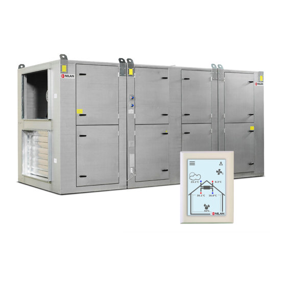
Unit type Product description The VPM 600-2200 series is a ventilation and heat recovery unit with cooling and heating functions developed especially for commercial constructions with an air exchange requirement of up to 22,000 m³ per hour. A VPM unit removes the "used", humid air from the building and supplies new, "fresh" air in turn. The energy in the extract air is recovered and transferred to the supply air via a unique combination of active (heat pump) and passive (heat pipe) heat recovery. - Page 8 Outdoor air duct connection Duct connection supply air Duct connection extract air Duct connection discharge air Outdoor air filter Extract air filter Supply air fan Extract air fan Electrical connections 10. Connection of HMI control panel 11. Automation (inside the electrical cabinet) 12.
-
Page 9: Dimensional Drawing For Vpm 600
VPM 600-2200 (English) BY NILAN Dimensional drawing for VPM 600 The dimensioned drawing below is for a left-facing version. All measurements are in mm. 3910 2000 Supply air Outdoor air (supply) Extract air Discharge (extract) 1050 1225... -
Page 10: Dimensional Drawing For Vpm 700-800-1000
Dimensional drawing for VPM 700-800-1000 The dimensioned drawing below is for a left-facing version. All measurements are in mm. 4290 1140 2000 1140 Outdoor air Supply air (supply) Discharge Extract air (extract) 1210 1415 1000 1000... -
Page 11: Dimensional Drawing For Vpm 1200-1500
VPM 600-2200 (English) BY NILAN Dimensional drawing for VPM 1200-1500 The dimensioned drawing below is for a left-facing version. All measurements are in mm. 4440 1215 2000 1215 Supply air Outdoor air (supply) Extract air Discharge air (extract) 1315 1490... -
Page 12: Dimensional Drawing For Vpm 2200
Dimensional drawing for VPM 2200 The dimensioned drawing below is for a left-facing version. All measurements are in mm. 4850 1370 21 00 1370 Supply air Outdoor air (supply) Extract air Discharge air (extract) 1470 1620 1400 1400... -
Page 13: Placing Of Vibration Absorbers
VPM 600-2200 (English) BY NILAN Placing of vibration absorbers VPM 600 310kg 720kg 310kg With base: 8 brown 100x100x25 + 4 red 100x100x25 Placed both front and rear Without base: 4 red 100x100x25 + 8 brown 100x100x25 VPM 700-800-1000 425kg... -
Page 14: Functional Diagram Vpm 600-2200
Functional diagram VPM 600-2200 Heating Cooling Connections Automation 1: Outdoor air T1: Outdoor air sensor 2: Supply air T2/T7: Supply air sensor 3: Extract air T9: After-heating element frost protection 4: Discharge air T5: Condenser sensor 5: Condensate drain T6: Evaporator sensor... -
Page 15: Accessories
VPM 600-2200 (English) BY NILAN Accessories CO2 sensor With a CO -sensor installed externally or as an integral part of the unit, the fan speed can be pre-programmed to run at higher levels when the extract air has high 2. CO level can be programmed. -
Page 16: Water After-Heating Element
This will cause water damage. Nilan’s water trap contains a ball that ensures that no air is sucked into the unit and that condensate water can drain freely. -
Page 17: Handling
• Lift with transport hooks in pre-assembled lifting eyes. The VPM 600-3200 is equipped with lifting eyes. If chains or straps are used directly on the brackets, the mutual angle must be greater than 60 °. If this is impossible due to lack of space, a lifting beam or similar must be used. -
Page 18: Installation
There must be enough space to clean the unit easily. There must therefore be space for installing water traps in the condensate drains. X = Recommended service distance. Unit X (in mm) VPM 600 VPM 700 VPM 800 VPM 1000 VPM 1200... -
Page 19: Positioning And Installation Of Unit
VPM 600-2200 (English) BY NILAN Positioning and installation of unit The arrangement is shown for a unit with a discharge module. If the supplied unit does not have this, step 10 is ignored. Step 1 Foundation is placed in the desired place. - Page 20 The center section is placed exactly in the middle of the space set aside on the base. All models larger than the VPM 600 are equipped with lifting eyes. If chains or straps are used directly on the brackets, the mutual angle must be greater than 60 °.
- Page 21 VPM 600-2200 (English) BY NILAN Step 7: The filter / fan sections are pulled, with the help of the enclosed brackets / bolts, together with the center section. The brackets are placed in the square grooves at the bottom of the sections.
- Page 22 Filter-/fan- Middle- Step 9: unit section The drop catcher is mounted in the VPM module. a. Drop catcher b. Evaporator c. Condensate tray d. EC-Fan Step 10: If the unit comes with a discharge module, repeat the steps for the discharge module.
-
Page 23: Outdoor Installation
Guylines can be mounted in the lifting eyes, which is attached securely to the ground. It is possible to buy a storm bracket from Nilan, article number 77223. The bracket attaches the unit together with the base. a. Opel screws (6.3 x 19) with washer Drill with 4.5 mm bit. -
Page 24: Electrical Installation Electrical Connections
Electrical installation Electrical connections Safety All work must be carried out by suitably qualified persons and in compliance with existing legislation and regulations. It is important that the power supply is disconnected when doing work to the electrical components of the unit. -
Page 25: Electrical Connection Unit
VPM 600-2200 (English) BY NILAN Electrical connection unit Power supply The power supply, including the safety switch, must be installed by a certified electrician. Connect the unit to 3x400V+N+J. See also the wiring diagram supplied with the unit. Unit The illustration shown is for a left-facing version:... -
Page 26: Control Panel
Control panel CTS602i HMI Touch With the CTS602i HMI Touch panel, Nilan's units can be controlled on-site. The control panel comes connected to the CTS602i control system in the unit via the connection box on the side of the unit. It is supplied with a 3 meter Cat.5e cable of the type 4x2x0.5mm twisted pair. -
Page 27: Wall Bracket
VPM 600-2200 (English) BY NILAN Wall bracket Mount the HMI panel on the wall using the integrated wall bracket. The panel should be placed in a visible spot so it is possible to change settings and to monitor warnings or alarms regarding operation of the unit. -
Page 28: Electrical Connection Accessories
Installation of communication cable on the circuit board should be done in accordance with the wiring diagram. The electrical after-heating element type EB for the VPM 600-2200 series comes built into the unit, if you have opted to have this added. -
Page 29: Water After-Heating Element (Accessory)
VPM 600-2200 (English) BY NILAN Water after-heating element (accessory) Water-heating surface and mixing loop incl. circulation pump is built into the unit from the factory if purchased together with the unit. If the water-after-heating surface is retrofitted, the connection of the circulation pump must be carried out by an authorized electrician. -
Page 30: Plumbing Installation
Nilan can supply a water trap with a ball. The ball ensures that no air is drawn into the unit through the condensate drain if the water trap dries out. This means that water in the condensate tray can drain away, which makes it unnecessary to check the condensate drain quite as often. -
Page 31: Plumbing Connections - Accessories
VPM 600-2200 (English) BY NILAN Plumbing connections - accessories Water trap with ball (optional) Possible connections with Nilan’s water trap: 1. Water trap with Ø32 mm spout 2. Reducing fitting for Ø20 mm 3. Reducing fitting for ¾" RG 4. Reducing fitting for ½" tube Dimensional drawing: All measurements are in mm. -
Page 32: Water After-Heating Element (Accessory)
Water after-heating element (accessory) The mixing loop must be connected up to the heating element by a certified plumber. If the unit or the external pipe installations are installed outdoors or outside the building's climate shield, the installations must be protected against frost. The unit comes with an integral heating element if you have chosen this added feature. - Page 33 5. Calibration runs automatically for up to 6 minutes (the diode flashes during calibration. After completion, it stays on). 6. Put the cover on the actuator. Indicative performance data for integral water after-heating elements in VPM 600 The data listed in the table are based on a temperature before the heating element of 8°C. Supply air...
- Page 34 7500 22.3 37.7 29.8 1628 10000 20.6 44.3 47.8 1914 12500 19.4 49.9 68.9 2156 The heating element has two rows of pipes and a 3/4" RG connection. Regulation valve (accessory): Add when ordering. Indicative performance data for integral water after-heating elements in VPM 1200-1500 The data listed in the table are based on a temperature before the heating element of 8°C.
- Page 35 VPM 600-2200 (English) BY NILAN Regulation valve (accessory): Add when ordering.
-
Page 36: Ventilation Installation
Balancing Important information To ensure the ventilation system operates optimally, it is important that it is balanced correctly. Nilan A/S recommends that this is done by professionals. If a pressure control system has been purchased additionally, set the duct pressure in the pressure control boxes when balancing the unit. -
Page 37: Vpm 700
VPM 600-2200 (English) BY NILAN VPM 700 Assessment of SEL value at various airflow / pressure losses. VPM700, Air performance curves 1100 Capacity Curve 1000 Pressure drop water coil [Pa] SFP [J/m3] 2500 2100 1800 1200 4500 5500 6500 7500... -
Page 38: Vpm 1200
VPM 1200 Assessment of SEL value at various airflow / pressure losses. VPM1200, Air performance curves 1400 Capacity Curve 1200 Pressure drop water coil [Pa] SFP [J/m3] 1000 2500 2100 1800 1200 2500 4500 6500 8500 10500 12500 14500 16500 VPM 1500 Assessment of SEL value at various airflow / pressure losses. -
Page 39: Vpm 2200
VPM 600-2200 (English) BY NILAN VPM 2200 Assessment of SEL value at various airflow / pressure losses. VPM2200, Air performance curves 1600 Capacity Curve 1400 Pressure drop water coil [Pa] 1200 SFP [J/m3] 1000 2500 2100 1800 1200 3000 8000... -
Page 40: Maintenance And Cleaning
In order to ensure optimal operation and long durability of the unit as well as maximum hygiene standards, it is important to maintain and clean the unit as recommended by Nilan A/S. The schedule below provides indicative intervals for maintenance of the unit under normal operating conditions. -
Page 41: Replacement Of Filters
Also remember safety switch for any electric heater. Nilan A/S recommends that, as a minimum, you use filters of the types ISO ePM10 >60% filter (M5) or ISO ePM1 >50% filter (F7). Incorrect filters can cause leakage in the unit and reduce the filtration function. -
Page 42: Ordering Spare Parts
Ordering spare parts Filters VPM 600 Type Numbers per air line Nilan article number ISO ePM10 >60% filter (M5) 3888 ISO ePM1 >50% filter (F7) 3901 Filters VPM 700-800-1000 Type Numbers per air line Nilan article number ISO ePM10 >60% filter (M5) 3913 ISO ePM1 >50% filter (F7) - Page 43 VPM 600-2200 (English) BY NILAN...
Need help?
Do you have a question about the VPM 600 and is the answer not in the manual?
Questions and answers