Gymstick PRO20.0 User Manual
Hide thumbs
Also See for PRO20.0:
- User manual (37 pages) ,
- User manual (21 pages) ,
- User manual (20 pages)

Subscribe to Our Youtube Channel
Related Manuals for Gymstick PRO20.0


Summary of Contents for Gymstick PRO20.0
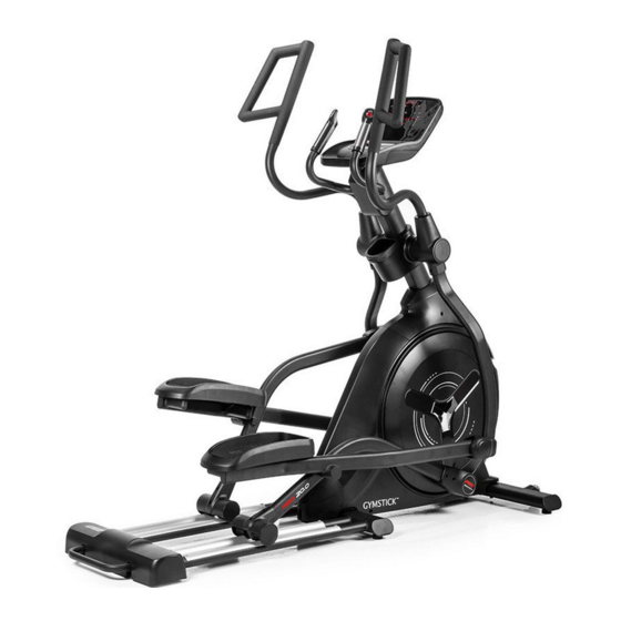
- Page 1 PRO20.0 CROSSTRAINER USER MANUAL IMPORTANT: Read all instructions carefully before using this product. Retain this owner’s manual for future reference. The specifications of this product may vary from this photo, subject to change without notice.
-
Page 2: Table Of Contents
BEFORE YOU BEGIN Thank you for choosing the Gymstick PRO20.0 Crosstrainer. We take great pride in producing this quality product and hope it will provide many hours of effective exercise to make you feel better, look better and enjoy life to its fullest. -
Page 3: Safety Instructions
14. Before exercising, always do warm-up and stretching first. 15. Maximum user weight: 180 kg WARNING! BEFORE BEGINNING THIS OR ANY EXERCISE PROGRAM, CONSULT YOUR PHYSICIAN FIRST. THIS IS ESPECIALLY IMPORTANT FOR INDIVIDUALS OVER THE AGE OF 35 OR PERSONS WITH PRE-EXISTING HEALTH PROBLEMS. PRO20.0 CROSSTRAINER... -
Page 4: Exploded Drawing
EXPLODED DRAWING PRO20.0 CROSSTRAINER... - Page 5 M8*1.25*120L 4PCS M8*1.25*70L 2PCS D18*D8.5*1.2T 4PCS D15.4*D8.2*2T 8PCS M8*1.25*55L 2PCS step2 M8*1.25*25L 4PCS step3 M8*1.25*20L 4PCS M6*1.0*15L 8PCS step4 M12*1.75*12T 4PCS M12*1.75*70L 4PCS step5 D22*D8.5*1.5T 6PCS M8*1.25*50L 6PCS M8*1.25*8T 6PCS step7 M5*0.8*12L 10PCS step6 M5*0.8*12L 8PCS ST4.2*15L 18PCS (MM) PRO20.0 CROSSTRAINER...
-
Page 6: Parts List
Rear stabilizer inside cover Water bottle holder (front) Water bottle holder (rear) Water bottle Hand pulse cable upper cover Hand pulse cable lower cover Dip foam(left) Dip foam(right) Pedals Pedal pads PRO20.0 CROSSTRAINER... - Page 7 6203-2RS ,SKF Anti-loose nut M8*1.25*8T Flat washer D28*D8.5*3T Hex nut M8*1.25*6T Sliding beam welding set Plastic flat washer D50*D10*1.0T Anti-loose nut M6x1.0x6T Bolt M6*75L Fixing sheet 20*27*4T Bolt M6x1.0x15L Bolt M6*1*5T Bolt M8x1.25x20L Hex nut M8*1.25*8T Screw ST4.2*15L PRO20.0 CROSSTRAINER...
- Page 8 Chargeable battery Fixing plate(1) Connecting cable(2) 1000L Flat washer D15*D5.2*1.0T Flat washer D34*D26*2T Bolt M8*1.25*20L Flat washer D18*D8.5*1.2T Computer fixed base welding set Bolt M10*1.5*75L Flat washer D20*D11*2T Hex nut M10*1.5*10T D6*26.5*7.7 Screw ST4*1.41*12L Bolt M8*1.25*55L PRO20.0 CROSSTRAINER...
-
Page 9: Assembly Instruction
(4) • bolt (5) 2. Assemble the sliding beam welding set (87) to the main frame (1) with: • bolt (147) • bolt (3) • flat washer (7) • spring washer (4) M8*1.25*120L M8*1.25*70L D15.4*D8.2*2T D18xD8.5x1.2T M8*1.25*55L PRO20.0 CROSSTRAINER... - Page 10 2. Assemble the handlebar post (11) to the main frame (1) with: • bolt (119) • spring washer (4) • flat washer (7) 3. Use bolt (97) to the fix the rear modified cover (33). M8*1.25*25L D15.4*D8.2*2T D18xD8.5x1.2T M5*0.8*12L step2 PRO20.0 CROSSTRAINER...
- Page 11 ASSEMBLY INSTRUCTION STEP 3. 1. Assemble the left and right movable support welding set (12L and 12R) to the handlebar post (11) with bolt (6). As shown in figure below. M8*1.25*20L step3 PRO20.0 CROSSTRAINER...
- Page 12 3. Assemble the pedals (44) to the right pedal bracket welding set (15R) with: • cross bolt (128), as shown in figure 4-3 (a) 4. Assemble the pedal pads (45) to pedals (44) as shown in figure 4-3 (b). M12*1.75*70L D24*D13.5*D2.5T M12*1.75*12T M6*1.0*15L step4 PRO20.0 CROSSTRAINER...
- Page 13 (8), curved washer (9), anti-loose nut (10) as shown in figure 5-1 2. Assemble the left moving handlebar (13L) to the left movable support welding set (12L), with: • bolt (8), curved washer (9), anti-loose nut (10) as shown in figure 5-2 M8*1.25*50L D22*D8.5*1.5T M8*1.25*8T step5 PRO20.0 CROSSTRAINER...
- Page 14 2. Assemble the computer (19) to the handlebar post (11) using bolt (97) as shown in figure 6-2. 3. Assemble the computer back cover (118) to the handlebar post (11) with bolt (97), figure 6-3. M5*0.8*12L 6-2 6-3 11 97 step6 PRO20.0 CROSSTRAINER...
- Page 15 5. Fix the front foot cover left (68L) to the front cover right (68R), with screw (96), figure 7-5. 6. Assemble the roller wheel cover (63) with 2 pcs bolt (97), figure 7-6. 7. Fix the 2 pcs axle cover (71), with bolt (97), as shown in figure 7-7. x 18 ST4.2*15L x 10 M5*0.8*12L step7 PRO20.0 CROSSTRAINER...
- Page 16 ASSEMBLY INSTRUCTION STEP 8. 1. Insert the power cord. 2. Adjust the ground wheels at the same height. step8 PRO20.0 CROSSTRAINER...
-
Page 17: Computer Operation Instructions
In setting mode or in selection mode, press to go back to initial training mode. If keep pressing this button 2s, computer will restart. RECOVERY To test heart rate recovery status. BODY FAT To test body fat % when press the BODY FAT button in standby mode. PRO20.0 CROSSTRAINER... - Page 18 Image 5. Image 6. Image 7. Power off If without RPM input for 4 minutes, LED-display will be closed and the computer will be in power off -mode. If RPM is detected again, the computer will wake up. PRO20.0 CROSSTRAINER...
- Page 19 “START/STOP” to start workout (in break mode the user can choose to adjust the “TIME” value). In START status, user can adjust RESISTANCE level. During workout, press “START/STOP” and the computer will enter into break mode, press “RESET” leave this mode. Image 11. Image 12. PRO20.0 CROSSTRAINER...
- Page 20 “TIME” (image14), if no value is set, press “START” to enter into working mode. In START mode user can adjust the resistance. During the workout press “START” to enter into break mode, then press button “RESET” leave this mode. Image 13. Image 14. PRO20.0 CROSSTRAINER...
- Page 21 TIME value, press “START/STOP”, resistance value will adjust automatically according to the set target WATT value. During the workout press “START/STOP” to enter into break mode, then press button “RESET” to leave this mode. Image 18. Image 19. PRO20.0 CROSSTRAINER...
- Page 22 3. After the testing has finished, display will show both BODY FAT % and BMI (image 26, image 27). During BODY FAT testing mode, press BODY FAT button to cancel the test and go back to continue the previous excercise. Image 22. Image 23. Image 24. Image 25. Image 26. Image 27. PRO20.0 CROSSTRAINER...
-
Page 23: Maintenance
Try to maintain moderate pressure while holding onto the hand pulse sensors. The elliptical trainer makes a squeaking The bolts may be loose on the elliptical trainer, noise when in use. please inspect the bolts and tighten the loose bolts. PRO20.0 CROSSTRAINER... -
Page 24: Implied Warranty
Note: Wear parts and expendable parts are also not covered. The device is intended for professional use. Manufactured for: Gymstick International Oy Ratavartijankatu 11 15170 Lahti, FINLAND Devices marked with this symbol must be disposed of separately from your household waste, as they contain valuab- le materials which can be recycled.
Need help?
Do you have a question about the PRO20.0 and is the answer not in the manual?
Questions and answers