
Related Manuals for Dormakaba 9000 Series


Summary of Contents for Dormakaba 9000 Series
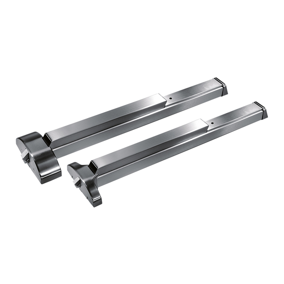
- Page 1 9000 Series MLR Motorized Latch Retraction Device Installation instructions 95071186 - 01-2021 | EN |...
-
Page 2: Table Of Contents
9000 Series MLR Installation Instructions Table of Contents Table of contents Installation ED Low Energy Operator Single Door Motorized Latch Retraction x Hard Wired Actuators x Input Device Single Door: F9300 MLR Exit Device x PS610RF Power Supply x ES105 Power Transfer x... -
Page 3: Installation
Specifications: Electrical input requirements: 24VDC + 10% filtered and regulated power supply; i.e. (DKPS-2A). (40PSU9000MLR- UK) The unit may also be powered by the dormakaba operator. Current: .88A max, inrush, 400mA max. hold Non polarized leads Provides simulatenous electric latch retraction and dogging (depressed touch bar) -
Page 4: Ed Low Energy Operator Single Door Motorized Latch Retraction X Hard Wired Actuators X Input Device
PARTS LIST: 1 EA. - ED J8 Low Energy Operator: 115 VAC +/- 10% 50/60 Hz, 6.6 Amp max. (DORMAKABA) 2 EA. - WS-1 Wall Actuator (DORMAKABA) 1 EA. - 9000 MLR Exit Device, .88 Amp @ 24VDC x Exterior trim (DORMAKABA) 1 EA. -
Page 5: Single Door: F9300 Mlr Exit Device X Ps610Rf Power Supply X Es105 Power Transfer
1 EA. - PS610RF Power Supply, Input: 115VAC/60 Hz, 0.8 Amps, Output: 1.0 Amps @ 24VDC, regulated and filtered (dormakaba) 1 EA. - F9300 MLR Exit Device, .88 Amp @ 24VDC x YP03 Pull Trim (dormakaba) 1 EA. - ES105 Power Transfer (dormakaba) 1 EA. -
Page 6: Field Troubleshooting Guide
Field Troubleshooting Guide Field troubleshooting guide dormakaba makes every effort to ensure all MLR units are adjusted properly and tested prior to shipping with units attached to the respective chassis assembly they will be used with, along with the proper power supply. -
Page 7: Field Troubleshooting Guide (Continued)
9000 Series MLR Installation Instructions Field Troubleshooting Guide Field troubleshooting guide (continued) Check to ensure door is prepared correctly to allow clearance for spindle and acutator H 1 1/2" Dia. x 1 3/4" High of trim to move freely. -
Page 8: Field Troubleshooting Guide (Continued)
9000 Series MLR Installation Instructions Field Troubleshooting Guide Field troubleshooting guide (continued) There are two seperate factory settings for the MLR units; the 9300 & 9700 require a different stroke setting than the 9400, 9800, 9100, 9600 or 9500. These are “preset at the factory”. The adjustment can be made in the field as a last resort if for some reason it should be required. -
Page 9: Mlr Spec Label
9000 Series MLR Installation Instructions MLR Spec Label MLR Spec label 2 " Specifications: Electrical input requirements: 24Vdc +10% Filtered and regulated power supply; ie: dormakaba 2" DKPS-2A. The unit may also be powered by the dormakaba ED900 operator. - Page 10 DORMA USA, Inc. T: 800-523-8483 www.dormakaba.us...
Need help?
Do you have a question about the 9000 Series and is the answer not in the manual?
Questions and answers