H3C MSR 20-20 Installation Manual
Msr 20 series routers
Hide thumbs
Also See for MSR 20-20:
- Command reference manual (2742 pages) ,
- User manual (60 pages) ,
- Supplementary manual (6 pages)
Table of Contents
Advertisement
Quick Links
Download this manual
See also:
User Manual
Advertisement
Table of Contents

Related Manuals for H3C MSR 20-20


Summary of Contents for H3C MSR 20-20
- Page 1 H3C MSR 20 Series Routers Installation Manual (v1.00) MSR 20-20 MSR 20-21 MSR 20-40 BOM: 3104A10S www.3Com.com Part Number: 10016319 Rev. AA August 2007...
- Page 2 LICENSE.TXT or !LICENSE.TXT. If you are unable to locate a copy, please contact 3Com and a copy will be provided to you.
-
Page 3: Get The Latest Documentation And Software For Your H3C Router
In addition to this Installation Guide, a detailed User Guide, Configuration Guide, and a Command Reference Guide are also available on the 3Com website. To obtain the most up-to-date user documentation and operating software for the MSR 20 Series router, point your web browser to: www.3Com.com and select... - Page 4 H3C R ET THE LATEST DOCUMENTATION AND SOFTWARE FOR YOUR OUTER...
-
Page 5: Table Of Contents
ONTENTS ET THE LATEST DOCUMENTATION AND SOFTWARE FOR YOUR H3C R OUTER BOUT UIDE Conventions Related Documentation VERVIEW Introduction Router Model and Structure Generic Modules NSTALLATION REPARATIONS NSTALLATION Installation Process Installing the Cabinet Installing the Router Installing Generic Modules Connecting the PGND Wire Connecting the Power Cord Connecting the Console Terminal Fixed Interfaces... - Page 6 Upgrading Application Program Through Ethernet Interface Maintaining Application Program and Configuration Through Command Lines Maintaining Application Program and Configuration File Dealing with Router Password Loss Backing up and Restoring BootROM ARDWARE AINTENANCE Preparing Tools Opening/Closing Chassis Cover Internal Structure Installing/Removing CF Card Replacing Memory Bar Installing/Removing ESM/VCPM Card ROUBLESHOOTING...
-
Page 7: Bout This Guide
(LAN) operations and familiarity with communication protocols that are used to interconnect LANs. Always download the release notes for your product from the 3Com World Wide Web site and check for the latest updates to software and product documentation: http://www.3Com.com... -
Page 8: Related Documentation
■ ■ ■ ■ These documents are available in Adobe Acrobat Reader Portable Document Format (PDF) on the CD-ROM that accompanies your router or on the 3Com World Wide Web site: http://www.3Com.com Description Italics are used to: Emphasize a point. -
Page 9: Overview
■ ■ Router Model and The H3C MSR 20 Series Routers include MSR 20-20, MSR 20-21, and MSR 20-40. Structure These three models are similar in chassis structure and layout. All of them can be put on the tabletop and can be mounted in 19-inch standard racks. The following subsections will give you more details about these three models. -
Page 10: Processor And Memory
1: O HAPTER VERVIEW Table 2 Interface card description of H3C MSR 20-20/20-21/20-40 Routers Item Internal module Processor and Memory Table 3 Processor and memory description of H3C MSR 20-20/20-21/20-40 Routers Item Processor BootROM Memory CF Flash BootROM stores bootstrap. ■... -
Page 11: Panel Leds
(7) Fixed Ethernet interface 1 (LAN1) (9) Auxiliary port (AUX) (11) CF card LED Panel LEDs The following table gives the features of H3C MSR 20-20 router LEDs: Table 5 Front panel LEDs description of MSR 20-20 router Description Power LED: ON means power is on. -
Page 12: Rear View
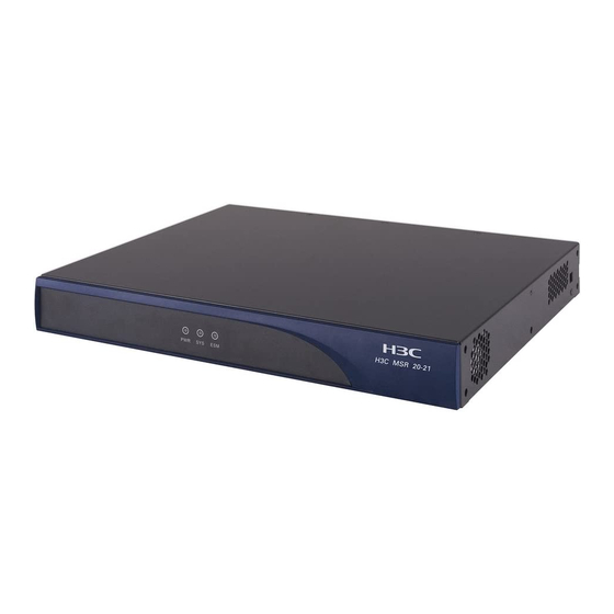
1: O HAPTER VERVIEW Table 5 Front panel LEDs description of MSR 20-20 router Table 6 Rear panel LEDs of H3C MSR 20-20 Router LINK H3C MSR 20-21 Router Appearance 1 Front view Figure 3 Front view of H3C MSR 20-21... - Page 13 (1) SIC slot2 (3) Grounding terminal (5) Power switch (7) Fixed Ethernet port1 (LAN1) (9) Auxiliary port (AUX) (11) CF card LED (13) Fixed L2 switching port (LAN2LAN9) Panel LEDs The following table gives the features of H3C MSR 20-21 router LEDs: Table 7 Front panel LEDs description of H3CMSR 20-21 router Description Power LED:...
- Page 14 1: O HAPTER VERVIEW H3C MSR 20-40 Router Appearance 1 Front view Figure 5 Front view of H3C MSR 20-40 (1) Power LED (POWER) (3) Console port (CONSOLE) (5) USB interface (7) CF card LED (9) Power switch 2 Rear view Figure 6 Rear view of H3C MSR 20-40 (1) FE interface 0 (3) SIC slot1...
-
Page 15: Generic Modules
Table 9 Front panel LEDs description of H3C MSR 20-40 router Table 10 Rear panel LEDs description of MSR 20-40 router LINK ESM0 to 1 VCPM VPM0 to 1 Generic Modules The MSR 20 series is available with generic modules such as SIC interface card and ESM. -
Page 16: Esm Module
1: O HAPTER VERVIEW ■ ESM Module ■ ■ ESM module supports IPSec and by using hardware encryption expedites IP packet encryption. The use of hardware encryption/decryption and hashing operation allows the router to encrypt packets with high performance and reliability. The encryption card is optional. -
Page 17: Requirements On Environment
NSTALLATION Requirements on H3C MSR 20 Series must be used indoors. To ensure the normal operation and Environment prolong their service life, the following requirements for installation site must be met. Requirements on To ensure the normal operation and prolong their service life, certain requirements Temperature/Humidity on temperature and humidity in the equipment room shall be met. -
Page 18: Requirements On Electrostatic Discharge Prevention
2: I HAPTER NSTALLATION REPARATIONS Table 14 Harmful limits in equipment room Requirements on Although many antistatic considerations have been given to H3C MSR 20 Series, Electrostatic Discharge damage to the router’s circuit or even the whole equipment may still happen when Prevention the static electricity exceeds the tolerance threshold. - Page 19 ■ ■ Checking the Rack When installing H3C MSR 20 Series Routers, observe the following: ■ ■ ■ ■ Safety Precautions Routers play a key role in data communications network. Please pay attention to the following: Warning: It indicates that this operation is incorrect and may seriously damage the router or endanger the operator.
- Page 20 2: I HAPTER NSTALLATION REPARATIONS Cables PGND wire and power cord ■ Console cable ■ Optional cables ■ Meters and equipment Hub or LAN switch ■ Console terminal (it could be a PC) ■ Equipment related to the selected modules ■...
-
Page 21: Installation Process
Installation Process Figure 7 H3C MSR 20 Series Router installation process NSTALLATION Start Mount the rack Connect PGND Connect the pow er cord Connect to the console terminal V erif y installation Pow er on Normal? Y E S Turn of f the pow er sw itch Install the FICs Install multifunctional... -
Page 22: Installing The Cabinet
Dimensions a Chassis H3C MSR 20 Series Routers are designed for mounting in a 19-inch standard rack and on the tabletop. The following table describes their dimensions: Table 15 H3C MSR 20-20/20-21/20-40 Router dimensions Router model MSR 20-20 MSR 20-21... - Page 23 Installing the Router Figure 8 Installing H3C MSR 20 Series Router in a rack (1) Mounting ear (2) Guide Figure 9 Installing ears on the rear panel of the H3C MSR 20-40 Series Router...
-
Page 24: Installing Generic Modules
3: I HAPTER NSTALLATION Installing Generic Installing generic modules includes installing the memory, ESM cards, and FICs. For Modules more information about the memory and ESM cards and their installation, refer to “Hardware Maintenance” on page 63 in this manual. For more information about FICs and their installation, refer to H3C MSR 20/30/50 Series Routers Interface Card and Interface Module Manual. -
Page 25: Connecting The Power Cord
Connecting the Power The MSR 20-20/20-21/20-40 router is available with AC-powered units. Cord Power Input and PGND Table 16 Power input and PGND of the MSR 20-20/20-21/20-40 router Item Power input PGND Connecting the AC-input AC power supply Power Cord... -
Page 26: Connecting The Console Terminal
3: I HAPTER NSTALLATION Connecting the Console port Console Terminal H3C MSR 20 series provides an RS232 asynchronous serial console (CON) port for router configuration, through which you can complete the configuration of the router. For its attributes, refer to Table 17: Table 17 Attributes of the console port Attribute Connector... -
Page 27: Fixed Interfaces
Fixed Interfaces Ethernet Interface Ethernet interface H3C MSR 20 Series Routers are available with fixed 100Base-TX FE interface(s) and Ethernet modules/cards for expansion. For more information, refer to H3C MSR 20/30/50 Series Routers Interface Card and Interface Module Manual. The following table describes Ethernet interface attributes. -
Page 28: Connecting The Ethernet Cable
3: I HAPTER NSTALLATION Connecting the Ethernet cable Follow the steps below to connect an Ethernet cable: Step 1: Connect one end of the Ethernet cable to an Ethernet port on the router and the other end to another device. For a 10/100 Mbps port provided by the RPU, connect it to a PC or another ■... -
Page 29: Aux Cable
devices, such as PC to PC or PC to router. You can make crossover cables yourself as needed. In making network cables, shielded cables are preferred for electromagnetic compatibility sake. Connecting the Ethernet cable Follow the steps below to connect an Ethernet cable: Step 1: Connect one end of the Ethernet cable to an Ethernet port on the router and the other end to another device. -
Page 30: Interface Card Module
3: I HAPTER NSTALLATION remote device. For the configuration procedures, refer to H3C MSR 20/30/50 Series Routers User Manual. Interface Card Module The MSR 20 Series Routers are available with various types of interface card modules. For detailed information refer to H3C MSR 20/30/50 Series Routers Interface Card and Interface Module Manual. -
Page 31: Verifying Installation
Uninstalling the Slide Figure 19 Loosen the screw Rail Figure 20 Draw out the slide rail Verifying Installation During router installation, you must verify installation each time you power on the router, making sure that: ■ ■ ■ ■ CAUTION: The check after installation is very important. The stability, grounding of the router and power supply will directly affect the operation of the router. - Page 32 3: I HAPTER NSTALLATION...
-
Page 33: Startup And Configuration
TARTUP AND ONFIGURATION Startup You can only configure the MSR 20 router through the console port if it is the first time you use it. Setting up Connecting the router to a console terminal Configuration To set up the local configuration environment, RJ-45 connector of the console Environment cable needs to be connected to the console port on the router, and DB-9 connector to the serial interface of a PC, as shown in the following figure. - Page 34 4: S HAPTER TARTUP AND ONFIGURATION shown in the following figure. Note that the selected serial interface should be consistent with the actual serial interface connected by the console cable. Figure 22 Setting the connection port in the local configuration 2 Setting terminal parameters.
- Page 35 terminal emulation type to be VT100 or auto detect, and click <OK> to return to the HyperTerminal window. Figure 24 Setting terminal type Powering on the Router Checking before power-on Check according to the following items before powering on the router. ■...
-
Page 36: Startup Process
4: S HAPTER TARTUP AND ONFIGURATION For local configuration, after you power on the router, you can see the startup banner. See “Startup Process” on page 36. 3 After completing the power-on self-test (POST), the system asks you to press <Enter>. -
Page 37: Configuration Fundamentals
Press Ctrl+B to enter extended boot menu... Enter <Ctrl+B>, the system will enter the extended BootROM menu; otherwise, the system will enter the program decompression process. The system enters the Boot extended menu only if <Ctrl+B> is pressed immediately (within six seconds) after the statement “Press Ctrl+B to enter extended Boot Menu...”... -
Page 38: Basic Configuration Procedures
4: S HAPTER TARTUP AND ONFIGURATION the WAN. For the dial-up interface, the user also needs to configure DCC parameters. Then, configure the link layer protocol encapsulated on the interface and the related operating parameters according to the WAN type. Step 4: Configure the IP addresses or IPX network numbers of all the interfaces on the router according to the division of the subnets. -
Page 39: Arranging Slots And Numbering Interfaces
The MSR 20 series provides many types of interfaces, such as console, AUX, Ethernet, serial (synchronous/asynchronous), and asynchronous port. The following describes how these interfaces are numbered. Figure 25 Slot arrangement on the MSR 20-20 (1) Slot0 Figure 26 Slot arrangement on the MSR 20-21... - Page 40 If you install an SIC-1FEA and an SIC-4FSW respectively in SLOT1 and SLOT2 on the AR MSR 20-20, the Ethernet interfaces are numbered as follows: Fixed Ethernet interfaces are Ethernet 0/0 and Ethernet 0/1;...
-
Page 41: Maintenance
Introduction Files BootROM program file The file is used for booting application at boot. A complete BootROM file includes two segments: basic and extended. Application program file The router is available with Dual Image function. By default, the system defines and attempts to boot in order with three boot files: main, backup, and secure, provided they are available with CF card. - Page 42 5: S HAPTER OFTWARE AINTENANCE By default, the system defines and attempts to boot in order with three configuration files: main, backup, and default, provided they are available with CF card. If the router fails to boot with the secure boot file, it prompts the boot failure.
-
Page 43: Software Maintenance
■ Software Maintenance ■ Methods ■ ■ ■ ■ Figure 28 Upgrade BootROM and Comware under Comware V5 environment BootROM Menu Main BootROM Menu When the router is powered on and reboots, the console terminal displays: The character “.” can be included in the file name, but cannot be the first or last character of the file name. - Page 44 5: S HAPTER OFTWARE AINTENANCE Do you want to go on checking sdram? Yes or not(Y/N) This prompts whether to perform memory check. Press <N/n> button to ignore it. The memory check function is developed for test. Since the test takes long ■...
-
Page 45: Bootrom Submenus
Please input Boot ROM password: You have three chances to provide the correct BootROM password (the initial setting is void). If you fail to do that, you need to reboot the system. After you enter the correct password, the console screen displays. ===================<EXTEND-BOOTROM MENU>===================== | <1>... - Page 46 5: S HAPTER OFTWARE AINTENANCE | <4> Update Secure Application File | <5> Modify Serial Interface Parameter | <6> Exit To Main Menu ============================================================= Enter your choice(1-6): The menu is defined as follows: Table 23 BootROM serial submenu Menu item <1>...
- Page 47 ========================<File CONTROL>======================= |Note:the operating device is CF Card | <1> Display All File | <2> Set Application File type | <3> Set Configuration File type | <4> Delete File | <5> Exit To Main Menu ============================================================= Enter your choice(1-5): The submenu is defined as follows: Table 25 File control submenu Menu item <1>...
-
Page 48: Upgrading Bootrom Through Serial Port
5: S HAPTER OFTWARE AINTENANCE Upgrading BootROM Use XModem to upgrade BootROM through serial port. Through Serial Port Modifying Serial Port Sometimes, we need to change the serial baud rate to higher in order to save Parameters upgrade time, or to lower to guarantee transmission reliability. This section depicts how to adjust serial baud rate. -
Page 49: Upgrading Bootrom
Upgrading BootROM Through Serial Port Figure 30 Modify baud rate Click [Call/Call] to establish new connection. Figure 31 Establish new connection Then, press <Enter> to prompt current configuration baud rate and return to the previous menu. The system prompts: The current baudrate is 115200 Restore the baud rate in the HyperTerminal to 9600 bps (the default) after upgrading the BootROM. - Page 50 5: S HAPTER OFTWARE AINTENANCE First, change serial baud rate to speed up upgrading (refer to “Modifying Serial Port Parameters” on page 48 “Modifying Serial Port Parameters” on page 48 for details), and then enter <3> under BootROM operation menu. The system prompts: Select program file please.
-
Page 51: Upgrading Application Program Through Serial Port
■ ■ ■ Upgrading Application Upgrading of application program through serial port is implemented under serial Program Through submenu. Enter <2> in the main BootROM menu to enter the serial submenu. Serial Port Refer to the “Enter serial submenu” on page 45 for detailed descriptions. For example, when you upgrade application program: First, change serial baud rate to speed up upgrading (refer to the “Upgrading BootROM Through Serial Port”... - Page 52 5: S HAPTER OFTWARE AINTENANCE inet on backplane (b): host inet (h) gateway inet (g) user (u) ftp password (pw) (blank = use rsh): 123456 FTP downloading password. No need flags (f) target name (tn) startup script (s) other (o) When configuring parameters, enter new parameters directly;...
- Page 53 Upgrading Application Program Through Ethernet Interface Connect Ethernet port 0/0 to a PC by using a crossover cable. Start TFTP/FTP program on the PC as the server, and set the path of TFTP/FTP server to point to the address of application program. You need to set user name and password if FTP server is used.
-
Page 54: Maintaining The Router With Tftp Server
5: S HAPTER OFTWARE AINTENANCE Enter the file control submenu and enter <2> to set the application file type. Please set application file type in cf: ******************************************************************** ******************************************************************** Enter File Name:cf:/main.bin Select the application program as the main boot file, and enter its complete path and file name. - Page 55 Maintaining Application Program and Configuration Through Command Lines Configuring environment Step 1: Set up hardware environment (refer to “Upgrading Application Program Through Ethernet Interface” on page 52 for details), and point the server path to the folder where the file is put. Figure 35 Networking diagram for maintenance under command line mode Console Ethernet...
- Page 56 5: S HAPTER OFTWARE AINTENANCE Deleting the old file, please wait... File will be transferred in binary mode Downloading file from remote tftp server, please wait...<HardReturn TFTP: File downloaded successfully. If a config.cfg file already exists in the router, select <Y/y> to overwrite it. CAUTION: ■...
- Page 57 Maintaining Application Program and Configuration Through Command Lines You can boot FTP service after configuring FTP server authentication and authorization. FTP server supports multi-user access. The remote FTP user sends request to the FTP server, which then executes accordingly and returns the result of the execution to user.
- Page 58 Step 2: Maintain the router through the terminal connected to the console port as follow: <H3C>ftp 192.168.0.1 Trying 192.168.0.1 ... Press CTRL+K to abort Connected to 192.168.0.1. 220 3Com 3CDaemon FTP Server Version 2.0 User(192.168.0.1:(none)): guest 331 User name ok, need password Password: 230 User logged in [ftp] Use the command as follows to maintain the router.
-
Page 59: Maintaining Application Program And Configuration File
FTP: 14323376 byte(s) sent in 15.974 second(s) 896.00Kbyte(s)/sec. [ftp]quit 221 Service closing control connection Maintaining You can modify and display the file type under the file control submenu: Application Program Enter <4> under the main BootROM menu to enter the file control submenu. The and Configuration File system prompts: ========================<File CONTROL>=======================... -
Page 60: Delete Files
5: S HAPTER OFTWARE AINTENANCE You can set the file type to +M, -M, +B and -B by entering 1 to 4. Refer to “Introduction” on page 41 for details. Set configuration file type Enter <3> under the file control submenu to enter the configuration file type menu. -
Page 61: Dealing With Router Password Loss
CAUTION: Confirm the file to be deleted before deleting since the system does not prompt you to confirm when deleting files. Exit to the main menu Exit to the main BootROM menu. Dealing with Router Do as follows when your BootROM password, user password or Super Password is Password Loss lost. -
Page 62: Backing Up And Restoring Bootrom
5: S HAPTER OFTWARE AINTENANCE BootROM Password Loss Contact the agent or our technical support personnel in the event of BootROM password loss. They can help you set a new password Modify the BootROM password under the main BootROM menu. Enter <5>... -
Page 63: Hardware Maintenance
Step 5: Drag the chassis levelly a little towards your body and lift it, and then you can remove the cover and put it away. Figure 38 Remove/install captive screws of MSR 20-20/20-21 ARDWARE AINTENANCE... - Page 64 6: H HAPTER ARDWARE AINTENANCE Figure 39 Turn the screwdriver in the hole on MSR 20-20/20-21 Figure 40 Remove/install captive screws of MSR 20-40 Figure 41 Turn the screwdriver on MSR 20-20/20-21 WARNING: On a mounting screw of your router chassis, there is an anti-dismantle seal of ■...
-
Page 65: Internal Structure
Internal Structure Figure 42 Internal structure of MSR 20-20/20-21 (1) Power module (3) ESM slot (5) SIC slot1 Figure 43 Internal structure of MSR 20-40 (1) Power module (3) SDRAM slot (5) ESM slot1 (7) Fan Internal Structure (2) Memory bar slot... -
Page 66: Installing/Removing Cf Card
6: H HAPTER ARDWARE AINTENANCE (9) VPM slot Installing/Removing CF Card Structure Figure 44 Front view of CF card Installing CF Card Install the CF card following these steps: Step 1: Push the spring button into the slot completely, and make sure it only springs out with outside force. -
Page 67: Replacing Memory Bar
Figure 46 Press the spring button to make the card spring out CAUTION: Do not remove the card when the router is booting or the LED is blinking to avoid hardware damage. Replacing Memory Bar This section describes how to replace a memory bar. See Figure 47. Figure 47 Memory bar maintenance flow Memory bars are main board components that you can expand or upgrade as needed. -
Page 68: Memory Bar Structure
6: H HAPTER ARDWARE AINTENANCE It is normal that you feel hard when removing the memory bar, but do not ■ overexert. Use the memory bars provided by Hangzhou H3C Technologies Co., Ltd. only. ■ Otherwise, anomalies might occur to the device Memory Bar Structure Figure 48 Memory bar structure Memory Bar Slot... -
Page 69: Installing/Removing Esm/Vcpm Card
Figure 50 Install memory bar into the slot Follow the steps below to remove the memory bar: Step 1: Make sure all power interfaces are shut down, and then proceed. Step 2: Press the spring clips on the two sides of the memory bar, and pull outwards levelly until the memory bar separates with the spring clips and forms an angle of 45 degrees with the main board. - Page 70 6: H HAPTER ARDWARE AINTENANCE Step 3: Install the card bracket on specified position on the main board, and fasten it on the board. Step 4: Align the card interface with the slot and press down vertically to install the card on the board. Then, align the screw eye with the card bracket. Step 5: Fasten the card on the bracket with dedicated screws, making sure the card is level and firm.
-
Page 71: Troubleshooting
Troubleshooting the Symptom: Power System The PWR LED on the PSU is OFF. Solution: Check that: ■ ■ ■ ■ Troubleshooting the If the router passes POST after powered on, the console screen displays the startup Configuration System banner; if faults occur to the configuration system, the console screen displays nothing or only illegible characters. -
Page 72: Troubleshooting Application Software Upgrade
7: T HAPTER ROUBLESHOOTING Stop bit: 1 Parity: None Flow control: None Terminal emulation: VT100 Reconfigure the parameters if their values are different. Troubleshooting Symptom 1: Application Software When upgrading the software using TFTP, the system displays: Upgrade boot device unit number processor number file name... - Page 73 Solution: Fault occurs because an incorrect application file is downloaded. Download the correct application program file. The bar code labels on the chassis and the FICs contain information about ■ production and servicing. Before you ask your agent for servicing, provide its bar code.
Need help?
Do you have a question about the MSR 20-20 and is the answer not in the manual?
Questions and answers