Table of Contents
Advertisement
Quick Links
Advertisement
Table of Contents

Related Manuals for Vimar By-alarm 01729


Summary of Contents for Vimar By-alarm 01729
- Page 1 Installer Manual By-alarm 01729 Two-way radio frequency interface SECURITY...
-
Page 3: Table Of Contents
By-alarm Table of Contents 1. Radio-frequency interface ……………………………………………………………………………………… 2 1.1 Main features of DSSS modulation ………………………………………………………………………… 2 1.2 Technical characteristics ……………………………………………………………………………………… 2 2. Installing the radio interface …………………………………………………………………………………… 3 2.1 Connection ……………………………………………………………………………………………………… 3 3. Radio devices ……………………………………………………………………………………………………… 4 4. Features of the radio interface ………………………………………………………………………………… 4 4.1 Amber control LED ……………………………………………………………………………………………... -
Page 4: Radio-Frequency Interface
By-alarm Radio frequency interface 1. Radio frequency interface The radio system is based on DSSS (Direct Sequence Spread Spectrum) modulation using various "codes"; the codes have been chosen so as to have a very low correlation with each other allowing the simultaneous transmis- sion of different systems guaranteeing correct operation. -
Page 5: Installing The Radio Interface
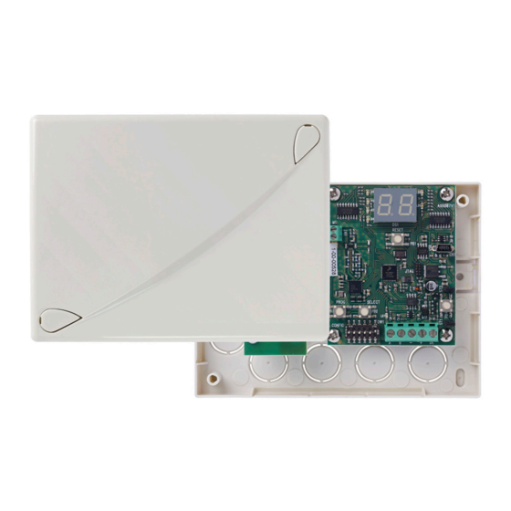
By-alarm Installing the radio interface 2. Installing the radio interface When securing the radio interface and to improve its operation, follow these instructions: • do not remove the circuits from the plastic enclosure. • do not install near metal objects and devices that generate radio frequencies (televisions, computers, routers, hot spots, etc.) •... -
Page 6: Radio Devices
By-alarm Radio devices - Radio interface features 3. Radio devices 01726: By-alarm curtain detector to protect entrances and openings such as doors, windows, covered terraces, corridors and French doors, 868 MHz radio frequency connection, surface mounting, powered by 1 lithium battery 3 V CR2477 (included). 01727.1: By-alarm magnetic RF contact + shock sensor, 868 MHz radio frequency connection, powered by 1 lithium battery 3 V CR123A (included). -
Page 7: Tamperproof Protection
By-alarm Features of the radio interface Flashing with a short pulse every second: - Correct power supply and serial communication. 4.2 Tamperproof protection The board has 2 push-buttons to protect against enclosure opening and against tearing it off the wall that can be excluded by closing the relevant jumpers under the push-buttons themselves. -
Page 8: Configuring The Radio Interface
By-alarm Configuring the radio interface The LEDs have the following meanings: - 1: Red LED -> tamper zone. - 2: Blue LED -> zone under supervision. - 3: Amber LED -> battery fault zone. - 4: Red LED -> zone in alarm status. - 5: Red LED ->... -
Page 9: Supervision
By-alarm Supervision Note: Take care to write down all the IDs assigned to the interfaces 01729 because later on, when configuring via the keypad or By-alarm Manager software, you will have to associate the same value. Depending on the ID assigned and the selection for the 8 or 16 radio Inputs, the control panel will assign 8 or 16 zones according to the numbering that depends on the presence of other interfaces 01729 and input expansion modules 01709- 01704 and the IDs assigned to them. -
Page 10: Signal Strength
By-alarm Signal strength - DIP-switches and display messages 7. Signal strength To check the strength of the radio signal of each single device during transmission, you can activate this specific function. a. Set the DIP-switches 1, 2 and 3 to ON and the display will show (signal). -
Page 11: Key To Display Messages
By-alarm Operations on radio frequency detectors 8.2 Key to display messages Address Delete Remote Controls Programming Supervision Signal strength detected Install contacts and detectors Install Remote Controls Delete Delete contacts and detectors Error 9. Operations on radio frequency detectors As explained above, the interface can have 8 or 16 radio inputs to be set during configuration; the relationship between these inputs and the alarm zones in the control panel depends on the addresses assigned to the inter- faces 01729 and any input expansion modules 01709 and 01704 that may be present. -
Page 12: Acquisition Of Art. 01727.1 And 01728
By-alarm Operations on radio frequency detectors 9.2 Acquisition of art. 01727.1 and 01728 Below is the general procedure for the acquisition of the detector 01727.1 (the procedure is similar for detectors 01728 since the push buttons to press have the same wording). Caution: Before acquiring the device, you need to set all its parameters as described in the respective instruction sheets (see instruction sheet for art. -
Page 13: Detector Art. 01728 With Separate Radio Channels
By-alarm Operations on radio frequency detectors - If the storage is successful, the interface display will show the subsequent free address that can be used for a new acquisition. - If the interface display shows the message repeat the detector channel configuration as described above. -
Page 14: Selective Deletion
By-alarm Operations on radio frequency detectors 9.4 Selective deletion a. Set the DIP-switch 1 to ON; the display will show (delete devices). b. Press the SELECT button and the display will show (All). c. Press the SELECT button to scroll through the devices installed in the system. d. -
Page 15: Operations On Remote Controls
By-alarm Operations on remote controls 10. Operations on remote controls 10.1 Saving: a. Set the DIP-switch 3 to ON and the display will show (Install Remote Controls). b. Press the SELECT button to scroll through the free addresses for remote control acquisition. c. -
Page 16: Total Deletion
By-alarm Operations on remote controls 10.4 Total deletion a. Set the DIP-switch 2 to ON; the display will show (Delete Remote Controls). b. Press the SELECT button and the display will show (All). c. Press the PROG button for total deletion, the display will show (delete). - Page 17 Viale Vicenza 14 36063 Marostica VI - Italy www.vimar.com 01729IEN 05 1907...
Need help?
Do you have a question about the By-alarm 01729 and is the answer not in the manual?
Questions and answers