Advertisement
Quick Links
Part number(s): HH
Part number(s): HHAU
Part number(s): HH/E01
Part number(s): HH/E02
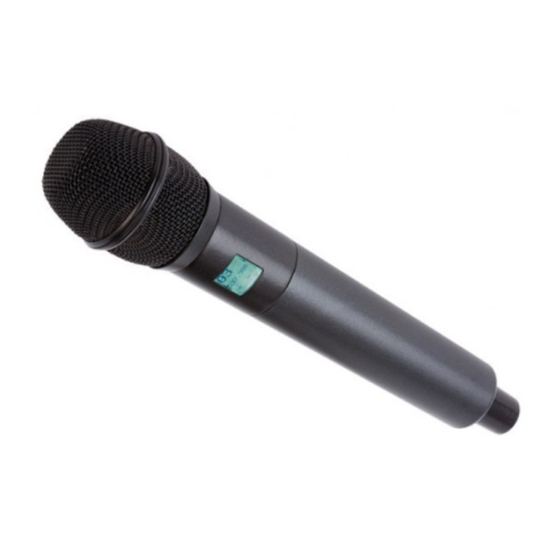
Common name: hand held transmitter Author(s):
04 Oct 2011
Date:
Initial setup: Audio Board only
Audio board with PIC18F67J11 µC IC
Step
Measurement name& description
Test Segment 10 of 60
Program µC IC and Current draw Audio board only
CAUTION
When reprograming already tested devices, be sure to set device programmer GUI to preserve all settings (block,
limiter settings, etc.). In Microchip MPLAB this is done by selecting Programmer > Settings > Program > Preserve
EEPROM on program > Apply > OK. Failure to do so will result in loss of all assigned variable values such as
frequency block, limiter setting, indicator settings, etc.
Note
This need only be performed at the factory the first time the DUT is powered up, when µC IC is replaced, or when a
firmware update is desired and confirmed to be appropriate.
Apply +3.0VDC, 300mA current limit in at battery contact J8 (J9 is circuit common)
In order to program DUT, JU1 must be jumpered or the power button must be pressed during the entire
Note
programming process. Remove JU1 jumper after programming.
Program µC IC with programming cable connected at J6 (ICSP port)
Remove ICSP cable
Measure current draw
Note
The goal here is only to ensure the audio board powers up and is not burning up with fever
Lectrosonics Standard Test & Alignment Procedure
Hardware version(s): 17424B (audio) & 17423B (radio) Firmware version(s):
Hardware version(s): 17424B (audio) & 17423B (radio) Firmware version(s):
Hardware version(s): 17424B (audio) & 17423B (radio) Firmware version(s):
Hardware version(s): 17424B (audio) & 17423B (radio) Firmware version(s):
Rodney Wildhagen & Cruz Garcia Test procedure version: 01.00
Measurement result (Typ)
50 to 500 mA
(117)
0.93
?
?
?
Advertisement

Subscribe to Our Youtube Channel
Related Manuals for Lectrosonics HH


Summary of Contents for Lectrosonics HH
- Page 1 Lectrosonics Standard Test & Alignment Procedure Part number(s): HH Hardware version(s): 17424B (audio) & 17423B (radio) Firmware version(s): 0.93 Part number(s): HHAU Hardware version(s): 17424B (audio) & 17423B (radio) Firmware version(s): Part number(s): HH/E01 Hardware version(s): 17424B (audio) & 17423B (radio) Firmware version(s): Part number(s): HH/E02 Hardware version(s): 17424B (audio) &...
- Page 2 Carrier power for various part numbers are as follows: part number connected to an untested radio board HH=100mW, HHAU & HH/E01=50mW and HH/E02 Test panel key pad or appropriate test rig connected to All audio measurements taken with a ≤ 10 Hz HPF and ...
- Page 3 Observe behavior of test audio board LCD "HH" "Vx.xx" "block XX" "Hybrid" frequency "Main" screen Note a flashing antenna icon inside a indicates the PLL is not locked Measure current draw 50 to 500 mA (145) Note The goal here is only to ensure the DUT powers up and is not burning up with fever...
- Page 4 and UP simultaneously will step the frequency up in increments of 16 only pressing the UP or DOWN buttons will only increment by 1) set channel (0(00) to 1020 (ff) in normal channel=XX tuning mode, 80 is 512) Adjust radio board C1 for 2.5 VDC at radio board TP1 (VCO_CONT) +2.45 to +2.55 VDC (+2.5) No DC power in at battery contacts...
- Page 5 16 to 17.5dBm 160 to 196 191 to 233 +14.8 to - mA (178) mA (212) HH/E01 18.8dBm HHB/E02 9.5 to 11.1dBm set transmitter power calibration parameter, "p" selects the power level must be 50 or 100, "s" specifies the...
- Page 6 NOTE: This segment may be performed using one known good pre-tested audio board to test multiple radio boards Spectral purity measurements and RF Mute function Prerequisite(s): FPGA IC programmed Connect RF Board J3(J4 common) DUT output to a splitter that feeds to the SpecAn, Frequency Counter high frequency input and the ModAn.
- Page 7 Momentarily connect audio board TP22 to J5 pin 4 (enter Set-up mode) Note Entering Set-up mode is not necessary if the Alternate Method is exercised. pilotbp=1 Using the test key pad navigate to the "DevOff" screen (Mid carrier freq is highlighted) tone=1 (sets DSP 1kHz test tone mode ON) Adjust radio board R26 for minimum modulation distortion at demodulated ≤...
- Page 8 Press BACK button on the test panel key pad to get back to the frequency "Main" screen tone=0 (turns off DSP 1kHz test tone) Test Segment 40 of 60 Install VCO shield cover No DC power in at battery contacts Disconnect radio board from audio board Install VCO shield assembly Part number ? Bend tabs at 45 degrees and Solder around the VCO shield...
- Page 9 LED's flash red once then green once Observe behavior of test key pad LCD "000000" "HH" "Vx.xx" "Hybrid" frequency "Main" screen a flashing antenna icon inside a indicates the PLL is not locked...
- Page 10 screen is displayed realtime button status bitmap (menu/sel=128, back=64, up=1, ok 0 (no buttons? down=2, "4=4", "3=8", "2=16", tolerance) "1=32", no button=0) Press and release control board Menu/Sel button Observe change in menu on LCD to the Menu screen press and hold realtime button status bitmap Menu/Sel (menu/sel=128, back=64, up=1,...
- Page 11 "1=32", no button=0) Release Up button Press and hold control board Back button Observe change in Menu on LCD return back to freq "main screen" realtime button status bitmap (menu/sel=128, back=64, up=1, ok 2 (no buttons? down=2, "4=4", "3=8", "2=16", tolerance) "1=32", no button=0) Release Back button...
- Page 12 mute=64) Release Mute button Press and hold control board Power button realtime button status bitmap (menu/sel=128, back=64, up=1, ok 0 (no buttons? down=2, "4=4", "3=8", "2=16", tolerance) "1=32", no button=0) Release Power button DC voltage measurements Apply +3.0VDC, 500mA current limit in at battery contact J8 (J9 is circuit common) Hold Power button for 3 seconds (make sure unit come on).
- Page 13 input Rig test point Audio board frequency block assignment Momentarily connect audio board TP5 to TP22 (enter Set-up mode) Note Entering Set-up mode is not necessary if the Alternate Method is exercised. Using the test key pad navigate to the "Block" screen. Press UP or DWN button on the test panel key pad to change unit to desired Block block= (set freq block 470,19-33, 944 standard 400-999 extended) Turn DUT Off then back On and check to see if the Block set.
- Page 14 Current draw tolerances procedure segment #20 for test procedure segment 50mW 100mW +16.3 to +19.3 to 50mW 100mW +17.7dBm +20.7dBm 333 to 414 to 17423 +16.3 to 407 mA 506 mA HHAU ≤ B +17.7dBm (370) (460) HH/E01 +14.8 to -...
- Page 15 18.8dBm HH/E02 9.7 to 11.1dBm set transmitter power calibration parameter, "p" selects the power level must be 50 or 100, "s" specifies the powercal(p,s)= position within the block and must be 0 for block bottom, 1 for block middle, or 2 for block top...
- Page 16 tuning mode, 80 is 512) BL944 specimens are permitted to exhibit 150% of otherwise allowable distortion. Some products have required this Note: additional margin. others have not. At the time of this writing, it is unknown how this product will shake out. Momentarily connect Audio Board TP5 to TP22 (enter Set-up mode).
- Page 17 Repeat this Section until no further adjustment is necessary. Press BACK button on the test key pad to get back to the main (frequency) screen. tone=0 (turns Off test tone) Low pass filter set / and Frequency adjust Prerequisite(s) Unit in set-up mode Unit at middle carrier frequency Note Entering Set-up mode is not necessary if the Alternate Method is exercised.
- Page 18 2.8 to 3.4 KHz (3.1) 1.5 to 1.9 KHz (1.9) Note Pilot Tone signal frequency at demodulated carrier at radio board J3 31.999 to 32.001 KHz (32) Noise measurements (low gain branch) Prerequisite(s) Unit in set-up mode Gain set to "0" Note Entering Set-up mode is not necessary if the Alternate Method is exercised.
- Page 19 gainsw=1 Measure Noise (noise signal amplitude) at radio board J3 ≤ -55dBu (-58) Tap edge of radio board repeatedly at corner opposite from power connections with ceramic screwdriver handle and measure noise at demodulated carrier at 0 to 18dB(r) (+5) radio board J3 referenced to step #40.100.10 value Using the test panel key pad navigate to the Gain screen and change audio gain to "Gain 45"...
- Page 20 level=0 (changes audio level to 0) Measure audio signal level at demodulated carrier at radio board J3 -43.5 to -41.5dB(r) (-42.5) Mute unit by pressing S1 mute=2 mute audio 1=unmuted 2=muted Measure audio signal level at demodulated carrier at radio board J3 ≤...
- Page 21 set channel (0(00) to 1020 (ff) channel=xx, ≤ 0.55% THD+N (0.35) in normal tuning mode, 80 is 512 Limiter range adjust / and -10 Limiter light adjust Prerequisite(s) Unit in set-up mode Note Entering Set-up mode is not necessary if the Alternate Method is exercised. DUT in "Passthru"...
- Page 22 Note: D5 typically switches from green to red with about -28 dBu +/- 1 dB applied to audio input rig Increase audio signal at DUT input amplitude by 10 dB Press the UP button the test panel key pad to set -10 LED limit10=0 (sets +10db limit LED threshold) If audio board D6 is red decrease 250 Hz signal at input rig by 2 dB and verify that audio board D6 switches to green, if so skip to next step...
- Page 23 of demodulated carrier (250Hz ref) at RF J3 10 kHz -1 to +1 dB(r) (-0.1) 1 kHz -1 to +1 dB(r) (-0.1) 50 Hz -1.5 to +1.5 dB(r) (+0.8) 31.5 Hz -5 to -1 db(r) (-3.1) -35 dBu, 250 Hz, low distortion, sinusoidal signal in at audio input rig Measure Phase responce of 20 kHz (-54)
- Page 24 demodulated carrier RF board Deviation Using the test panel key pad navigate to the "Gainsw" select high gain gainsw=1 (sets codec gain swith setting to X8 branch) Measure deviation at the 10.0 to 12.0kHz of demodulated carrier RF board (11) Deviation Measure distortion at the demodulated carrier RF board...
- Page 25 Note Entering Set-up mode is not necessary if the Alternate Method is exercised. DUT in "Passthru" Frequency set to middle Frequency set to middle frequency Gainsw set to auto gainsw=0 No audio signal at DUT input Apply +2.0VDC, 500mA current limit in at battery contact J8 (J9 is circuit common) Observe Battery Icon on LCD display battery icon blinking ON/OFF Using the test panel key pad navigate to the "BatMon"...
- Page 26 Carrier deviation and limiter distortion measurements (low gain) Prerequisite(s) Unit in set-up mode Note Entering Set-up mode is not necessary if the Alternate Method is exercised. DUT in "Passthru" Frequency set to middle frequency LF filter set to "LF 35" Using the test panel key pad navigate to the "Gain"...
- Page 27 0 to 5mA Audio input rig (single-ended audio signal source) The link ed image cannot be display ed. The file may hav e been mov ed, renamed, or deleted. Verify that the link points to the correct file and location. Lectrosonics, Inc.
Need help?
Do you have a question about the HH and is the answer not in the manual?
Questions and answers