
Summary of Contents for M&C SP2500-H Series
- Page 1 Gas sample probe Series SP ® SP2500-H, SP2500-H/C/I/BB, SP2500-H/C/I/BB/F Instruction Manual Version 1.00.02...
- Page 2 Dear customer, Thank you for buying our product. In this instruction manual you will find all necessary information about this M&C product. The information in the instruction manual is fast and easy to find, so you can start using your M&C product right after you have read the manual. If you have any question regarding the product or the application, please don’t hesitate to contact M&C or your M&C authorized distributor.
-
Page 3: Table Of Contents
Contents General information ........................4 Declaration of conformity ......................4 Safety instructions........................5 Warranty ............................5 Used terms and signal indications .................... 6 Introduction ..........................8 Description ..........................8 Options ..........................11 Technical data ........................... 12 Dimensions ..........................13 10 Receipt and storage ........................13 11 Installation information ...................... -
Page 4: General Information
Head Office M&C TechGroup Germany GmbH Rehhecke 79 40885 Ratingen Germany Telephone: 02102 / 935 - 0 Fax: 02102 / 935 - 111 E - mail: info@mc-techgroup.com www.mc-techgroup.com GENERAL INFORMATION The product described in this instruction manual has been examined before delivery and left our works in perfect condition related to safety regulations. -
Page 5: Safety Instructions
SAFETY INSTRUCTIONS Follow these safety directions and instructions regarding installation, commissioning and op- eration of this equipment: Read this instruction manual before starting up and use of the equipment. The information and warnings given in this instruction manual must be heeded. Any work on electrical equipment is only to be carried out by trained specialists as per the regulations currently in force. -
Page 6: Used Terms And Signal Indications
USED TERMS AND SIGNAL INDICATIONS This means that death, severe physical injuries and/or important material damages will occur in case the respective safety measures are not fulfilled. Danger This means that death, severe physical injuries and/or important material damages may occur in case the respective safety measures are not fulfilled. - Page 7 Wear protective gloves! Working with chemicals, sharp objects or extremely high temperatures requires wearing protective gloves. Wear safety glasses! Protect your eyes while working with chemicals or sharp objects. Wear safety glasses to avoid getting something in your eyes. Wear protective clothes! Working with chemicals, sharp objects or extremely high temperatures requires wearing protective clothes.
-
Page 8: Introduction
INTRODUCTION M&C SP2500-H.. series probes are used for continuous gas sampling in dust-loaded processes at high temperatures and high gas moisture. The probe offers the possibility to remove the preliminary filter or sample tube in the process without having to remove the probe head for cleaning purposes. H/C/I/BB and ..-H/C/I/BB/F series probes are used in highly dust-loaded processes. -
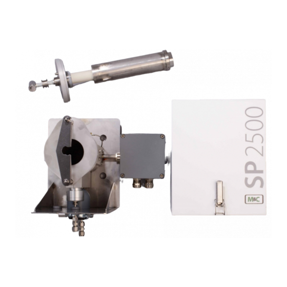
Page 9: Figure 1 Probe Type Sp2500-H
The filter element, and via this indirectly, the filter space and sample tube or preliminary filter can • be backflushed via the check valve /BB/F installed in the heated chamber wall. The following figures show the probe types SP2500-H, ...H/C/I/BB, ...H/C/I/BB/F. Option: C Pre-filter To >+30°C... -
Page 10: Figure 3 Probe Type Sp2500-H/C/I/Bb/F
Pre-filter To >+30°C Tref. 0- 180°C Tu < - 30°C 3 4 5 N L ' L Sample tube Power Low temperature 230V,50Hz alarm (115V,60Hz) Tube 8x1 Tube 6x1 1/4" NPTi 1/8" NPTi Backflush Control Test gas 2-6bar 3-10bar >0,7bar Backflush Test gas Sample... -
Page 11: Options
OPTIONS The following list shows the options available. The diversity of options and modular design of M&C gas sample probes ensure optimum probe selection to suit the particular process and ambient conditions. Description Part No. Basic typeSP2500H, heated to 0 - 180 °C, with weatherproof cover, 20S3510 Material stainless steel 316Ti Basic type SP2500-H/C/I/BB, heated to 180 °C, with weatherproof cover,... -
Page 12: Technical Data
TECHNICAL DATA SP ® series SP2500-H SP2500-H/C/I/BB SP2500-H/C/I/BB/F Technical data Part No. 20S3510 20S3520 20S3530 Integrated backpurging Via filter space Via filter element Weatherproof cover Electrical connection Terminals; max. 4 mm², 2 x PG13.5 cable gland Degree of protection of terminal IP 54 EN 60529 Power supply 230 V 50/60 Hz, 800 W or 115 V 60 Hz, 800 W (fuse 10 A) -
Page 13: Dimensions
DIMENSIONS The following illustration shows the dimensions of the SP2500-H.. probe. To >+30°C Tref. 0- 180°C Tu < - 30°C 3 4 5 N L ' L Figure 4 Dimensions (mm) of SP2500-H.. probe RECEIPT AND STORAGE • The probe and any special accessories should immediately be unpacked carefully upon delivery and against the delivery note. -
Page 14: Installation Information
INSTALLATION INFORMATION When carrying out installation, the safety rules and regulations for the prevention of accidents must be observed – this applies similarly to subsequent operation. The information in Chapter 3 “Important safety information” must be observed in particular. The following applies: Select an optimal sample point according to the general guidelines or agree on a sample point with •... -
Page 15: Installation
INSTALLATION M&C SP2500-H.. probes are designed for stationary use and with correct selection of the sample point and proper installation, they will give many years of trouble-free service with minimum maintenance. 12.1 PROBE ASSEMBLY Remove the probe cover after opening the two toggle-type fasteners. •... -
Page 16: Fitting Preliminary Filter Or Sample Tube
12.2 FITTING PRELIMINARY FILTER OR SAMPLE TUBE The SP2500-H.. probe offers the possibility of fitting or removing the preliminary filter or sample tube in the process without having to remove the probe head. For this purpose, the filter housing covers must be removed as follows: Figure 5 Schematic diagram of filter housing cover Turn handle A about one full turn anticlockwise, so that the cover is lifted. -
Page 17: Figure 6 Removal Of Filter Housing Cover
The following figures show the described steps. Figure 6 Removal of filter housing cover Fitting of the preliminary filter or sample tube takes place as follows: • Unscrew the mounting adapter for the preliminary filter or sample tube from the filter housing cover . -
Page 18: Connection Of Sample Line
Check that the filter element is screwed tight and then screw on the mounting adapter again. • Screw the preliminary filter or sample tube with appropriate seal into the ¾“ thread of the mounting • adapter ; • Push the filter housing cover with preliminary filter or sample tube into the filter space ... -
Page 19: Connection Of Backpurging And Calibration Gas Line
12.4 CONNECTION OF BACKPURGING AND CALIBRATION GAS LINE The backpurging pressure must be higher than the process pressure. Attention Pay attention to the maximum pressure level (see technical data). SP2500-H: For option “C”, a check valve is fitted (see Figure 1, opening pressure 0.7 bar). Connection of the backpurging or calibration gas line takes place on the underside of the probe. -
Page 20: 12.5.1 Versions With Internal Capillary Tube Thermostat
12.5.1 VERSIONS WITH INTERNAL CAPILLARY TUBE THERMOSTAT Remove the connection box cover. The electrical wiring • diagram shown is contained in the cover. Insert the mains cable (min. 3 x 1.5 mm ) through the • cable gland and connect to the appropriate terminals. •... -
Page 21: Starting
STARTING Prior to starting the device, the system and process-specific safety measures must be observed. For the media to be supplied, the relevant safety requirements and measures must be taken into account. Prior to starting the device, it must be verified that the system voltage corresponds with the voltage shown on the rating plate! Warning If the set temperature on the capillary controller should be reduced in one... -
Page 22: Closing Down
CLOSING DOWN Prior to closing down, i.e. switching off the heating, the probe should be flushed with inter gas or air in order to prevent the condensation of aggressive components from the process gas. MAINTENANCE Prior to carrying out maintenance and repairs, the system and process-specific safety measures must be observed. -
Page 23: Replacement Of Filter Element And Seals
15.1 REPLACEMENT OF FILTER ELEMENT AND SEALS Prior to carrying out maintenance and repairs, it must be ensured that no health-endangering contaminants remain in the probe. An appropriate measure is to flush the probe with inert gas, for example. Warning Before replacing the filter element, the sample gas supply must be interrupted! For replacement of the filter element or seals, the following procedure is recommended:... -
Page 24: Spare Parts List
SPARE PARTS LIST The wearing and spare parts required depend on the specific operating conditions. The following table contains some recommended spare parts for SP2500-H/.. . series probes Recommended spare part Part No. Description 90S0020 Spare filter element S-2K150, ceramic, 2 µm, 150 mm 93S0045 Spare gasket (30), Viton , for filter element S-2K150...
Need help?
Do you have a question about the SP2500-H Series and is the answer not in the manual?
Questions and answers