Table of Contents
Advertisement
Quick Links
Advertisement
Table of Contents

Related Manuals for Tektronix P5102


Summary of Contents for Tektronix P5102
- Page 1 P5102 100 MHz High-Voltage Probe Instructions 070-9294-01...
- Page 2 Copyright Tektronix, Inc. 1995. All rights reserved. Tektronix products are covered by U.S. and foreign patents, issued and pending. Information in this publication supercedes that in all previously published material. Specifications and price change privileges reserved. Printed in the U.S.A.
-
Page 3: Table Of Contents
........Replaceable Parts ........P5102 Instructions... - Page 4 ......Figure 14: P5102 Replaceable Parts .....
-
Page 5: General Safety Summary
Do Not Immerse in Liquids. Clean the probe using only a damp cloth. Refer to cleaning instructions on page 15. Safety Terms and Symbols Terms in This Manual. These terms may appear in this manual: P5102 Instructions... - Page 6 Category and Safety Class. Overvoltage Category. Overvoltage categories are defined as follows: CAT III: Distribution level mains, fixed installation CAT II: Local level mains, appliances, portable equipment CAT I: Signal level, special equipment or parts of equipment, telecommunication, electronics P5102 Instructions...
-
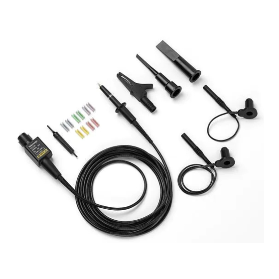
Page 7: Features And Accessories
Features and Accessories The P5102 is a high-voltage passive probe designed for use with TekScope THS 700 series instruments. The probe features a floating common and is ideal for measuring and troubleshooting power supplies and high-voltage devices. The probe provides 10X... - Page 8 Features and Accessories P5102 Features and Standard Accessories (Cont.) Compensation Box – The compensation box contains low- and high-frequency compensation adjustments. The high-frequency adjust- ments are accessible by removing the compensation box cover. Refer to Adjustments on page 7. Adjustment Tool –...
- Page 9 The hook tip will firmly hold the conductor under test. Common Leads – The P5102 probe comes with a long and a short floating common lead. Both common leads connect to a removable crocodile clip.
- Page 10 Features and Accessories P5102 Optional Accessories Probe Tip Extender (P6000) – Use the probe tip extender to con- nect the probe to larger test sockets located in equipment or on printed circuit boards. Connect the probe tip extender by screwing it onto the threaded probe tip.
-
Page 11: Operating Basics
Operating Basics To get guaranteed performance from the P5102 probe, please read and apply the information in this section. Observe Voltage Derating Information WARNING. To avoid personal injury, do not handle the probe when the common lead is connected to a source that is above the voltage and frequency limits given in Figure 11b on page 18. -
Page 12: Probe Loading
Refer to Figure 12 on page 19 for a graph of frequency versus input impedance. The probe has virtually no loading effect on sources with relatively low impedance and low frequency. P5102 Instructions... -
Page 13: Adjustment Procedures
Adjustment Procedures The low-frequency (LF) compensation of the P5102 probe must be checked every time the probe is connected to a different oscilloscope input. The high-frequency (HF) compensation should be checked if the probe was repaired or fails to meet rated bandwidth specifications. -
Page 14: Hf Compensation
<1 ns 1 MHz 1 Vpp Figure 5: Signal Source Characteristics for HF Compensation To access the HF adjustments of the probe, you must open the cover of the compensation box using the procedure that follows. P5102 Instructions... -
Page 15: Figure 6: Opening The Compensation Box
1. Insert the flat blade of small screwdriver (A) into the location shown in Figure 6. Insert the blade until it stops against the back of the tab. Insert up to the Tab Figure 6: Opening the Compensation Box P5102 Instructions... -
Page 16: Figure 7: Hf Compensation Setup
Generator FAST RISE Output Terminator Probe-to-BNC Adapter P5102 Probe Figure 7: HF Compensation Setup 2. Refer to page 4 and use the optional probe-to-BNC adapter to connect the probe to the termination. 3. Set the Calibration Generator to 1 MHz. -
Page 17: Figure 8: Hf Compensation Adjustments
9. Preset HF1 counterclockwise and HF2 clockwise. 10. Adjust HF2 for flatness and adjust HF1 for the best front corner. See Figure 9. Because HF1 and HF2 interact, readjust HF2 and HF1 as necessary to achieve the best rise time with the smallest aberrations. P5102 Instructions... -
Page 18: Figure 9: Hf Compensation Regions Of Fast Rise Signal
Adjustment Procedures (20 ns) (10 ns) Aberrations Figure 9: HF Compensation Regions of Fast Rise Signal 11. After compensating the HF, carefully slide the cover back until the tab latches securely into place. P5102 Instructions... -
Page 19: Performance Verification
Performance Verification Use the procedure in this section to verify that the P5102 probe meets the warranted bandwidth specification highlighted with boldface type in the Specifications section on page 17. The steps of this procedure must be performed in the order given using a THS 720 TekScope instrument and other equipment that meets the minimum requirements listed in Table 1. -
Page 20: Figure 10: Bandwidth Test Setup
Performance Verification 1. Connect the test setup as shown in Figure 10. Leveled Sine Wave Generator Terminator P5102 Probe Test Oscilloscope Probe Tip to Output BNC Adapter Figure 10: Bandwidth Test Setup 2. Set the leveled signal generator output frequency to 1 MHz. -
Page 21: Maintenance
Maintenance This section contains information necessary for the maintenance and repair of the P5102 probe. NOTE. The P5102 probe has no replaceable components. Accessory parts may be ordered as indicated in the replaceable parts list. Cleaning Instructions Clean the probe using a soft cloth dampened with a mild detergent and water solution. -
Page 22: Preparation For Shipment
2. Put the probe into a plastic bag or wrap to protect it from dampness in transit. 3. Place the probe into the box and stabilize it with light packing material. 4. Seal the carton with shipping tape. P5102 Instructions... -
Page 23: Specifications
Specifications that are not warranted are typical (Tables 3 and 4) and are provided as general information for your convenience. The specifications apply to a P5102 probe installed on a Tektronix THS 720 oscilloscope. The instrument must have a warm-up period of at least 10 minutes and be in an environment that does not exceed the limits described in Table 5. -
Page 24: Figure 11: Maximum Voltage Derating Curves
Category I & II maximum voltage limit 500V RF burn risk area (shaded) Category III maximum voltage limit Voltage 100V DC or 0 100k 500k 100M Frequency (Hz) Figure 11: Maximum Voltage Derating Curves (V , DC Coupled) P5102 Instructions... -
Page 25: Figure 12: Typical Input Impedance
Input Capacitance (System) 11.2 pF Probe connected to instrument and properly compensated. Checked at 1 MHz 10 M 100 k 10 k DC or 0 10 k 100 k 10 M 100 M Frequency (Hz) Figure 12: Typical Input Impedance P5102 Instructions... -
Page 26: Figure 13: Typical Input Phase
Specifications DC or 0 10 k 100 k 10 M 100 M Frequency (Hz) Figure 13: Typical Input Phase P5102 Instructions... -
Page 27: Table 4: Typical Mechanical Characteristics
Five cycles (120 hr. total) at 95% to 97% relative humidity This environmental exposure is more severe than that stated in MIL-T-28800E for Class 3 Equipment Transportation Qualified under the National Safe Transit Association’s Preshipment Test Procedures, Project 1A-B P5102 Instructions... -
Page 28: Replaceable Parts
Replaceable Parts Standard Accessories Optional Accessories Figure 14: P5102 Replaceable Parts P5102 Instructions... - Page 29 Replaceable Parts P5102 Instructions...
- Page 30 Replaceable Parts P5102 Instructions...
- Page 31 Tektronix, shipping charges prepaid, and with a copy of customer proof of purchase. Tektronix shall pay for the return of the product to Customer if the shipment is to a location within the country in which the Tektronix service center is located.
Need help?
Do you have a question about the P5102 and is the answer not in the manual?
Questions and answers