Table of Contents
Advertisement
Quick Links
Advertisement
Table of Contents

Related Manuals for Xylem YSI H-3553T


Summary of Contents for Xylem YSI H-3553T
- Page 1 OWNERS MANUAL V2.3 H-3553T BUBBLER / PRESSURE SENSOR D44-02 0615...
-
Page 2: Table Of Contents
CONTENTS & WARRANTY This user manual is a guide for the H-3553T. For more information, updated manuals, brochures, technical notes, and supporting software on the H-3553T please refer to waterlog.com/3553 or contact your sales representative. For additional assistance, please contact us at +1.435.753.2212 or sales@waterlog.com WaterLOG®... -
Page 3: Waterlog® Warranty
Contents & Warranty “WATERLOG™ PRODUCTS MANUFACTURED BY YELLOW SPRINGS INSTRUMENTS CO., INC. are warranted by Yellow Springs Instruments Co., Inc. (“YSI”) to be free from defects in materials and workmanship under normal use and service for twelve (12) months from date of shipment unless otherwise specified in the corresponding YSI pricelist or product manual. -
Page 4: Chapter 1: Introduction
01 / INTRODUCTION... -
Page 5: Bubbler Features
Introduction The WaterLOG® H-3553T/ Pressure Sensor is well known for its compact size and combination of a Bubbler and built-in pressure sensor. The H-3553T has also been referred to as a self-contained “smart” gas purge system, because it produces a precision constant mass flow of gas. Designed to measure fluid levels in surface water, ground water and tanks, the H-3553T Modbus or Auto mode is enabled it will enter the RS-232 menu with any character sent to this port. -
Page 6: Chapter 2: Getting Started
02 / GETTING STARTED... -
Page 7: What's In The Box
Getting Started Before installation, setup and operation of the H-3553T in the field, read through this section for a general overview of what you have and how to use it. What’s in the Box When unpacking your H-3553T, make sure all the components ordered are received and undamaged from shipping. -
Page 8: Product Description
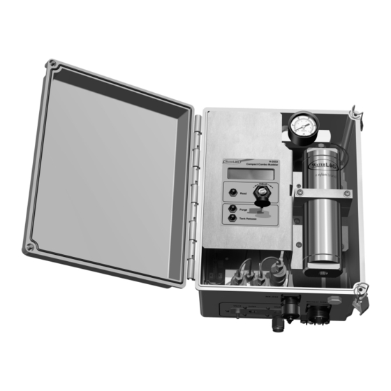
GETTING STARTED Product Description It is important to familiarize yourself with the connections before installing a product at the site. Below are standard connections found on the H-3553T. Enclosure Breather RS-232 Menu Setup Port & Cable Connection Power & Communications Main Interface Connection Atmospheric PSI Vent for Sensors Compressor Air Intake Desiccator Connection Constant Bubble Out Orifice Line Connection 1/8 inch FNPT... -
Page 9: Using The Display
Getting Started Using the Display Table 2-1: Main I/O Sensor Interface Cable Colors Signal Cable/Bulkhead The H-3553Ts display has a ‘Read’ button that when pressed will cause the unit to initiate a new +12 VDC measurement and update the display. Measurement Black requests from an attached SDI-12 data logger will Yellow... -
Page 10: Chapter 3: Installation
03 / INSTALLATION... -
Page 11: Water Depth
Installation The WaterLOG® H-3553T is a system with a fully integrated digital pressure transducer specifically designed for water level monitoring. The H-3553T directly measures dry gas over a broad temperature range. WARNING! Before proceeding with the installation, please consider the following site preparation steps to help prevent problems later. -
Page 12: Power Wiring
GETTING STARTED the line not related to the water depth. The line should be installed in an area where the flow of water will remain relatively calm as compared to the real stage changes. Here are a few Do’s and Do not’s on mounting the line. -
Page 13: Chapter 4: Setup & Operation
04 / SETUP & OPERATION... -
Page 14: Rs-232 Menu
SETUP & OPERATION There are three ways to setup and operate the H-3553T, through the RS-232 menu interface, the SDI-12 interface, and through the XL series DCP menu interface. Setup through the XL series DCP menu is not discussed in this manual but is discussed in the XL series manual. This chapter will focus on setup using the RS-232 menu interface and the SDI-12 interface. - Page 15 Setup & Operation SDI-12 Interface The SDI-12 interface is another way to setup and operate the H-3553T. The H-3553T supports all standard SDI-12 commands and uses some SDI-12 extended (manufacturer specific) commands for setup operation. SDI-12 standard and extended commands are normally sent from a SDI-12 master device, like the Waterlog XL series DCP.
-
Page 16: Sdi-12 Interface
SETUP & OPERATION Default Setup The H-3553T has many settings that can be change. However, the default setups will normally cover most applications. Table 4-3 shows the default settings for the H-3553T. Table 4-3: H-3553T Default Setup Setting Default Setting Setting Range SDI-12 Address 0-9 (Standard), A-Z, a-z... -
Page 17: Sdi-12
Setup & Operation SDI-12 The SDI-12 address of a sensor is its identifier on the SDI-12 data bus. The SDI-12 data bus is a one wire communication between normally one master device and one or more slave devices. The SDI-12 address makes it possible for the master device to communicate with each sensor individually. -
Page 18: Set Current Stage
SETUP & OPERATION Note Table 4-7, the ‘a’ is the current SDI-12 address of the H-3553T and the ‘xxxx’/’x.xxx’ is the current units/ slope of the H-3553T and the ‘nnnn’/’n.nnn’ is the desired new units/slope. Table 4-7: Change the H-3553T Units / Slope H-3553T Combo Bubbler Setup Menu SDI-12 Interface U - Units: xxxx... -
Page 19: Stage Offset
Setup & Operation Stage Offset The stage offset is a value that is added to the final stage result after the slope/multiplier has been applied. The stage offset is normally used to obtain a final stage level relative to some reference point such as sea level. Writing the stage offset is not needed when using the set current stage option, because this option calculates and sets the stage offset automatically. -
Page 20: Rs-232 Stage Digits
SETUP & OPERATION Note: This averaging time does not take into account the time it takes to make an atmospheric reading. Therefore, always add about 4 more seconds to the averaging time to calculate how long the full measurement cycle can take. Table 4-10: Change the H-3553T Stage Averaging Time H-3553T Combo Bubbler Setup Menu SDI-12 Interface... -
Page 21: Bubble Rate
Setup & Operation Bubble Rate The bubble rate is the average number of bubbles flowing Table 4-12: Bubble Rate vs. Response Time from the end of the orifice line per minute. The standard Bubble Rate Response for 1 Ft. Rise orifice line tubing that we recommend and calibrate the 30 bubbles/min 25 seconds... -
Page 22: Purge
SETUP & OPERATION Purge The H-3553T has an option built in called purge, the purpose of the purge is to clear out any debris or silt from the end of the orifice line that could cause false pressure readings. When a purge is initiated the H-3553T makes a new measurement on the line and tank sensor and saves the values away just in case data is requested during the purge. -
Page 23: Purge Sustain
Setup & Operation ‘B’ key to enter the “Bubbler Settings” menu and then press the ‘P’ key, then enter in the desired purge pressure and press the ‘Enter’ key. To change the H-3553T purge pressure using the SDI-12 interface, send the “aXWPPnn!” SDI-12 extended command. -
Page 24: 4-20 Milliamp Output
SETUP & OPERATION Table 4-16: Change the H-3553T Purge Sustain H-3553T Combo Bubbler Setup Menu SDI-12 Interface B – Bubbler Settings Command: aXWPSnn! Response: a0061 Bubbler Settings Menu Command: aXRPS! S – Purge Sustain: xx Response: a0021 Enter Purge Sustain (10 - 40) [ nn ] Command: aD0! Response: a + nn 4-20 Milliamp Output... -
Page 25: 4-20 Milliamp Max Stage
Setup & Operation Table 4-17: Change the H-3553T 4-20 Milliamp Min Stage H-3553T Combo Bubbler Setup Menu SDI-12 Interface P – Advanced Options Command: aXWILn.nn! Response: a0021 Advanced Options Menu Command: aXRIL! F – 4-20 mA Output Response: a0011 Command: aD0! 4-20 mA Output Setup Menu Response: a + n.nn N –... -
Page 26: Modbus Mode Enable
SETUP & OPERATION Modbus Mode Enable The Modbus mode enable is the setting that determines whether the H-3553T will communicate with a Modbus master device. Modbus is an industry standard serial digital interface for interconnecting Programmable Logic Controllers (PLCs), intelligent sensors and other devices. The H-3553T can be used as a Modbus slave and has a serial RS-485 port for connecting to a Modbus compatible host device. -
Page 27: Measure Rate (Auto Mode Enabled)
Setup & Operation RS-232 main menu, press the ‘P’ key to enter the “Advanced Options” menu. Then under the “Measurement Options” section press the ‘A’ key and the Auto mode enable will change to on. To change the H-3553T Auto mode enable using the SDI-12 interface, send the “aXWAE1!” SDI-12 extended command to enable or change the ‘1’... -
Page 28: Test Display
SETUP & OPERATION Table 4-21: Change the H-3553T Measure Rate H-3553T Combo Bubbler Setup Menu SDI-12 Interface P – Advanced Options Command: aXWMRnnn! Response: a0021 Advanced Options Menu Command: aXRMR! R - Measure Rate: xx Response: a0021 Enter Measure Rate (0 - 255) [nnn ] Command: aD0! Response: a + nnn Test Display... -
Page 29: Chapter 5: Modbus Operation
05 / MODBUS OPERATION... -
Page 30: Communication Setup
MODBUS OPERATION The H-3553T supports a Modbus client protocol interface. Modbus is an industry standard field bus for interconnecting Programmable Logic Controllers (PLCs), intelligent sensors and other devices. The H-3553T communicates Modbus via the RS-485 serial port connections; see Chapter 2 Table 2-1 for wiring connections. This chapter will focus on Modbus setup and operation using the RS-232 menu interface or the SDI-12 interface. -
Page 31: Id String Registers
Modbus Operation Stage Offset 25 / “0019” 32 Bit Float Stage Slope 27 / “001B” 32 Bit Float *Stage 29 / “001D” 32 Bit Float *Pressure 31 / “001F” 32 Bit Float *Temperature 33 / “0021” 32 Bit Float *Control Battery 35/“0023”... -
Page 32: Baudrate Select Registers
MODBUS OPERATION Baudrate Select Registers The Baudrate holding register allows the user to change Table 5-5: Baud Rate Select Register Options the baud rate of the Modbus RS-485 serial port. Table Register Value Stage Units 5-5 shows what the Modbus baudrate holding register 9600 (Default) should be set to get the desired baudrate. -
Page 33: Stage Slope Register
Modbus Operation Stage Slope Register The Stage Slope holding register allows the user to enter a user defined stage slope. Writing to this register is only applicable when the Stage Units Select Register is set to 06, which indicates the user defined mode for the units. - Page 34 MODBUS OPERATION Example #2: Write Multiple Registers Command: Format: “aabbccccddddeeffffgggg” Where: aa = 1 byte Modbus address bb = 1 byte function code cccc = 2 byte start address dddd = 2 byte quantity of registers ee = byte count ffff = 2 byte data value gggg = 2 byte crc value Example: 011000010001022000BE41...
- Page 35 This user manual is a guide for the H-3553T. For more information, updated manuals, brochures, technical notes, and supporting software on the H-3553T please refer to waterlog.com/3553 or contact your sales representative. For additional assistance, please contact us at +1.435.753.2212 or sales@waterlog.com...
- Page 36 150 countries, we have strong, long-standing relationships with customers who know us for our powerful combination of leading product brands and applications expertise, backed by a legacy of innovation. For more information on how Xylem can help you, go to www.xyleminc.com YSI Incorporated 1700/1725 Brannum Lane...
Need help?
Do you have a question about the YSI H-3553T and is the answer not in the manual?
Questions and answers