
Related Manuals for Miller RFCS-5


Summary of Contents for Miller RFCS-5
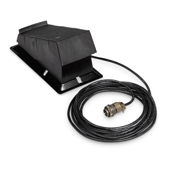
- Page 1 OM-844 183 973G 6/2004 Foot Controls RFCS-5, RFCS-5HD, RFCS-6M, RFCS-14, And RFCS-14HD Visit our website at www.MillerWelds.com...
- Page 2 We know you don’t have time to do it any other way. That’s why when Niels Miller first started building arc welders in 1929, he made sure his products offered long-lasting value and superior quality.
-
Page 3: Table Of Contents
TABLE OF CONTENTS SECTION 1 − INSTALLATION AND OPERATION ..........1-1. -
Page 5: Section 1 − Installation And Operation
SECTION 1 − INSTALLATION AND OPERATION READ SAFETY BLOCKS in welding power WARNING source Owner’s Manual before proceeding. 1-1. Typical Connection Turn Off welding power source. Foot Control Remote 14, Remote 5, Or Remote 6 Receptacle Insert plug into matching 14-sock- et, 5-socket, or 6-socket recep- tacle, as applicable, on welding power source. -
Page 6: Remote Amperage Control For Welding Power Source With Remote Control Switch But Without Output (Contactor) Control
1-3. Remote Amperage Control For Welding Power Source With Remote Control Switch But Without Output (Contactor) Control Example Of Combination Front Panel And Remote Amperage Control See welding power source Owner’s Manual to determine if Remote Foot Control works as a combination or as full Am- perage control. -
Page 7: Remote Amperage Control For Welding Power Source With Remote Control Switch And Output (Contactor) Control
1-4. Remote Amperage Control For Welding Power Source With Remote Control Switch And Output (Contactor) Control Example Of Combination Front Panel And Remote Amperage Control See welding power source Owner’s Manual to determine if Remote Foot Control works as a combination or as full Am- perage control. -
Page 8: Adjusting Potentiometer Timing
1-5. Adjusting Potentiometer Timing Disconnect foot control from weld- ing power source/generator. Turn unit upside down, and remove bottom plate. Label Gear Turn gear on potentiometer shaft counterclockwise possible. BEFORE RE−INSTALLING BELT, TURN GEAR ALL THE WAY TO THE STOP. Pull drive belt tight and mesh belt teeth with gear teeth. -
Page 9: Section 2 − Electrical Diagrams
SECTION 2 − ELECTRICAL DIAGRAMS 183 957-B Circuit Diagram For RFCS-5, RFCS-5HD, RFCS-14, And RFCS-14HD Models Circuit Diagram For RFCS-6M Models 208 615-B OM-844 Page 5... -
Page 10: Section 3 − Parts List
SECTION 3 − PARTS LIST ST-801 735-A Quantity RFCS Models Item Dia. Part 14HD Mkgs. Description ....182 030 Belt ....... . . - Page 11 Effective January 1, 2004 (Equipment with a serial number preface of “LE” or newer) This limited warranty supersedes all previous Miller warranties and is exclusive with no other Warranty Questions? guarantees or warranties expressed or implied. Call LIMITED WARRANTY − Subject to the terms and conditions Induction Heating Coils and Blankets below, Miller Electric Mfg.
- Page 12 Distributor Address City State For Service Call 1-800-4-A-Miller or see our website at www.MillerWelds.com to locate a DISTRIBUTOR or SERVICE AGENCY near you. Always provide Model Name and Serial/Style Number. Contact your Distributor for: Welding Supplies and Consumables Options and Accessories...
Need help?
Do you have a question about the RFCS-5 and is the answer not in the manual?
Questions and answers